

REMEHA BL 150-2, BL 200-2, BL 300-2, BL 400-2, BL 500-2 Installation, User And Service Manual
Page 1
Export
EN
Independent domestic hot water tanks
BL 150...500-2
Installation, User
and Service
Manual
7607674-001-04
Page 2

Contents
1 Safety instructions .....................................................................................4
1.1 General safety instructions .................................4
1.2 Recommendations ................................................4
1.3 Liabilities ...............................................................5
1.3.1 Manufacturer’s liability .............................................5
1.3.2 Installer’s liability .....................................................6
1.3.3 User’s liability ..........................................................6
2 About this manual ......................................................................................7
2.1 Symbols used .......................................................7
2.1.1 Symbols used in the manual ...................................7
2.1.2 Symbols used on the equipment .............................7
2.2 Abbreviations ........................................................7
2.3 Homologations ......................................................8
2.3.1 Certifications ...........................................................8
2.3.2 Directive 97/23/EC ..................................................8
3 Technical description ................................................................................9
3.1 General description ..............................................9
3.2 Technical specifications ....................................10
3.2.1 Characteristics of the DHW calorifier ....................10
4 Installation ................................................................................................11
4.1 Regulations governing installation ...................11
4.2 Package list .........................................................11
4.2.1 Standard delivery ..................................................11
4.3 Choice of the location ........................................12
4.3.1 Type plate .............................................................12
4.3.2 Positioning of the appliance ..................................12
4.3.3 Main dimensions ...................................................12
4.4 Positioning the appliance ..................................14
4.5 Levelling ..............................................................15
4.6 Fitting the DHW sensor ......................................15
4.7 Hydraulic installation diagram ..........................15
4.7.1 Legend ..................................................................15
1
18/11/2015 - 7607674-001-04
Page 3

4.7.2 Example of a wall-mounted condensing gas
boiler .....................................................................17
4.7.3 Example with a floor standing boiler .....................17
4.7.4 Safety unit .............................................................18
4.8 Hydraulic connections .......................................18
4.8.1 Hydraulic connection of the primary circuit (exchanger
circuit) ....................................................................18
4.8.2 Connecting the calorifer to the domestic water circuit
(secondary circuit) .................................................18
5 Commissioning ........................................................................................21
5.1 Protection against legionnella
(Only for the 500 L model) .................................21
5.2 Putting the appliance into operation ................21
5.3 Drinking water quality ........................................22
6 Checking and maintenance .....................................................................23
6.1 General instructions ...........................................23
6.2 Checking the safety valve or unit ......................23
6.3 Cleaning the casing material .............................23
6.4 Checking the magnesium anode .......................23
6.5 Descaling .............................................................24
6.6 Removing and remounting the inspection
hatches ................................................................24
6.6.1 Removing the inspection hatches .........................24
6.6.2 Remounting the inspection hatches ......................25
6.7 Maintenance form ...............................................26
7 Spare parts ................................................................................................27
7.1 General ................................................................27
7.2 Spare parts ..........................................................27
7.2.1 Domestic hot water tanks ......................................28
8 Warranty ....................................................................................................30
8.1 General ................................................................30
8.2 Warranty terms ...................................................30
9 Appendix - Information on the Ecodesign and Energy Labelling
Directives ..................................................................................................31
Contents
2
18/11/2015 - 7607674-001-04
Page 4

3
18/11/2015 - 7607674-001-04
Page 5
1 Safety instructions
1.1 General safety instructions
DANGER
This appliance can be used by children aged
from 8 years and above and persons with
reduced physical, sensory or mental capabilities
or lack of experience and knowledge if they have
been given supervision or instruction concerning
use of the appliance in a safe way and
understand the hazards involved. Children shall
not play with the appliance. Cleaning and user
maintenance shall not be made by children
without supervision.
CAUTION
4 In order to limit the risk of being scalded, the
installation of a thermostatic mixing valve on
the domestic hot water flow piping is
compulsory.
4 The thermostatic mixing valve must be set
to maximum at 60°C.
1.2 Recommendations
CAUTION
Do not neglect to service the appliance. Service
the appliance regularly to ensure that it operates
correctly.
WARNING
Only qualified professionals are authorised to
work on the appliance and the installation.
BL 150...500-2 1. Safety instructions
18/11/2015 - 7607674-001-04
4
Page 6
WARNING
Heating water and domestic water must not
come into contact with each other. Domestic
water must not circulate via the exchanger.
4 To take advantage of the guarantee, no modifications
must be made to the appliance.
4 To reduce heat losses as much as possible, insulate
the pipes.
Only remove the covers for maintenance and breakdown
repair operations and put the covers back in place after
the maintenance and breakdown repair operations.
Instructions stickers
The instructions and warnings affixed to the appliance
must never be removed or covered and must remain
legible during the entire lifespan of the appliance.
Immediately replace damaged or illegible instructions and
warning stickers.
1.3 Liabilities
1.3.1. Manufacturer’s liability
Our products are manufactured in compliance with the
requirements of the various applicable European
Directives. They are therefore delivered with [ marking
and all relevant documentation.
In the interest of customers, we are continuously
endeavouring to make improvements in product quality.
All the specifications stated in this document are therefore
subject to change without notice.
Our liability as the manufacturer may not be invoked in the
following cases:
4 Failure to abide by the instructions on using the
appliance.
4 Faulty or insufficient maintenance of the appliance.
4 Failure to abide by the instructions on installing the
appliance.
1. Safety instructions
BL 150...500-2
5
18/11/2015 - 7607674-001-04
Page 7

1.3.2. Installer’s liability
The installer is responsible for the installation and
commissioning of the appliance. The installer must
respect the following instructions:
4 Read and follow the instructions given in the manuals
provided with the appliance.
4 Carry out installation in compliance with the prevailing
legislation and standards.
4 Perform the initial start up and carry out any checks
necessary.
4 Explain the installation to the user.
4 If a maintenance is necessary, warn the user of the
obligation to check the appliance and maintain it in
good working order.
4 Give all the instruction manuals to the user.
1.3.3. User’s liability
To guarantee optimum operation of the appliance, the
user must respect the following instructions:
4 Read and follow the instructions given in the manuals
provided with the appliance.
4 Call on qualified professionals to carry out installation
and initial start up.
4 Get your installer to explain your installation to you.
4 Ensure the Appliance is serviced in accordance with
the manufacturer’s instructions by a suitable qualified
person.
4 Keep the instruction manuals in good condition close
to the appliance.
BL 150...500-2 1. Safety instructions
18/11/2015 - 7607674-001-04
6
Page 8
2 About this manual
2.1 Symbols used
2.1.1. Symbols used in the manual
In these instructions, various danger levels are employed to draw the
user’s attention to particular information. In so doing, we wish to
safeguard the user’s safety, highlight hazards and guarantee correct
operation of the appliance.
DANGER
Risk of a dangerous situation causing serious physical
injury.
WARNING
Risk of a dangerous situation causing slight physical
injury.
CAUTION
Risk of material damage.
Signals important information.
¼Signals a referral to other instructions or other pages in the
instructions.
2.1.2. Symbols used on the equipment
Before installing and commissioning the device, read
carefully the instruction manuals provided.
Dispose of the used products in an appropriate recovery
and recycling structure.
2.2 Abbreviations
4 DHW: Domestic hot water
2. About this manual
BL 150...500-2
7
18/11/2015 - 7607674-001-04
Page 9

2.3 Homologations
2.3.1. Certifications
This product complies to the requirements to the european directives
and following standards:
4 2006/95/EC Low Voltage Directive.
Reference Standard: EN 60.335.1.
Reference Standard: EN 60.335.2.21.
4 2004/108/EC Electromagnetic Compatibility Directive.
Reference Standards: EN 50.081.1, EN 50.082.1, EN 55.014
2.3.2. Directive 97/23/EC
This product conforms to the requirements of european directive 97 /
23 / EC, article 3, paragraph 3, on pressure equipment.
BL 150...500-2 2. About this manual
18/11/2015 - 7607674-001-04
8
Page 10

3 Technical description
3.1 General description
BL 150...500-2 are high performance independent domestic hot water
tanks.
DHW calorifiers BL 150...500-2 can be connected to central heating
boilers used for heating domestic hot water.
Main parts:
4 The tanks are made of high quality steel lined with food quality
standard enamel vitrified at 850°C, which protects the tank from
corrosion.
4 The heat exchanger welded into the tank is made of smooth
tubing, the external surface of which, which is in contact with
domestic water, is enamelled.
4 The appliance is insulated with polyurethane foam, which helps to
reduce heat losses to the minimum.
4 The tanks are protected against corrosion by one or more
magnesium anodes.
3. Technical description BL 150...500-2
9
18/11/2015 - 7607674-001-04
Page 11
3.2 Technical specifications
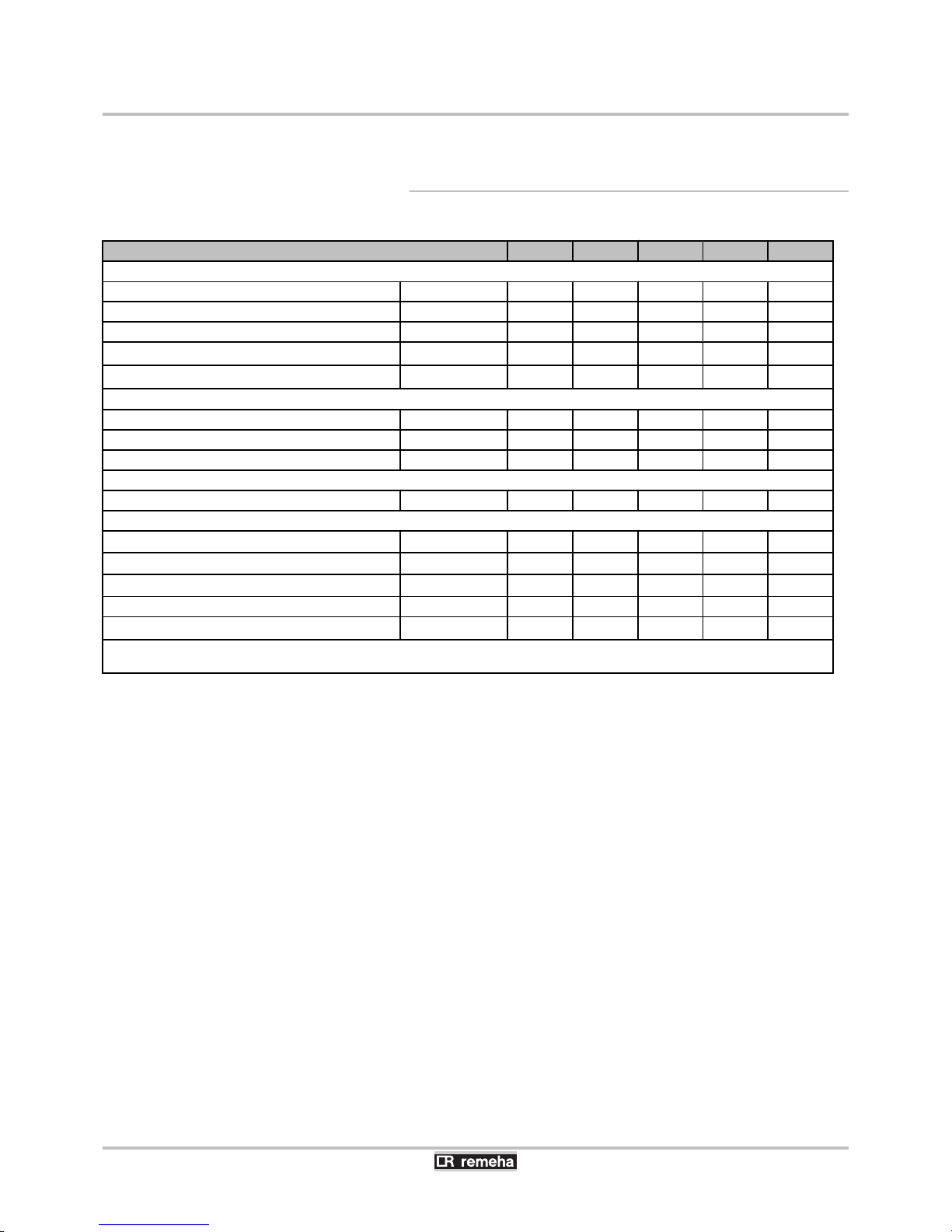
3.2.1. Characteristics of the DHW calorifier
BL 150-2 BL 200-2 BL 300-2 BL 400-2 BL 500-2
Primary circuit (Exchanger)
Maximum operating temperature °C 110 110 110 110 110
Maximum operating pressure Mpa (bar) 1 (10) 1 (10) 1 (10) 1 (10) 1 (10)
Exchanger capacity litres 5.1 6.3 8.1 12.1 14.8
Exchange surface
m
2
0.76 0.93 1.2 1.8 2.2
Pressure drop at 3 m3/h
kPa 11 12 13 17 20
Secondary circuit (domestic water)
Maximum operating temperature °C 95 95 95 95 95
Maximum operating pressure Mpa (bar) 1 (10) 1 (10) 1 (10) 1 (10) 1 (10)
Water content litres 145 195 295 390 495
Weight
DHW calorifiers kg 76 89 111 144 171
Performances related to the type of appliance
Power exchanged
(1)
kW 26 33 39 56 66
Flow per hour (∆T = 35 °C)
(1)
litres per hour 640 810 960 1375 1620
Transfer capacity over 10 minutes (∆T = 30 °C)
(2)
litres per 10 min. 250 340 520 670 780
Maintenance consumption (ΔT=45K) kWh/24h 1.20 1.60 2.00 2.40 2.70
Performance N
L
2.5 4.7 11 15 19
(1) Primary temperature: 80 °C - Domestic cold water inlet: 10 °C - Domestic hot water outlet: 45 °C - Primary flow rate: 3 m3/h
(2) Primary temperature: 80 °C - Domestic cold water inlet: 10 °C - Domestic hot water outlet: 40 °C - Domestic hot water storage: 60 °C
BL 150...500-2 3. Technical description
18/11/2015 - 7607674-001-04
10
Page 12

4 Installation
4.1 Regulations governing installation
CAUTION
Installation of the appliance must be done by a qualified
engineer in accordance with prevailing local and national
regulations.
DANGER
Temperature limit at draw-off points: we would remind you
that the maximum domestic hot water temperature at the
draw-off point is subject to particular regulations in the
various countries where the appliance is sold in order to
protect the consumer. Such regulations must be observed
when installing the appliance
4.2 Package list
4.2.1. Standard delivery
The delivery includes:
4 A DHW calorifier.
4 An installation, use and service manual.
4. Installation BL 150...500-2
11
18/11/2015 - 7607674-001-04
Page 13

4.3 Choice of the location
4.3.1. Type plate
The nameplate affixed to the tank provides important information
regarding the appliance: serial number, model, etc.
CAUTION
The type plate must be accessible at all times.
4.3.2. Positioning of the appliance
CAUTION
Put the appliance in a frost-free location.
4 Place the appliance as close as possible to draw-off points in order
to minimise energy losses through the pipes.
4 Place the appliance on a base frame to facilitate cleaning of the
premises.
4 Install the appliance on a solid, stable structure able to bear its
weight.
4.3.3. Main dimensions
n
Legend
A
Domestic hot water outlet G 1"
Z
Circulation G ¾"
E
Exchanger inlet G 1"
R
Exchanger outlet G1"
T
Domestic cold water inlet + Drain opening G 1"
C003702-B
BL 150...500-2 4. Installation
18/11/2015 - 7607674-001-04
12
Page 14

G : Exterior cylindrical threading, sealed by sheet gasket
BL 150-2 BL 200-2 BL 300-2 BL 400-2 BL 500-2
A
70 70 70 66 71
B
282 282 282 284 283
C
567 657 747 838 896
D
662 840 1142 1157 1213
E
844 1114 1634 1510 1618
F (Ø)
605 605 605 705 755
G
944 1212 1734 1622 1740
n
BL 150-2
G
Ø F
A
B
C
D
E
1
2
3
4
5
C003692-C
n
BL 200-2
C003705-C
G
Ø F
A
B
C
D
E
1
2
3
4
5
4. Installation BL 150...500-2
13
18/11/2015 - 7607674-001-04
Page 15

n
BL 300-2 - BL 400-2 - BL 500-2
C003719-B
G
Ø F
A
B
C
D
E
1
2
3
4
5
4.4 Positioning the appliance
CAUTION
4 Have 2 people available.
4 Handle the appliance with gloves.
1. Remove the packaging from the DHW calorifier, leaving the
calorifier on the pallet used for transport.
2. Remove the protective packaging.
3. Remove the 3 screws securing the calorifier to the pallet.
4. Lift the DHW calorifier and place it in its final position, respecting
the distances shown on the diagram.
200
200
350
L000565-B
BL 150...500-2 4. Installation
18/11/2015 - 7607674-001-04
14
Page 16

4.5 Levelling
The DHW calorifier is levelled using the 3 feet (delivered in the
instructions pack) to be screwed to the bottom of the DHW calorifier.
1. Screw the 3 adjustable feet onto the bottom of the tank.
2. Level the appliance using the adjustable feet.
4 Adjustment range: 10 mm.
4 Use metal blocks under the feet of the calorifier if
necessary.
CAUTION
Do not place the blocks on the exterior sides of the
domestic hot water calorifier.
4.6 Fitting the DHW sensor
C003702-C
1
3
2
1. Insert the sensor into the sensor tube with the help of the sensor
tube separator.
The sensor tube separator is provided in the instructions
bag.
2. Check that the sensors are correctly positioned in the sensor
tube.
3. Check the mounting of the sensor tube separator.
4.7 Hydraulic installation diagram
4.7.1. Legend
A
Boiler, Heat pump
B
Regulation
L000382-A
1
2
4. Installation BL 150...500-2
15
18/11/2015 - 7607674-001-04
Page 17

1
Heating flow
2
Heating return
3
3-bar safety valve
4
Pressure gauge
7
Automatic air vent
9
Isolating valve
10
3-way mixing valve
11
Heating pump
16
Expansion vessel
17
Drain cock
18
Filling the heating circuit
21
Exterior temperature sensor
23
Mixing valve outlet temperature sensor
24
DHW calorifier exchanger primary inlet
25
DHW calorifier heat exchanger primary outlet
26
DHW load pump
27
Non-return valve
28
Domestic cold water inlet
29
Pressure reducer
30
Safety unit
32
D.H.W. loop back pump
33
DHW temperature sensor
44
Thermostat limiting the temperature to 65°C with manual
reset for underfloor heating
46
3-way directional valve with reversal motor
50
Disconnector
52
Differential valve
54
End of the discharge pipe free and visible 2 to 4 cm above
the flow funnel
56
Circulation
57
Domestic hot water outlet
64
direct heating circuit (example: radiators)
65
Heating circuit which may be at low temperature (heated
floor or radiators)
67
Manual head valve
68
Condensates neutralisation system
BL 150...500-2 4. Installation
18/11/2015 - 7607674-001-04
16
Page 18

4.7.2. Example of a wall-mounted condensing gas
boiler
4.7.3. Example with a floor standing boiler
68
9
9
27
27
32
33
25
56
L000369-B
24
30
50
50Hz
230V
46
16
64
67
B
A
11
21
27
9
1
4
2
3
50
189
9
9
9
9
27
27
32
16
33
25
26
56
57
21
50Hz
230V
7
2
3
4
1
7
17
65
9
9
52
11
10
27
°C °C
23
44
L000368-B
4
24
30
9
A
4. Installation BL 150...500-2
17
18/11/2015 - 7607674-001-04
Page 19

4.7.4. Safety unit
9
Isolating valve
28
Domestic cold water inlet
29
Pressure reducer
30
Safety unit
54
End of the discharge pipe free and visible 2 to 4 cm above
the flow funnel
a
Cold water inlet with an integrated non-return valve
b
Connection to the DHW calorifer cold water inlet
c
Stop cock
d
0.7 MPa safety valve (7 bar)
e
Drain opening
4.8 Hydraulic connections
4.8.1. Hydraulic connection of the primary circuit
(exchanger circuit)
¼See diagram : "Hydraulic installation diagram", page 15.
For the hydraulic connection of 150 l to 300 l tanks and the boiler (right
or left), we offer optional hydraulic connection kits.
For connection using these kits, refer to the instructions delivered with
them.
4.8.2. Connecting the calorifer to the domestic
water circuit (secondary circuit)
When making the connections, it is imperative that the standards and
corresponding local directives are respected. To reduce heat losses
as much as possible, insulate the pipes.
n
Specific precautions
Before making the connection, rinse the drinking water inlet
pipes in order not to introduce metal or other particles into the
appliance’s tank.
L000370-B
d
(54)
2 cm
99 29
17
27
30
28
BL 150...500-2
4. Installation
18/11/2015 - 7607674-001-04
18
Page 20

n
Safety valve
CAUTION
In accordance with safety rules, a safety valve calibrated
to 7 bar (0.7 MPa) is mounted on the tank’s domestic cold
water inlet.
4 Integrate the safety valve in the cold water circuit.
4
Install the safety valve close to the calorifer in a place which is
easy to access.
n
Size
4 The diameter of the safety unit and its connection to the calorifer
must be at least equal to the diameter of the domestic cold water
inlet on the calorifer.
4 There must be no cut-off element between the valve or the safety
unit and the domestic hot water calorifer.
4 The outlet pipe in the valve or safety assembly must not be
blocked.
To avoid restricting the flow of water in the event of overpressure:
4 The discharge pipe from the safety unit must have a continuous
and sufficient gradient.
4 The cross section of the discharge pipe from the safety unit must
be at least equal to the cross section of the opening of the safety
unit outlet.
n
Isolating valves
Hydraulically isolate the primary and secondary circuits using stop
valves to facilitate maintenance operations on the unit. The valves
make it possible to carry out maintenance on the calorifer and its
components without draining the entire installation.
These valves are also used to isolate the calorifer unit when
conducting a pressurised check on the leak tightness of the
installation if the test pressure is greater than the admissible operating
pressure.
CAUTION
If the mains pipes are made of copper, fit a sleeve made
of steel, cast iron or any other insulating material between
the tank’s hot water outlet and the pipes to prevent
corrosion to the connection.
4. Installation BL 150...500-2
19
18/11/2015 - 7607674-001-04
Page 21

n
Connecting the domestic cold water
Make the connection to the cold water supply according to the
hydraulic installation diagram.
The components used for the connection to the cold water supply
must comply with the prevailing standards and regulations in the
country concerned.
4 Install a water drain in the boiler room and a funnel-siphon for the
safety unit.
4 Fit a one-way valve to the domestic cold water circuit.
n
Pressure reducer
If the mains pressure exceeds 80% of the calibration of the valve or
safety unit (e.g. 8 bar (0,8 MPa) for a safety unit calibrated to 10 bar
(1,0 MPa)), a pressure reducer must be installed upstream of the
appliance. Install the pressure reducer downstream the water meter
in such a way as to ensure the same pressure in all of the installation
pipes.
n
Domestic hot water circulation loop
To guarantee the availability of hot water as soon as the taps are
turned on, a circulation loop between the draw-off points and the
recirculation pipes in the DHW calorifer can be installed. A non-return
valve must be included in this loop.
Run the domestic hot water circulation loop via the boiler
control system or an additional timer program to optimse
energy consumption.
n
Measures to take to prevent hot water flow return
Fit a one-way valve to the domestic cold water circuit.
BL 150...500-2 4. Installation
18/11/2015 - 7607674-001-04
20
Page 22

5 Commissioning
5.1 Protection against legionnella
(Only for the 500 L model)
WARNING
It is compusory that DHW calorifers with a capacity of more
than 400 litres abide by the Order on "Protection against
legionella" (Other countries: Abide by prevailing
regulations)
Apply one of these 2 instructions:
4 The domestic hot water must at be at a temperature of more than
or equal to 55°C at the appliance outlet at all times.
4 The domestic hot water must be brought up to a minimum
temperature for a minimum duration at least once every 24
hours. See table below:
Minimum temperature maintenance time
(minutes)
Water temperature (°C)
2 more than or equal to 70
4 65
60 60
5.2 Putting the appliance into operation
CAUTION
Initial commissioning must be done by a qualified
professional.
1. Flush the domestic circuit and fill the calorifer through the cold
water inlet tube.
2. Open a hot water tap.
3. Completely fill the domestic hot water calorifer via the cold water
inlet pipe, leaving the hot water valve open.
4. Close the hot water valve when the water flow is regular, without
noise in the pipes.
5. Degas all DHW pipes by repeating steps 2 to 4 for each hot water
tap.
Carefully degas the DHW tank and the distribution network
in order to eliminate noises and hammering caused by
trapped air moving in the pipes during draw-off.
6. Vent the tank exchanger circuit using the bleed valve provided for
this purpose.
5. Commissioning
BL 150...500-2
21
18/11/2015 - 7607674-001-04
Page 23

7. Check the safety devices (particularly the valve or safety unit),
referring to the instructions provided with these components.
CAUTION
During the heating process, a certain amount of water may
flow through the valve or safety unit, this is caused by
water expansion. This phenomenon is completely normal
and must in no event be hindered.
5.3 Drinking water quality
In regions where the water is very hard (TH > 20 °f), we recommend
fitting a softener.
The hardness of the water must always be between 12 °f and 20 °f to
be capable of providing effective protection against corrosion.
The softener does not bring about derogation of our warranty,
provided that the softener is:
- approved and set in accordance with the codes of practice and the
recommendations given in the instruction manual for the softener
- regularly inspected
- regularly serviced
BL 150...500-2 5. Commissioning
18/11/2015 - 7607674-001-04
22
Page 24

6 Checking and maintenance
6.1 General instructions
CAUTION
4 Maintenance operations must be done by a qualified
engineer.
4 Only original spare parts must be used.
6.2 Checking the safety valve or unit
Operate the safety valve or unit at least 1 time per month to check
that it is running correctly. This check provides forewarning of any
occurrences of excess pressure that may damage the domestic hot
water calorifier.
WARNING
Failure to comply with this maintenance rule may cause
deterioration of the DHW tank and the cancellation of the
guarantee.
6.3 Cleaning the casing material
Clean the outside of appliances using a damp cloth and a mild
detergent.
6.4 Checking the magnesium anode
Check the condition of the anode at the end of the first year. After the
first check, determine the frequency of future checks on the basis of
anode wear. The magnesium anode must be checked at least every
2 years.
1. Remove the inspection hatches.
¼
See chapter: "Removing the inspection hatches", page
24.
2. Descale the calorifier if necessary.
¼
See chapter: "Descaling", page 24.
3. Measure the diameter of the anode.
Replace the anode if its diameter is less than 15 mm.
4. Reassemble the anode/inspection hatch unit.
¼
See chapter: "Remounting the inspection hatches", page
25.
Ø > 15 mm =
Ø < 15 mm =
C003699-B
6. Checking and maintenance
BL 150...500-2
23
18/11/2015 - 7607674-001-04
Page 25

6.5 Descaling
In regions with hard water, annual descaling of the appliance is
recommended in order to maintain its performance.
1. Remove the inspection hatches.
¼
See chapter: "Removing the inspection hatches", page
24.
2. Check the magnesium anode each time the hatch is opened.
¼
See chapter: "Checking the magnesium anode", page 23.
3. Remove limescale deposits in the form of sludge or strips in the
bottom of the tank. On the other hand, do not touch limescale
adhering to the walls of the tank as it provides effective protection
against corrosion and improves the insulation of the DHW
calorifier.
4. Remove limescale deposits from the exchanger to guarantee its
performance.
5. Fit the unit together.
¼
See chapter: "Remounting the inspection hatches", page
25.
6.6 Removing and remounting the inspection hatches
CAUTION
To guarantee tightness, the gasket unit must be replaced
each time the hatch is opened.
4 Use a new lip gasket and retainer ring for the top
inspection hatch.
4 Have a new gasket on hand for the side inspection
hatch.
6.6.1. Removing the inspection hatches
1. Turn off the domestic cold water inlet.
2. Drain the calorifier.
The domestic cold water inlet is also the drain opening.
3. Remove the inspection hatches.
BL 150...500-2
6. Checking and maintenance
18/11/2015 - 7607674-001-04
24
Page 26

6.6.2. Remounting the inspection hatches
1. Replace the lip seal and position it in the visit opening, making sure
that you place its lug outside the DHW tank.
2. Replace the sheet gasket.
A
Side trap without anode
B
Side trap with anode
3. Fit the unit together.
CAUTION
Use a torque wrench.
Magnesium anode: Torque load 8 N·m.
The flange mounting bolts must not be excessively tight.
Flange
Torque load
Lip gasket 6 N·m +1/-0
Sheet gasket 15 N·m
Approximately 6 N·m is obtained by manipulating the box
spanner with the small lever and 15 N·m by manipulating
it with the large lever.
4. After reassembly, check the watertightness of the lateral flange.
5. Switch on.
¼
See chapter: "Putting the appliance into operation", page
21.
L000555-A
1
6x
A
2
L000556-A
B
2
L000557-A
6. Checking and maintenance
BL 150...500-2
25
18/11/2015 - 7607674-001-04
Page 27

6.7 Maintenance form
No.
_____
Date
_________
Checks made
______________________________
Remarks
_____________________By_______________
Signature
____________
BL 150...500-2 6. Checking and maintenance
18/11/2015 - 7607674-001-04
26
Page 28

7 Spare parts
7.1 General
When it is observed subsequent to inspection or maintenance work
that a component in the appliance needs to be replaced, use only
original spare parts or recommended spare parts and equipment.
Send the component to be replaced to your supplier’s Returned
Goods Department if the component in queston is under warranty
(see general terms and conditions of sale and delivery).
Always ensure that your return package is accompanied
by the completed return form, see attached example. In this
way, your supplier can fulfil his warranty obligations more
easily and more effectively.
Customer
Reference
Date
Name
Address
Town/Postcode
Telephone
Contact person
Order number
Code no. Description
Serial number
(1)
Type Installation date Reason for the exchange Reference
(1) This information can be found on the rating plate.
7.2 Spare parts
7. Spare parts
BL 150...500-2
27
18/11/2015 - 7607674-001-04
Page 29

7.2.1. Domestic hot water tanks
L000578-A
1
11
4
7
3
15
6
5
16
14
4
5
6
13
4
5
6
12
10
11
4
6
5
2
8
9
Markers Reference Description BL 150-2 BL 200-2 BL 300-2 BL 400-2 BL 500-2
1
97860646 Adjustable foot M10 x 35 x x x x x
2
95365613 Contact spring for pocket x x x x x
3
200021501 Inspection trap screws x x x x x
4
95014035 Seal ø 35 x 8.5 x 2 x x x x x
5
94974527 Nylon brace x x x x x
6
89604901 Anode earthing wire x x x x x
7
300026994 Insulation, buffer tank x x x x x
8
300026735 Side cover x x x x x
BL 150...500-2 7. Spare parts
18/11/2015 - 7607674-001-04
28
Page 30

Markers Reference Description BL 150-2 BL 200-2 BL 300-2 BL 400-2 BL 500-2
9
300026876 Demi plastron cover x x x x x
10
89705511 7 mm gasket + 5 mm retainer ring x x x x x
11
300026031 Gasket ring EPDM x x x x x
12
200022466
Complete top inspection trap with anode and
gasket
x
x x
12
200007273
Complete top inspection trap with anode and
gasket
x
12
89555501
Complete top inspection trap with anode and
gasket
x
13
89588912
Complete anode diameter 33 mm - length
290 mm (1x) - For top trap
x
13
89608950
Complete anode diameter 33 mm - length
420 mm (1x) - For top trap
x x x
13
89628562
Complete anode diameter 33 mm - length
450 mm (1x) - For top trap
x
14
200021970 Complete lateral cover with gaskets and screws x
15
200022440
Complete side trap with anode, gaskets and
screws
x x
15
200022441
Complete side trap with anode, gaskets and
screws
x
16
89588912
Complete anode diameter 33 mm - length
290 mm (1x) - For side trap
x x
16
89608950
Complete anode diameter 33 mm - length
420 mm (1x) - For side trap
x
7. Spare parts BL 150...500-2
29
18/11/2015 - 7607674-001-04
Page 31

8 Warranty
8.1 General
You have just purchased one of our appliances and we thank you for
the trust you have placed in our products.
Please note that your appliance will provide good service for a longer
period of time if it is regularly checked and maintained.
Your installer and our customer support network are at your disposal
at all times.
8.2 Warranty terms
The following provisions are not exclusive of the buyer being able
benefit from the legal provisions applicable regarding hidden defects
in the buyer’s country.
Starting from the purchase date shown on the original installer’s
invoice, your appliance has a contractual guarantee against any
manufacturing defect.
The length of the guarantee is mentioned in the price catalogue.
The manufacturer is not liable for any improper use of the appliance
or failure to maintain or install the unit correctly (the user shall take
care to ensure that the system is installed by a qualified engineer).
In particular, the manufacturer shall not be held responsible for any
damage, loss or injury caused by installations which do not comply
with the following:
4 applicable local laws and regulations,
4 specific requirements relating to the installation, such as national
and/or local regulations,
4 the manufacturer’s instructions, in particular those relating to the
regular maintenance of the unit,
4 the rules of the profession.
The warranty is limited to the exchange or repair of such parts as have
been recognised to be faulty by our technical department and does
not cover labour, travel and carriage costs.
The warranty shall not apply to the replacement or repair of parts
damaged by normal wear and tear, negligence, repairs by unqualified
parties, faulty or insufficient monitoring and maintenance, faulty
power supply or the use of unsuitable fuel.
Sub-assemblies such as motors, pumps, electric valves etc. are
guaranteed only if they have never been dismantled.
The legislation laid down by european directive 99/44/EEC,
transposed by legislative decree No. 24 of 2 February 2002 published
in O.J. No. 57 of 8 March 2002, continues to apply.
BL 150...500-2
8. Warranty
18/11/2015 - 7607674-001-04
30
Page 32

en
Appendix
Information on the ecodesign and energy labelling directives
Page 33

Contents
1 Specific information . . . . . . . . . . . . . . . . . . . . . . . . . . . . . . . . . . . . . . . . . . . . . . . . . . . . . . . . . . . . . . . . . . . . . . . . . . . . . . . . . .3
1.1 Recommendations . . . . . . . . . . . . . . . . . . . . . . . . . . . . . . . . . . . . . . . . . . . . . . . . . . . . . . . . . . . . . . . . . . . . . . . . . . . . . 3
1.2 Ecodesign Directive . . . . . . . . . . . . . . . . . . . . . . . . . . . . . . . . . . . . . . . . . . . . . . . . . . . . . . . . . . . . . . . . . . . . . . . . . . . . 3
1.3 Technical data - Hot water storage tank . . . . . . . . . . . . . . . . . . . . . . . . . . . . . . . . . . . . . . . . . . . . . . . . . . . . . . . . . . . . . 3
1.4 Disposal and Recycling . . . . . . . . . . . . . . . . . . . . . . . . . . . . . . . . . . . . . . . . . . . . . . . . . . . . . . . . . . . . . . . . . . . . . . . . . .3
1.5 Product fiche - Hot water storage tanks . . . . . . . . . . . . . . . . . . . . . . . . . . . . . . . . . . . . . . . . . . . . . . . . . . . . . . . . . . . . . 3
Contents
2 7607674 - ErP02 - 18112015
Page 34

1 Specific information
1.1 Recommendations
Note
Only qualified persons are authorised to assemble, install and
maintain the installation.
1.2
Ecodesign Directive
This product conforms to the requirements of European Directive
2009/125/EC on the ecodesign of energy-related products.
1.3
Technical data - Hot water storage tank
Tab.1 Technical parameters for hot water storage tank
Product name BL 150–2 BL 200–2 BL 300–2 BL 400–2 BL 500–2
Storage volume V l 145 195 295 390 495
Standing loss S W 50 67 83 100 113
1.4 Disposal and Recycling
Note
Removal and disposal of the domestic hot water tank must be car
ried out by a qualified installer in accordance with local and nation
al regulations.
1. Cut the electricity to the domestic hot water tank.
2. Disconnect the cables on the electrical components.
3. Close the domestic water inlet valve.
4. Drain the installation.
5. Dismantle all water connections fitted to the domestic hot water tank
outlet.
6. Scrap and recycle the domestic hot water tank in accordance with
local and national regulations.
1.5 Product fiche - Hot water storage tanks
Tab.2 Product fiche for hot water storage tanks
Brand name - Product name BL 150–2 BL 200–2 BL 300–2 BL 400–2 BL 500–2
Energy efficiency class
BCCCC
Standing loss W 50 67 83 100 113
Storage volume l 145 195 295 390 495
1 Specific information
7607674 - ErP02 - 18112015 3
Page 35

Page 36

© Copyright
All technical and technological information contained in these technical instructions,
as well as any drawings and technical descriptions supplied, remain our property
and shall not be multiplied without our prior consent in writing.
18/11/2015
7607674- 001- 04
 Loading...