

REMEHA Avanta Range 24c, Avanta Range 28c, Avanta Range 24s, Avanta Range 35c, Avanta Range 30s Installation & Service Manual
...
Installation &
Service Manual
Remeha Avanta Range
24c | 28c | 35c | 39c | 18s | 24s | 30s

Remeha Avanta Plus
Benchmark places responsibilities on both manufacturers and installers. The purpose is to ensure that
customers are provided with the correct equipment for their needs, that it is installed, commissioned and
serviced in accordance with the manufacturer’s instructions by competent persons and that it meets the
requirements of the appropriate Building Regulations. The Benchmark Checklist can be used to demonstrate
compliance with Building Regulations and should be provided to the customer for future reference. Installers
are required to carry out installation, commissioning and servicing work in accordance with the Benchmark
Code of Practice which is available from the Heating and Hotwater Industry Council who manage and promote the Scheme.
Visit www.centralheating.co.uk for more information.
CONTENTS
INTRODUCTION 4
1 SAFETY 5
1.1 General safety 5
1.2 Safety during assembly and installation 5
1.3 Safety during installation, inspection and maintenance 5
2 INSTALLATION 7
2.1 Scope of delivery 7
2.2 Mounting the boiler 7
2.2.1 Clearance requirements 7
2.2.2 Dimensions and connection points. 8
2.2.3 Mounting the Remeha Avanta Plus 10
2.3 Water-side connections 10
2.3.1 Water fl ow 10
2.3.2 Circulation pumps 11
2.3.3 Additional guidelines for the domestic and CH water 11
2.3.4 Water treatment 11
2.3.5 Safety valve discharge 12
2.3.6 Expansion vessel 13
2.3.7 Connecting DHW pipes 13
2.3.8 Connecting the ‘CH return’ 14
2.3.9 Connecting ‘CH fl ow’ 14
2.3.10 Connecting condensate drain 15
2.3.11 Connecting under fl oor heating 15
2.4 Gas-side connections 15
2.4.1 Additional guidelines for gas connections 15
2.4.2 Adjusting boiler to other gas-type 16
2.4.3 Connecting the gas supply 16
2.5 Flue terminal and air supply connections 16
2.5.1 Flue terminal positions 16
2.5.2 Room sealed fl ue 17
2.5.3 Connecting the fl ue terminal and air supply 18
2.6 Electrical connection 19
2.6.1 The control unit 19
2.7 Connecting external controls 20
2.7.1 On/off control – room temperature (volt free switching) 22
2.7.2 Time control using an internal or external 230 V clock 22
2.7.3 Connecting a 230 V time clock in combination with a modulating room control 23
2.7.4 Modulating control – room or outside compensation 23
2.7.5 Connecting an outside temperature sensor 24
2.7.6 Connecting the DHW sensor/thermostat 25
2.7.7 Connecting a frost thermostat 25
2.7.8 Connecting an external interlock 26
2.7.9 Connecting remote alarm, boiler run indication and external pump relay 26
2.7.10 Connecting a PC/PDA 26
2

2.9 Commissioning 28
2.9.1 Control Panel 28
2.9.2 Additional guidelines for commissioning 28
2.9.3 Putting the boiler into operation 28
2.9.4 Normal start-up procedure 34
2.9.5 Error during the start-up procedure 35
2.9.6 Read out settings 36
2.9.7 Adjust the boiler according to the system 36
2.9.8 Changing the parameters at service level (with access code) 37
2.9.9 Changing the maximum output (Hi) for CH operation 40
2.9.10 Restore factory settings 42
2.10 Putting the boiler out of operation 42
2.10.1 Boiler with frost protection, during longer periods of non-use 42
2.10.2 Boiler without frost protection, during longer periods of non-use 42
3 INSPECTION AND MAINTENANCE 43
3.1 Inspection 43
3.1.1 Checking the water pressure 44
3.1.2 Checking the fl ue pipes and air supply pipes for leaks 44
3.1.3 Checking the condensate siphon 45
3.1.4 Checking the ignition electrode 45
3.2 Maintenance 47
4 ERRORS 52
4.1 General 52
4.2 Error codes 52
4.3 Control stop or lock-out 54
4.4 Error memory 55
4.4.1 Error read outs 55
4.4.2 Deleting errors 55
5 SERVICE PARTS 56
5.1 General 56
6 EC declaration 59
7 REGULATIONS 60
7.1 EC regulations 60
7.2 Remeha factory test 60
7.3 Additional guidelines 60
8 TECHNICAL SPECIFICATIONS and working principle 61
8.1 Technical data 61
8.2 The boiler components 63
8.3 Working principle 63
8.3.1 Regulating 64
8.3.2 Advanced boiler control (‘abc®’-control) 64
8.3.3 Regulating the water temperature 64
8.3.4 Low fl ow / water protection 65
8.3.5 High Limit temperature protection 65
9 efficiency data and gas efficiency labels 66
9.1 Annual efficiency 66
9.2 Water-side efficiency 66
3

INTRODUCTION
Remeha Avanta Plus
The Remeha Avanta Plus is a series of high-efficiency fully
condensing central heating boilers, for wall mounting, available
in the following types:
• Remeha Avanta Plus 24c, 28c, 35c and 39c - with inte-
grated domestic hot water system (Combi-type)
• Remeha Avanta Plus 18s, 24s, 30s
- without integrated domestic hot water system
(System-type)
These technical instructions contain useful and important information for the correct installation, operation and maintenance
of the Remeha Avanta Plus combi and system boilers.
Read these instructions carefully before putting the boiler into
operation, familiarise yourself with their control functions and
operation, strictly observing the instructions given. Failure to
do so may invalidate warranty or prevent the boiler from
operating correctly.
fi g. 01 Remeha Avanta Plus
112952.LT.GB.W7H.001
The installation, commissioning, inspection and servicing of
the boiler must be carried out by a competent registered engineer who holds valid ACS certification and in accordance with
current gas safety (installation and use) regulations, the building regulations and all other relevant codes of practice.
All electrical work must be carried out by a competent engineer and to be installed in accordance with the current IEE
regulations.
On commissioning the certificate in the Benchmark Checklist
within the Installation + Service manual must be completed
and left on site with a copy send on to Broag Ltd for
registration purposes.
If you have any questions, require an engineer to call on site,
or if you need more information about specific subjects relating
to this boiler, or it's installation please do not hesitate to contact our technical help line 0118 978 3434.
When contacting Broag with a problem on the boiler, please
have available the boiler type, Serial No (located on the
bottom of the casing), and the symptoms or fault code (the
fault code is a series of flashing red digits in the display panel).
The data published in these technical instructions is based on
the latest information (at date of publication) and may be subject to revisions.
We reserve the right to continuous development in both design
and manufacture, therefore any changes to the materials or
technology employed may not be retrospective nor may we be
obliged to adjust earlier supplies accordingly.
4

1 SAFETY
1.1 General safety
The following pictograms are used in this Installation and Service manual to specifically draw certain points to your attention:
Tip Useful tip or practical advice.
Indication Important instruction in carrying out a
particular operation.
Warning Possible danger of personal injury
or material damage to the regulator,
building or environment.
Danger Serious personal injury can occur
because of risk of electric shocks.
1.2 Safety during assembly and installation
Observe the appropriate safety measures, as given in these
instructions.
Can you smell gas? What to do:
• do not smoke and do not create any flame or sparks;
• do not use any electric switches;
• turn off the gas tap;
• open windows and doors;
• trace possible leaks and seal them.
Warning! If the leak is before the gas meter, alert your gas
supplier, TRANSCO, tel. 0800 111 999
Can you smell smoke or flue gasses? What to do:
• isolate power supply.
• open windows and doors;
• trace possible leaks and seal them.
1.3 Safety during installation, inspection and
maintenance
Under the current Gas Safety (Installation & Use) Regulations,
the Remeha Avanta Plus, in common with all gas appliances,
must be installed by a competent person in accordance with
that regulation.
Statutory regulations in any country, cannot be overridden by
any of the notes or instructions from the manufacturer.
Compliance with National Standards does not provide any
degree of immunity from legal obligations. In the UK, the
installation must be in accordance with the national and local
norms and requirements.
For any issues or circumstances not addressed within these
instructions, please call our After Sales Department
0118 9743070
5
fi g. 02 WRAS logo
LT.AL.W7H.000.074
Remeha Avanta Plus
The Remeha Avanta Plus (combi and system) is a WRAS
(Water regulations) approved product.
Remeha Avanta Plus (combi and system) - PIN:
0063BQ3009
Gas Council numbers:
Remeha Avanta Plus 28c: 47-673-02
Remeha Avanta Plus 35c: 47-673-03
Remeha Avanta Plus 39c: 47-673-04
Remeha Avanta Plus 18s: 41-288-11
Remeha Avanta Plus 24s: 41-288-05
Remeha Avanta Plus 30s: 41-288-12
Classification type for evacuation of the combustion products;
according EN 483: see Par. 8.1.
Health and safety information
• The weight of the Avanta Plus system and combi boilers
exceed the maximum lift weight for one person. Please
ensure all necessary care is taken when lifting the boiler on
to the wall mounting plate.
• All sealants and gaskets are free from harmful products. On
first firing the boiler, a smell from the sealants and gaskets
may be present and should cease after a short period.
Remeha Avanta Plus 24c: 41-288-01
6
2 INSTALLATION
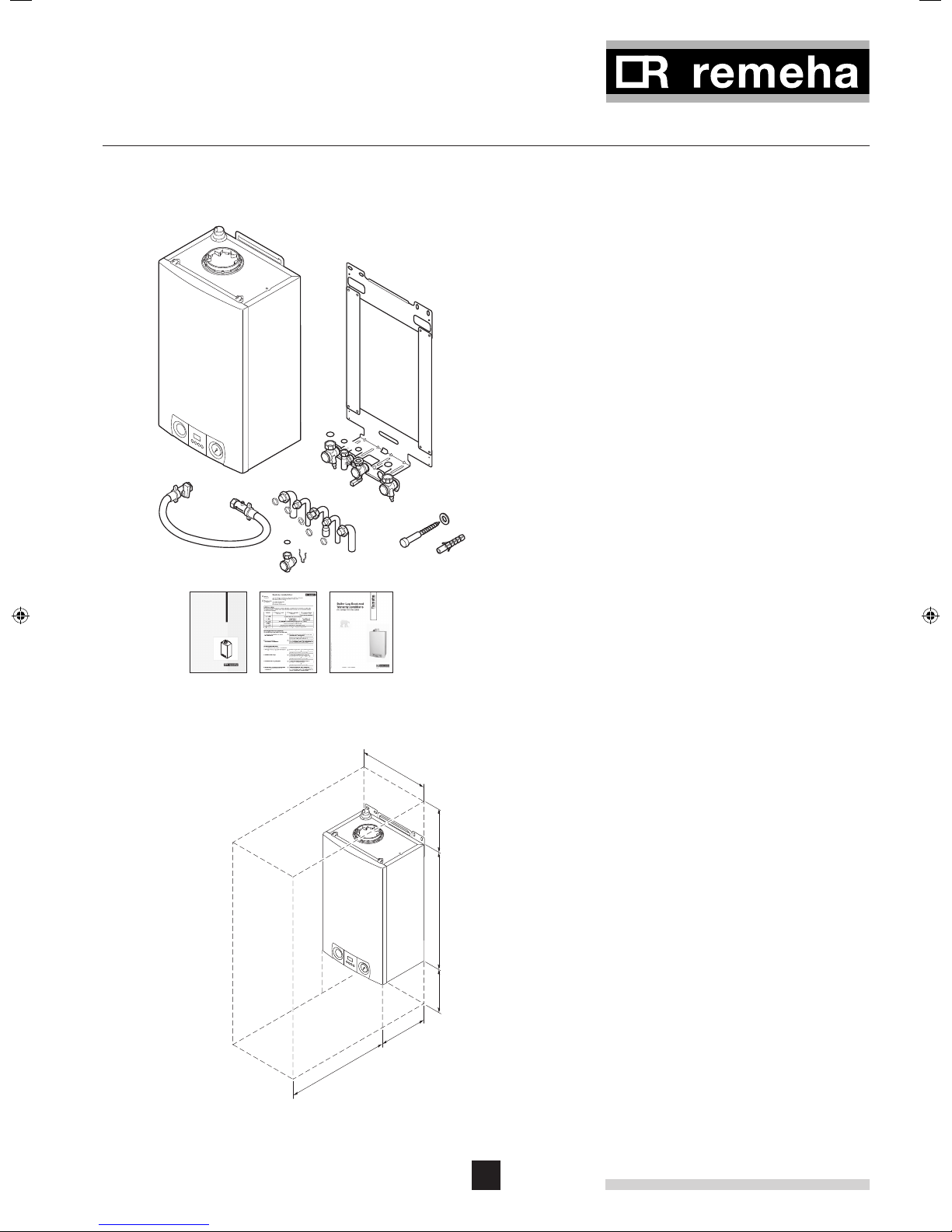
2.1 Scope of delivery
The standard delivery of the Remeha Avanta Plus boiler
includes:
- the boiler (including pressure gauge and safety valve);
- mounting plate (including isolation valve set and washers);
- nylon plugs and screws for fixing mounting plate;
- copper tails 15/22 mm;
- mounting template;
- filling loop;
- Warranty Leaflet (The terms and conditions of the warranty
are included in the warranty leaflet, on installation of the
boiler please fill in the registration card and return to BroagRemeha);
- Installation and Service manual and Users guide.
This Installation and Service manual deals with the standard
supplied boiler only. For the installation or assembly of any
3x
3x
optional accessories supplied with the boiler, such as stand off
frame, pipework kits, cover plate, control kits, etc, please refer
3x
to the Assembly Instructions supplied with these accessories.
Instructieservice
AvantaPlus
fi g. 03 Scope of delivery
112952.LT.GB.W7H.011
400
2.2 Mounting the boiler
Packed in the box with the Remeha Avanta Plus box is
this Installation and Service manual. Read instructions and
remarks carefully. This section includes the guidelines and
instructions for the connection of gas, water, electricity, safety
devices, the regulator, control unit, flue discharge and air supply.
2.2.1 Clearance requirements
The gas and water connections are located on the bottom of
the boiler whilst the air in and flue gas outlet is located on the
top of the boiler. The boiler is supplied as standard with pipework tails to allow connections facing downwards.
min
Optional stand off frame and pipework kits are available
to enable the pipework to run upwards behind the boiler if
.
250
required. For installation, servicing and inspection min. 600
mm in front of the boiler is required. If this free space is
obtained by opening a door or removing a panel, the boiler
6
7
0
may be installed for instance in a closed cupboard.
For ease of installation we recommend clearances of 0.5 cm
at the side so that the unit is easy to open, with a free space
of 25 cm under the appliance and 25 cm above the appliance,
as the minimum requirement.
min
00
3
However once installed, it is possible to reduce these clear-
.25
0
ances to 22 cm at the top, and 5 cm at the bottom provided
the boiler front panel can be removed and the isolating valves
are easily accessible without the use of tools”
fi g. 04 Clearance requirements
112952.LT.GB.W7H.003
min.600
7
Remeha Avanta Plus
670
300
74.5
132.5
21
73.3(2x)
71.5
160
328.5
400
379
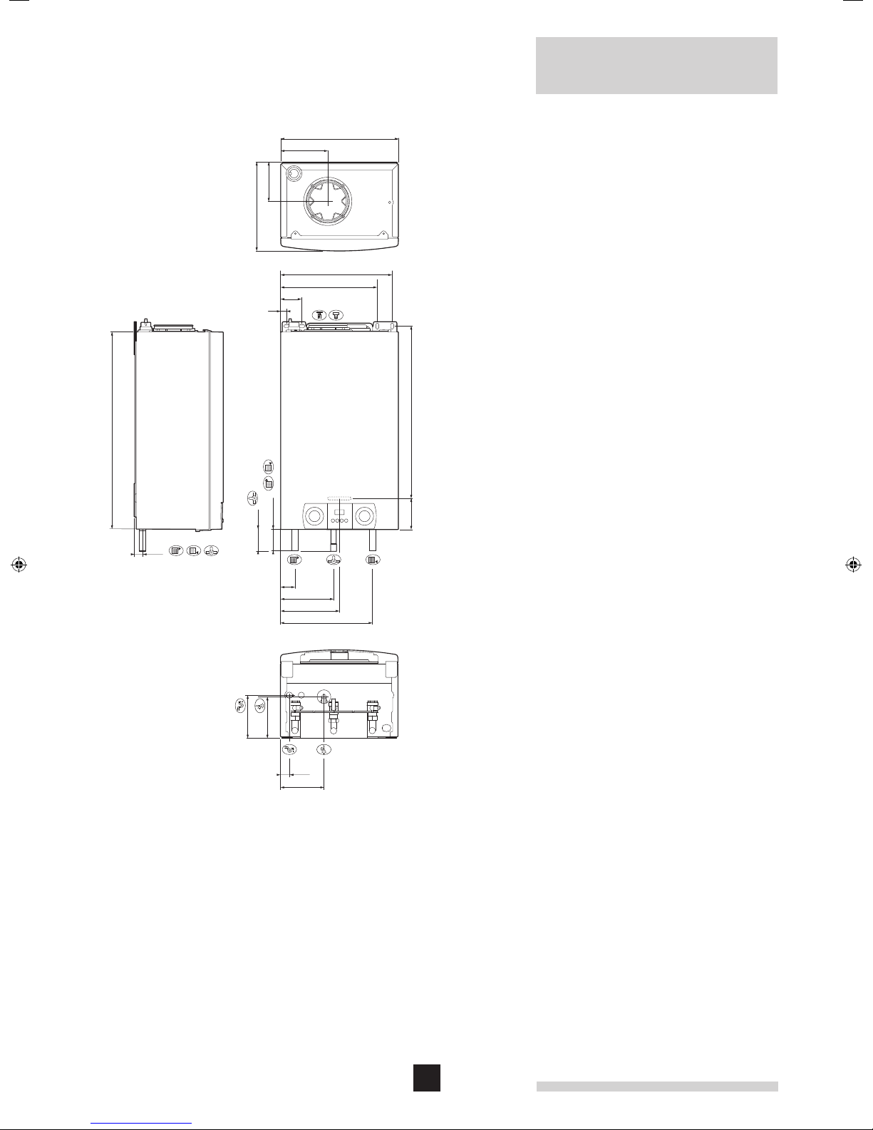
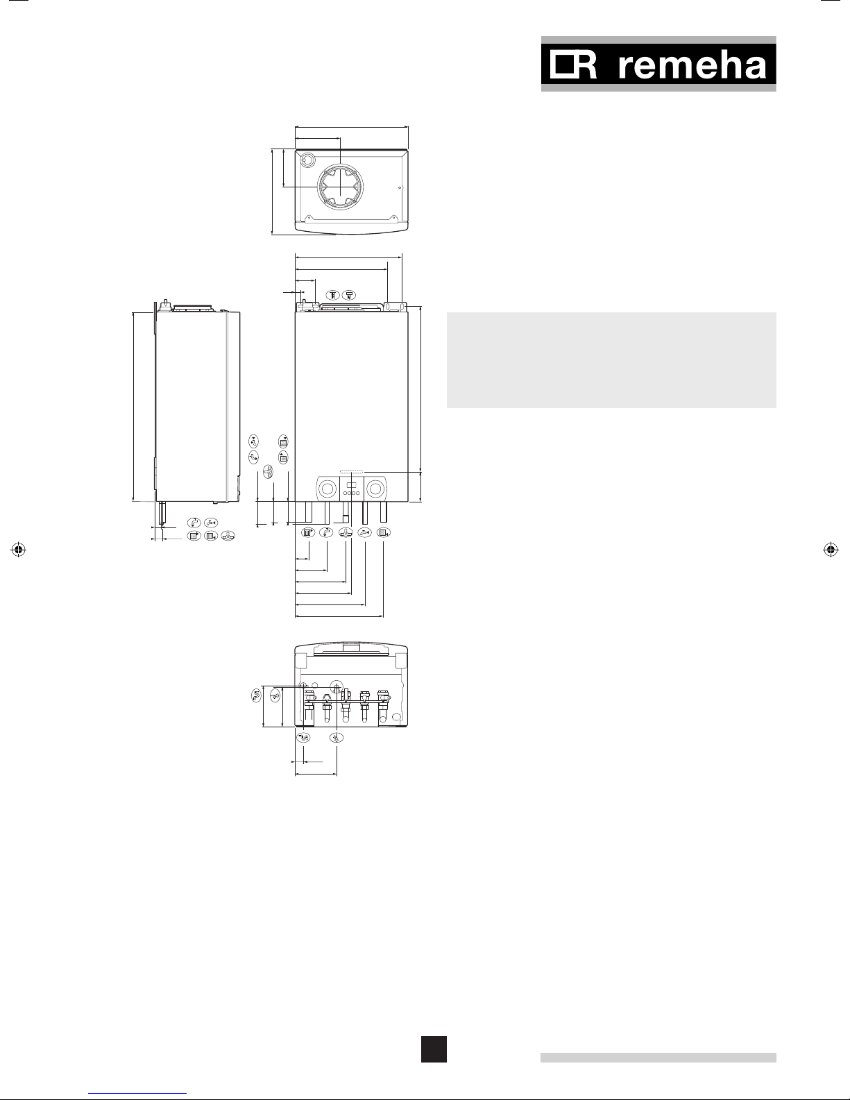
2.2.2 Dimensions and connection points.
System type
Return connection Ø 22 mm
Flow connection Ø 22 mm
Gas connection Ø 22 mm
Combustion air inlet Ø 100 mm (concentric)
Flue duct Ø 60 mm (concentric)
Condensate drain connection ¾”
(standard overflow pipe size)
Connection safety valve Ø 15 mm
584106
26.5
49
180.75
200
312.5
146.7
141.7
24
systeem
30.5
148
fi g. 05 Dimensions and connection points of the Remeha Avanta
Plus system
112952.LT.GB.W7H.005
8
400
670
300
74.5
79.8(2x)
132.5
71.5
21
73.3(2x)
160
328.5
379
Combi type
Return connection Ø 22 mm
Flow connection Ø 22 mm
Gas connection Ø 22 mm
Combustion air inlet Ø 100 mm (concentric)
Flue duct Ø 60 mm (concentric)
DHW inlet (cold) connection Ø 15 mm
DHW outlet (hot) connection Ø 15 mm
Condensate drain connection ¾” (standard overflow pipe
size)
Connection safety valve Ø 15 mm
• Based on the guidelines and the required installation
space, determine where to mount the Remeha Avanta
Plus.
• In determining the boiler position, consider carefully the
584106
flue outlet position and any pluming consequences.
23
26.5
49
114
180.75
200
247.5
312.5
146.7
141.7
30.5
combi
148
fi g. 06 Dimensions and connection points of the Remeha Avanta
Plus combi
112952.LT.GB.W7H.002
9
ø10 mm
Remeha Avanta Plus
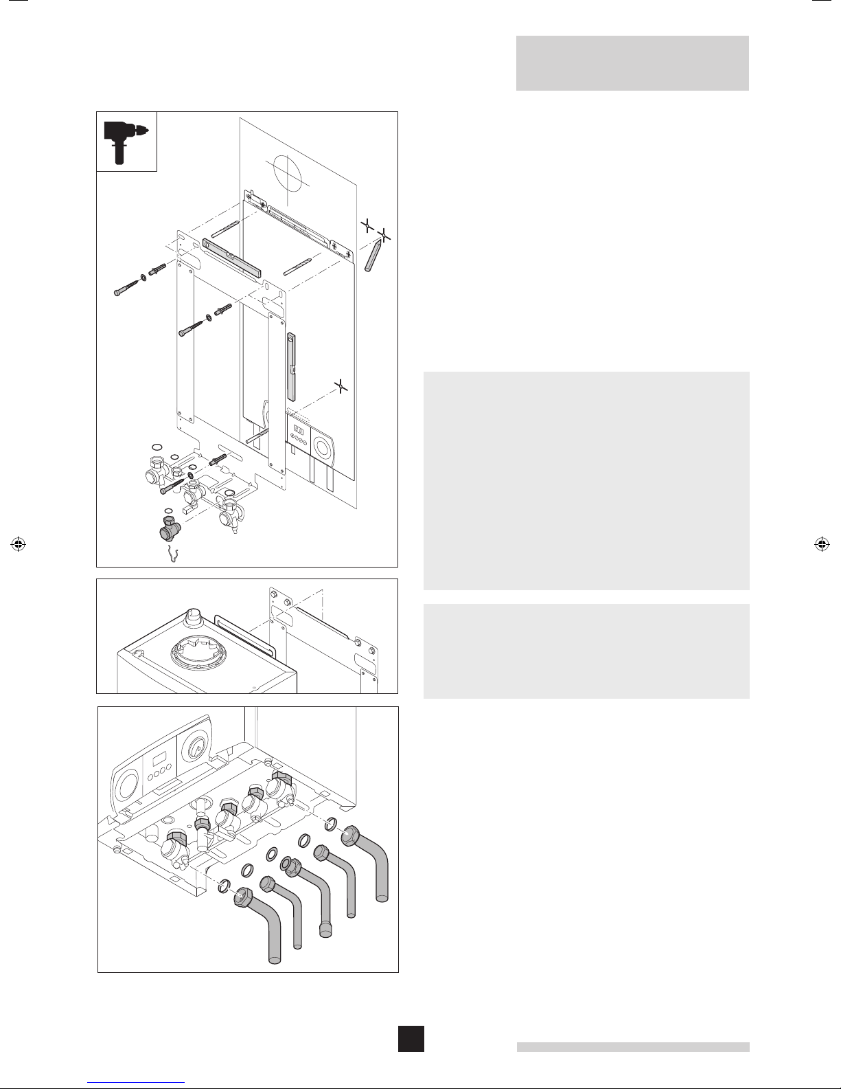
2.2.3 Mounting the Remeha Avanta Plus
• Remove the mounting plate and template from the box.
• Using the template determine and mark the position of the
three mounting holes and center line of flue, making sure
the plate is absolutely level.
• Drill the (Ø 10 mm) holes.
• Fit the (Ø 10 mm) plugs.
• Fit (Ø 8 mm) screws into the plugs.
• Check the mounting plate is level and tighten the screws.
• Fit the valve set to the mounting plate.
• Fit fibre washers on the CH valves.
• Remove boiler from the box and suspend it on mounting
plate.
• Connect the valves to the boiler remembering to fit fibre
washers supplied.
• Connect the supplied copper tails to the isolating valves.
• The boiler should be mounted on a suitable vertical wall
which is able to support the weight of the boiler.
• The boiler should be mounted in a room which, even during
severe cold weather, remains frost-free.
• If the boiler is to be installed in a timber framed building,
please refer to British Gas publication: ‘Guide for Gas
Installations in Timber frame Housing’, reference DM2.
• In a new installation it is possible to fit just the wall plate and
valve set to enable the system pipework to be completed
and tested before fitting the boiler at a later date (place
fibre washers supplied in a safe place for use when fitting
the boiler).
fi g. 07 Mounting the Avanta Plus
112952.LT.GB.W7H.012
• Make sure the boiler and any open connections are
protected from building dust etc. during the installation.
• There must be a 3 amp fused switched spur within 1m of
the boiler.
• Provision must be made for the condensate discharge.
2.3 Water-side connections
2.3.1 Water flow
An internal automatic flow by-pass is supplied in the Avanta
Plus to ensure correct operation on systems fitted with TRV’s
on all heat emitters. The ‘abc
perature difference across the flow and return connections and
the rate of temperature rise and will automatically regulate the
boiler output to ensure that it remains operational for as long
as possible without the need to ‘lock out’ requiring a manual
re-set.
®
’ control also monitors the tem-
10

600
500
400
300
200
Residual head [mbar]
100
0
0 200 400 600 800 1000 1200
Residual head UPR 15-60
dT 20°C 18kW
Pump 'high'
Pump 'low'
CH-flow [l/h]
fi g. 08 Graph residual head UPR 15-60 for the CH installation with
Avanta Plus 18s, 24s, 30s, 24c and 28c
LT.AL.W7H.000.013
700
600
500
400
300
Residual head [mbar]
200
100
0
0 200 400 600 800 1000 1200 1400 1600
Residual head UPR 15-70
Pump 'high'
Pump 'low'
CH- flow [l/h]
dT 20°C 28kW
fi g. 09 Graph residual head UPR 15-70 for the CH installation with
Avanta Plus 35c and 39c
LT.AL.W7H.000.014
2.3.2 Circulation pumps
The Remeha Avanta Plus 18s, 24s, 30s, 24c and 28c are fitted
with the Grundfos UPR 15-60 and the Avanta Plus 35c and
39c with the UPR 15-70, two-speed circulation pumps. The
control unit ensures that when the hot-water function is active,
the pump runs at ‘high’. The factory setting of the pump for CH
function is ‘low.’ If necessary, the service installer can adjust
this to ‘high’ by switching parameter 21 (from 0 to 1) see
par. 2.9.8.
2.3.3 Additional guidelines for the domestic and CH
water
• The system should be filled with mains cold water (for the
UK this will usually have a pH of between 7 and 8).
• Flush the pipes and radiators thoroughly to remove all fluxes
and debris before connecting the boiler to the central heating system.
• The temperature of the central heating pipes and the
radiators can rise to 95°C.
• Use untreated tap water only to fill the CH system.
• The pH value of the system water must be between 6 and 9
• In case inhibitors are being used, please follow the
instructions given in par. 2.3.4.
2.3.4 Water treatment
If used correctly water treatment can improve the boilers
efficiency and increase the anticipated life expectancy of the
boiler. For further information a special document “Quality
requirements CH water” is available from Broag.
As most systems contain a variety of metals, it is considered
good practice to provide some form of water treatment in order
to prevent or reduce the following:
• Metallic corrosion
• Formation of scale and sludge
• Microbiological contamination
• Chemical changes in the untreated system water
All scale deposits however small will reduce the efficiency of
the boiler and should be prevented.
Suitable chemicals and their use should be discussed with a
specialist water treatment company prior to carrying out any
work (environmental aspects, health aspects). The specification of the system and manufacturers recommendations must
be taken into account, along with the age and condition of
the system. New systems should be flushed thoroughly to
BS 7593(1992) to remove all traces of flux, debris, grease
and metal swarf generated during installation. Care to be
taken with old systems to ensure any black metallic iron oxide
sludge and other corrosive residues are removed, again by
power flushing, ensuring that the system is drained completely
from all low points.
11

Remeha Avanta Plus
Please ensure that the new boiler plant is not in circuit when
the flushing takes place, especially if cleansing chemicals are
used to assist the process.
It is important to check the inhibitor concentration after installation, system modifications, filling the system and every service
in accordance with these instructions.
For the correct dosage and the suitability of inhibitors for use
with our boilers and for further information on water treatment
or system cleaning we advise direct contact with either of the
following companies:
®
’ manufactured by:
‘F1
Fernox, Cookson Electronics
Forsyth Road
Sheerwater
Woking
Surrey GU21 5RZ
Tel No: 01483 793200
Fax No: 01483 793201
Email: admin@fernox.com
Web site: www.fernox.com
or:
Sentinal ‘X100
Sentinel Performance Solutions
The Heath Business & Technical Park
Runcorn
Cheshire,
WA7 4QX
Tel No: 0800 389 4670
Fax No: 0800 389 4677
Email: info.uk@sentinel-solutions.net
Web site: www.sentinel-solutions.net
2.3.5 Safety valve discharge
A pressure relief safety valve is fitted in the boiler set to the
maximum operating pressure of the boiler of 3 bar.
If the pressure in the boiler becomes too high the pressure
is relieved by releasing water to outside via the safety valve
discharge pipe. The discharge pipe should be fitted in accordance with British Standards and must be at least 15 mm Ø.
The pipe should be positioned so that the discharge of water
or steam is visible and cannot create a hazard to the occupants of the premises or damage the electric components and
wiring. In addition the discharge should be located where it is
unlikely to cause damage to the premises.
®
’ manufactured by
12
2.3.6 Expansion vessel
An 8 litre expansion vessel (with the vessel charge set to 1.0
bar) is fitted as standard within the boiler case and is suitable
for use in a heating system with a water content up to 100
litres, operating at a flow temperature of 80°C, a maximum
pressure of 3 bar and a maximum system static head of 5
metres above the boiler. If the system water content is greater
than 100 litres, or the system static head above the boiler is
greater than 5 m, an additional vessel must be installed in the
system to allow for the increase in expansion, see table 01.
Install additional vessel according BS 5449, part1.
Boiler Safety Valve Setting
(Bar) 3.0
Vessel Charge (Bar) 0.5 1 1.5
Heating System Water Content
(Litres)
Expansion Vessel Size
(Litres)
100 4.8 8.0 13.3
125 6.0 10.0 16.6
150 7.2 12.0 20.0
175 8.4 14.0 23.3
200 9.6 16.0 26.6
250 12.0 20.0 33.3
300 14.4 24.0 39.9
For other system volumes, mul-
tiply the system volume by the
0.048 0.080 0.133
factor across:
table 01 Expansion Vessel Size
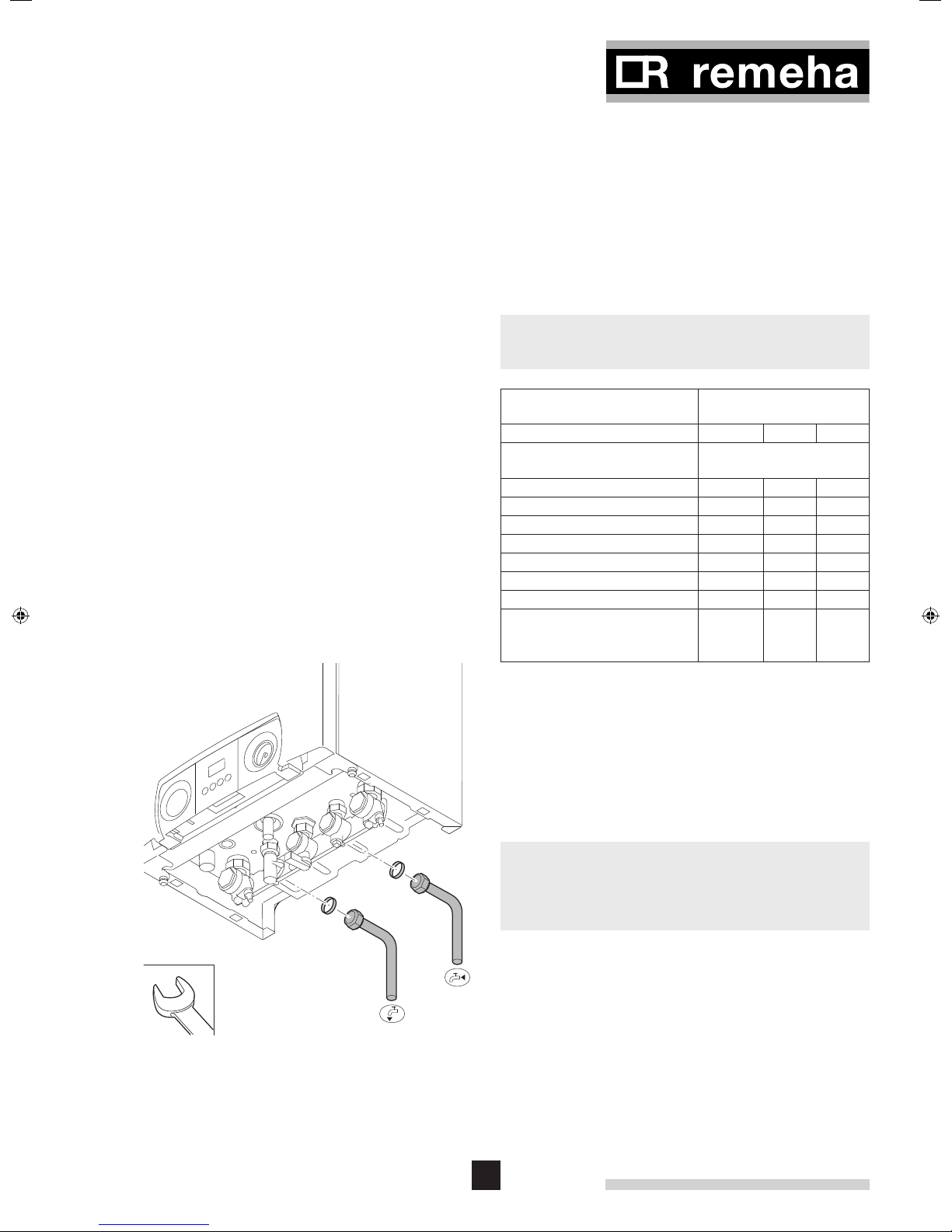
fi g. 10 Connecting DHW pipes
LT.AL.W7H.000.015
2.3.7 Connecting DHW pipes
(For combi type only)
• Fit the outlet pipe for hot water to the DHW outlet 15
mm Ø connection.
• Fit the inlet pipe for cold water to the DHW inlet 15 mm
Ø connection.
• The DHW pipes must be connected in accordance with
current regulations.
• For plastic pipes, follow the manufacturer’s instructions
(for connection).
13

Remeha Avanta Plus
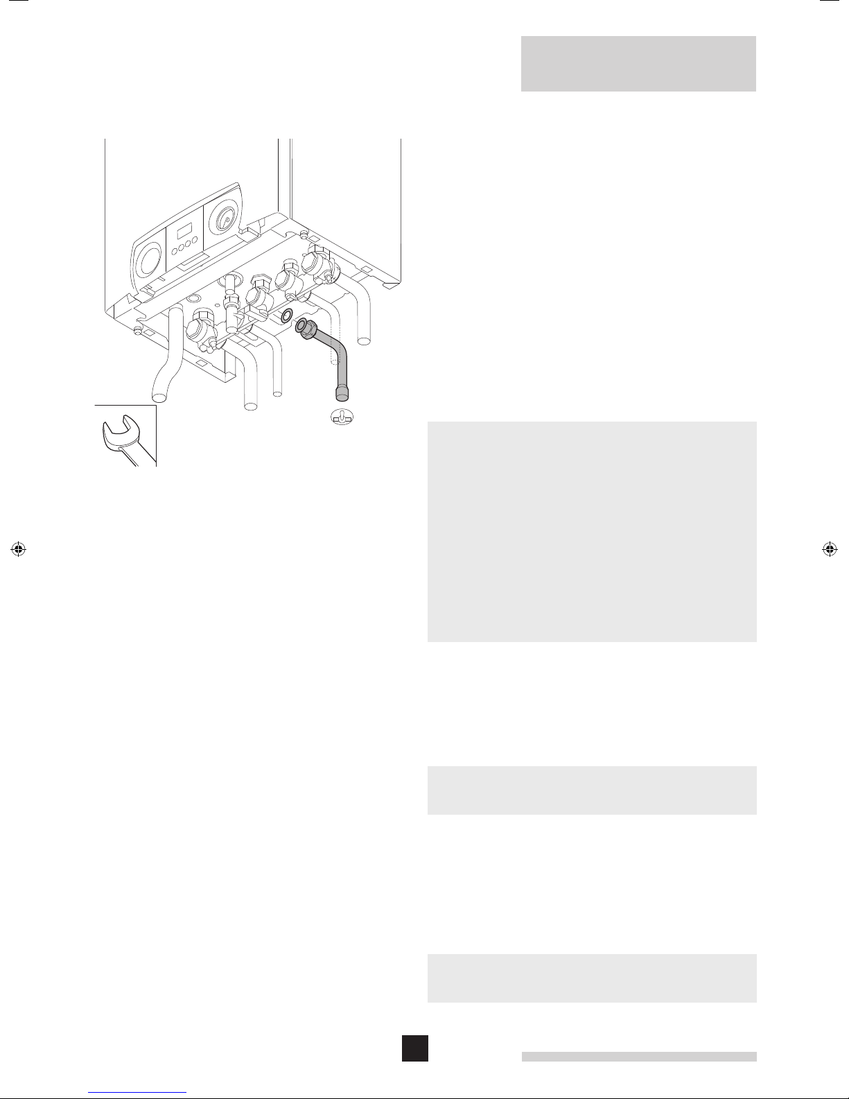
2.3.8 Connecting the ‘CH return’
• Fit the inlet pipe for CH water to the ‘CH return’ 22 mm
Ø connection.
The Remeha Avanta Plus has a drain cock built into the return
isolating valve
It is considered good practice to install an air separator / dirt
removal device in the return to the boiler.
fi g. 11 Connecting CH return
LT.AL.W7H.000.016
2.3.9 Connecting ‘CH flow’
• Fit the outlet pipe for CH water to the ‘CH flow’ 22 mm
Ø connection.
The Remeha Avanta Plus has a drain cock built into the flow
isolating valve.
fi g. 12 Connecting CH fl ow
LT.AL.W7H.000.017
14

fi g. 13 Connecting condensate drain
LT.AL.W7H.000.018
2.3.10 Connecting condensate drain
• Connect the condensate drain outlet to a suitable waste
water drain point using acid resisting pipe work (i.e. - ¾”
overflow). To enable the siphon in the boiler to be removed
/ serviced, the connection should not be a permanent one
(i.e. “push fit” system).
• To prevent the risk of freezing connect the condensate into
an internal vertical soil pipe using a tundish (air break) c/w a
min 75 mm water seal trap.
• If the condensate pipe has to run externally make sure
this is done by realizing the shortest possible route, and
increase the diameter to at least 1¼” or insulate it with
weather resistant insulation.
• The drain should slope at least 3 cm per meter, with a maxi-
mum horizontal length of 5 m.
• If connecting into an internal discharge branch (i.e. sink
waste etc.) the connection should preferably be down
stream of the existing waste trap.
• Fill the boiler siphon with water before operation, to prevent
flue gasses discharging into the room.
• The condensate drain must be connected in accordance
with current regulations.
2.3.11 Connecting under floor heating
The Remeha Avanta Plus can be connected directly to an
under floor heating system.
If plastic pipes have been used they must be made oxygen diffusion proof in compliance with DIN 4726/4729
When installing under floor heating with a separate pump, the
layout should be such that the under floor heating pump cannot cause a flow to the boiler if there is no heat demand. A low
loss header should therefore be fitted between the system and
the boiler.
Please ensure that the residual pump duty of the boiler is
sufficient for the resistance of the under floor system. If not a
low loss header should be used to separate the boiler from
the under floor circuit to allow a separate pump sized for the
resistance of the under floor system to be used.
2.4 Gas-side connections
2.4.1 Additional guidelines for gas connections
Before installation, check that the gas meter has sufficient
capacity for the demand. Remember to consider the
consumption of all household appliances.
15
fi g. 14 Connecting gas supply
LT.AL.W7H.000.019
Remeha Avanta Plus
2.4.2 Adjusting boiler to other gas-type
The Avanta Plus boilers are suitable for both natural gas and
propane firing. For propane a kit with restrictor is required.
For Avanta Plus 39c a LPG conversion set with restrictor and
burner is needed.
The boilers are supplied as standard set for natural gas
(G20), therefore the following procedure must be carried out
BEFORE the boilers are fired and commissioned for the first
time on propane:
Fit the conversion kit (instructions included in kit)
Adjust the fan speed (see Par. 2.9.8) and adjust the gas/air
ratio (see Par. 2.9.3).
2.4.3 Connecting the gas supply
• Before starting any work on the gas supply, turn off the main
isolation valve.
• Connect the gas supply to the 22 mm Ø boiler
connection.
• Make sure there is no dirt in the gas pipe. Blow through the
pipe before installation or tap well to purge.
• The principle of the 1:1 gas valve ensures the Avanta range
is able to deliver it’s full output at inlet pressure down to 17
mbar. However if dynamic pressure below 19 mbar are
experienced ensure this is adequate for ALL other gas
appliances in the property.
• Preferably install a gas filter in the gas pipe to prevent the
gas block from getting dirty.
• The gas supply must be connected, tested for soundness
and purged by a qualified Engineer and in accordance
with BS6891.
2.5 Flue terminal and air supply connections
The Remeha Avanta Plus is only suitable for room sealed
operation with a standard concentric connection 60/100 mm Ø
or the optional 80/125 mm Ø connection.
Detailed recommendations for air supply and flue terminals are
given in BS 5440.
It should not be necessary to provide compartment ventilation
when the boiler is used with a standard concentric flue.
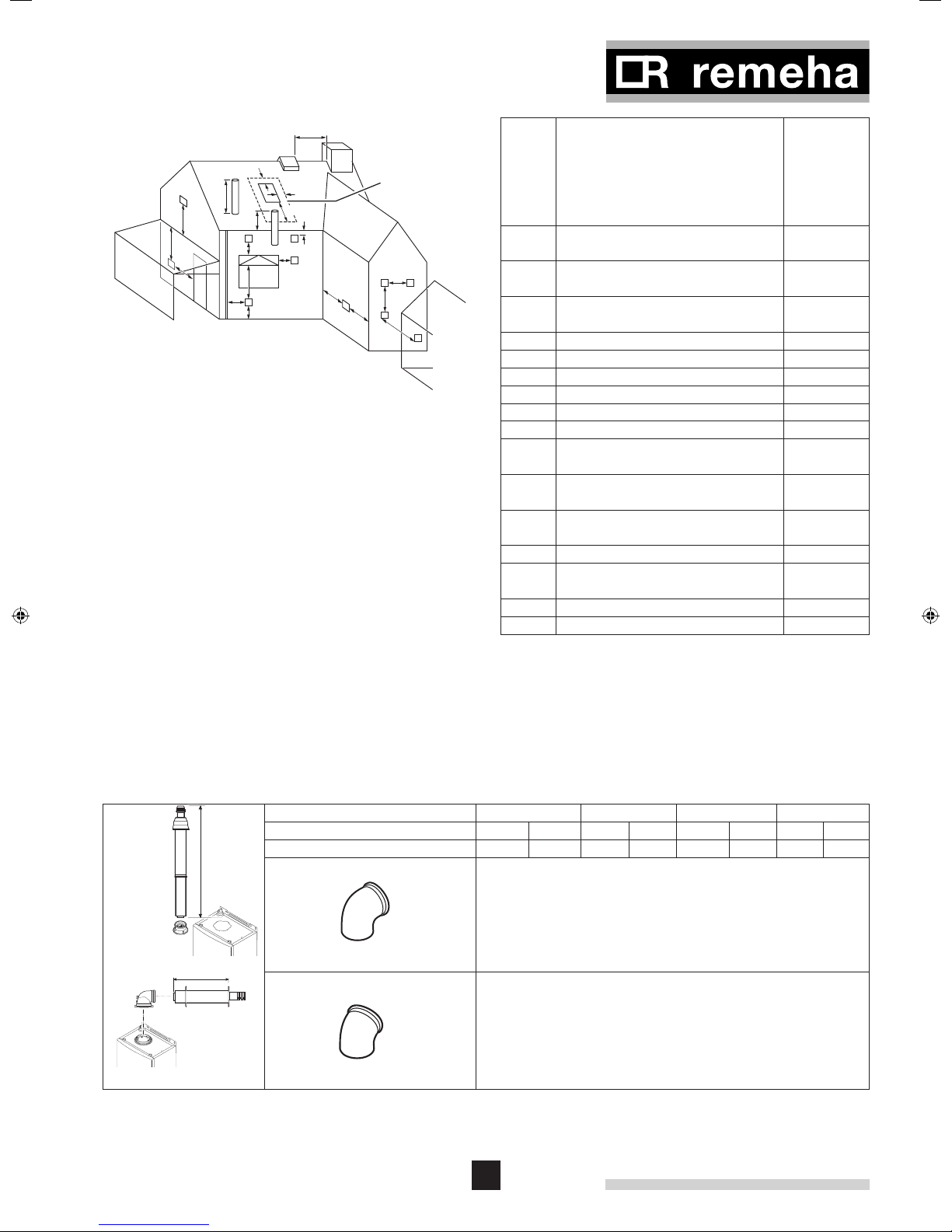
2.5.1 Flue terminal positions
The flue terminal must be located with care to ensure that the
products of combustion are dispersed properly in all weather
conditions and cause minimum nuisance to the building user
or any adjacent buildings. If the terminal is positioned less
than 2 m above the ground, balcony, or flat roof where access
by persons is possible a suitable guard must be employed.
The boiler will produce a water vapour plume during normal
operation.
Positions for the Remeha Avanta
and table 02.
16
Plus are shown in the figure
600 mm
S
G
F
P
S
B
A
H
G
fi g. 15 Flue terminal positions
LT.AL.W7H.000.020
600 mm
2000 mm
C
D,E
A
Dimensions
No flue must penetrate
area within dotted lines
round roof light
Terminal location Minimum
distance
(in mm) to
terminal
(room sealed)
A Directly below an opening, air brick,
opening window, etc.
J
M
L
J
K,N
B Above an opening, air brick, opening
window, etc.
C Horizontally to an opening, air brick,
opening window, etc.
D Below a gutter or sanitary pipe work 75
300
300
300
E Below the eaves 200
F Below a balcony or carport roof 200
G Above ground, roof or balcony level 300
H From vertical drain/soil pipe work 150
J From an internal or external corner 300
K From a surface or boundary facing
the terminal
L Vertically from a terminal on same
wall
M Horizontally from a terminal on same
wall
1500
1500
300
N From a terminal facing the terminal 1200
P From an opening in a carport (e.g.
door, window) into the building
1200
R From a vertical structure on the roof n/a
S Above an intersection with the roof 300
VRS roof
mounted
room sealed
terminal
L
112952.LT.GB.W7H.065
112952.LT.GB.W7H.066
L
80/125 or 60/100
+
Diameter in mm Ø
Maximum length ‘L’ allowed [m]
Eq. Length of 90° elbow
LT W6H 000 031
Eq. Length of 45° elbow
LT W6H 000 032
table 02 Minimum distances to terminal
n/a = not applicable.
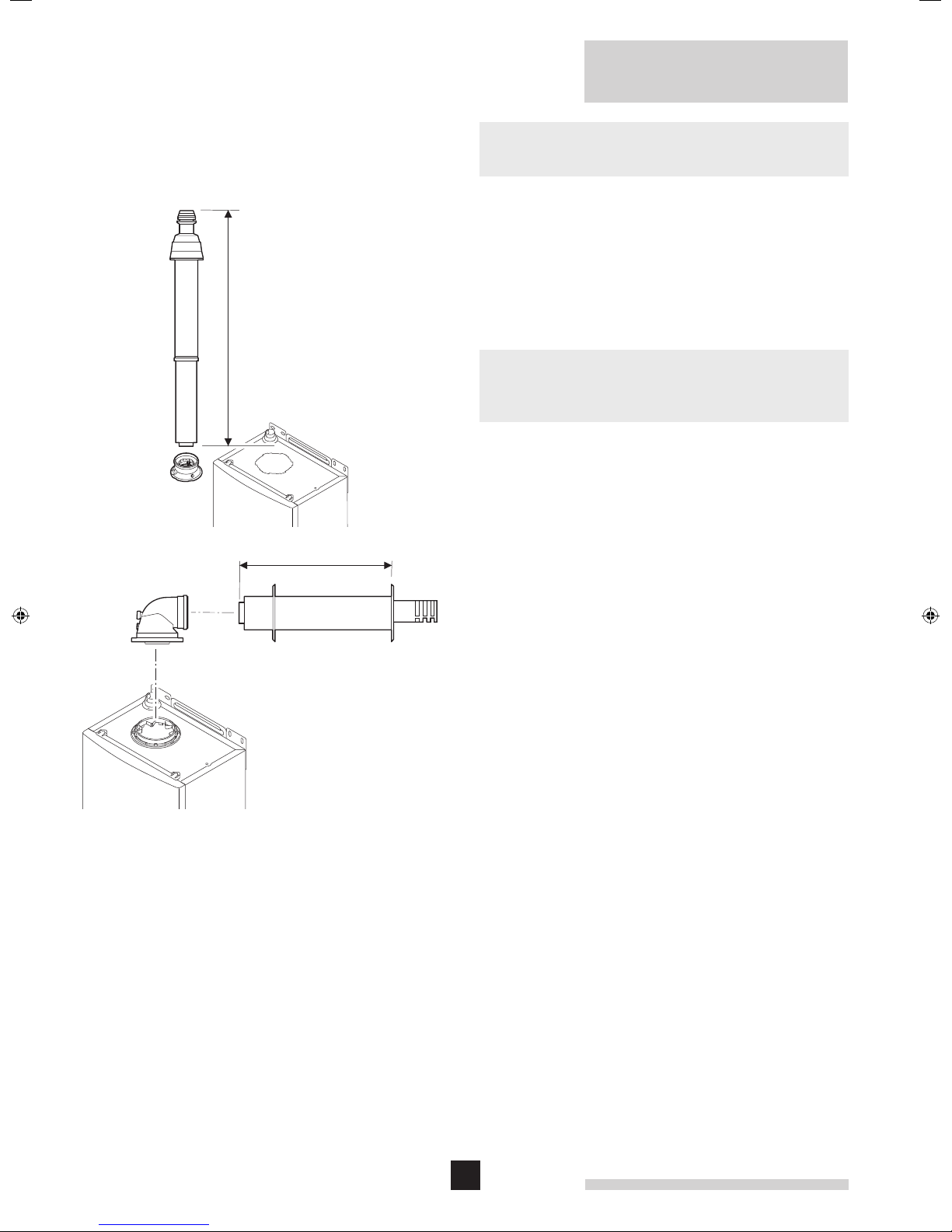
2.5.2 Room sealed flue
See table 03 for the maximum pipe length of flue ducts and air
supply pipes for this ‘room sealed’ application.
It is not necessary to provide combustion air to the room or
internal space in which the boiler is installed.
18s/24s/30s 24c/28c 35c 39c
60/100 80/125 60/100 80/125 60/100 80/125 60/100 80/125
6 29 6 29 7 30 5 25
1.4
0.65
table 03 Maximum pipe lengths for fl ue duct and air supply
in room sealed application
17
L
VRS roof
mounted
room sealed
terminal
Remeha Avanta Plus
For flue installations not covered by this booklet, please
contact our technical help line 0118 978 3434.
2.5.3 Connecting the flue terminal and air supply
• How to install the horizontal or vertical flue terminal and air
supply kits; please take note of the mounting instructions
supplied with it.
• All connections must be airtight and waterproof.
• Horizontal extension sections should slope towards the
boiler (at least 3 cm per metre).
L
80/125 or 60/100
fi g. 16 Connecting fl ue terminal and air supply
112952.LT.GB.W7H.065 + 112952.LT.GB.W7H.066
18
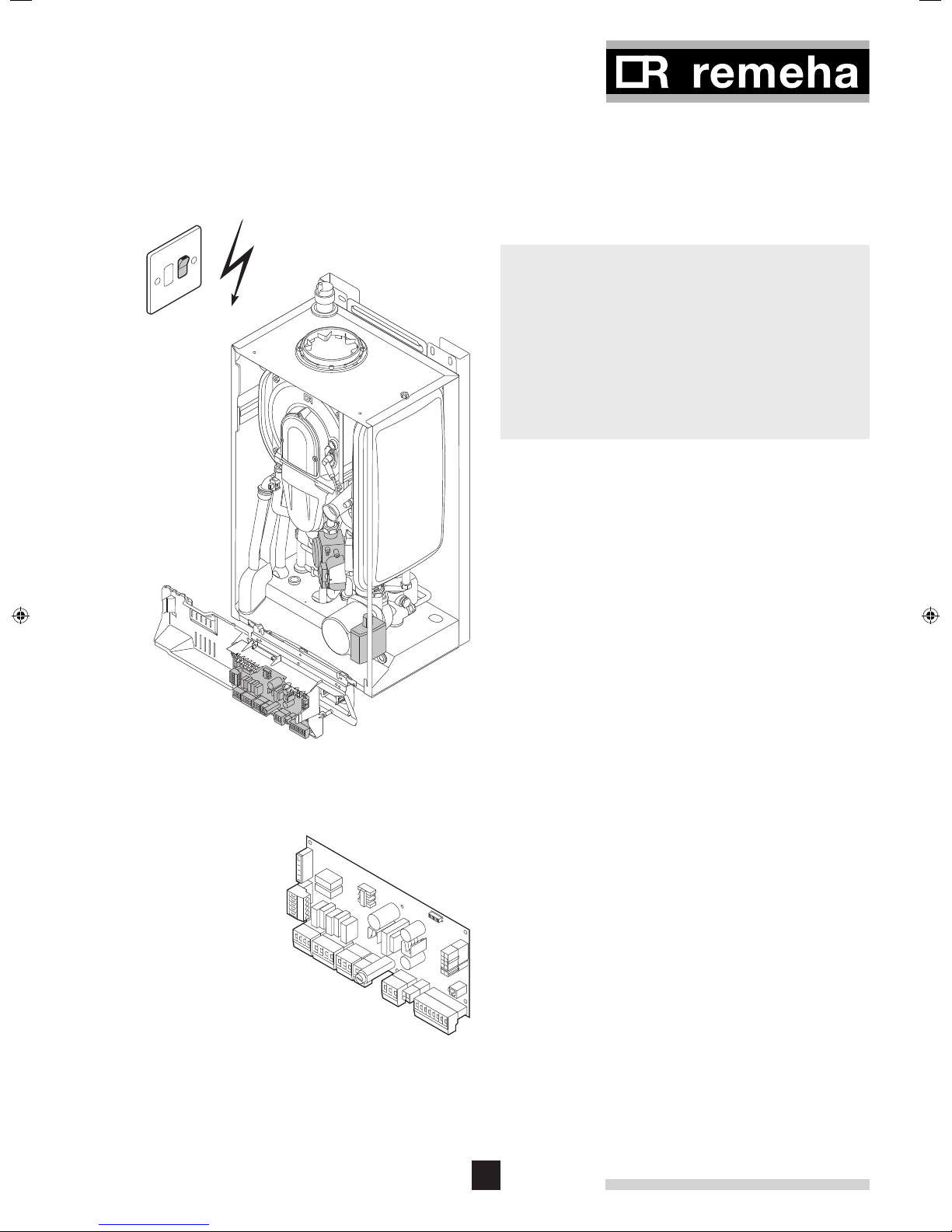
230 V
2.6 Electrical connection
• Connect the boiler to the fused (3 amp) switch spur unit
adjacent to boiler.
• The switch unit must always be accessible.
When the switch spur is on the following components of this
appliance can be live (230 V):
• electrical connection pump;
• electrical connection gas combination block;
• electrical connection three-way valve;
• most parts of the control unit;
• ignition transformer;
• X1, X2, X4, X5, X6 and X7 terminal block;
• 230 V supply cable connection.
fi g. 17 Electrical components with live 230 V
112952.LT.GB.W7H.022
fi g. 18 The control unit
LT.AL.W7H.000.023
2.6.1 The control unit
The Remeha Avanta Plus has an electronic regulation and
control unit with an integrated ionisation flame detector. The
heart of the boiler control unit is a microprocessor, the ‘abc
which controls and protects the boiler.
The maximum rated input is between 115 and 180 W (depending on boiler type).
The boiler is fully pre-wired internally, all external connections
can be made using the terminal blocks X5 - X7 - X9 and 230
V input (X2 terminal). See the diagram for the position of the
connectors and fuse (F2) on the control unit.
The most important properties of the control unit are summarized in table 04.
19
®’
,
Remeha Avanta Plus
Manufacturer Sit Controls
Supply voltage 230 V – 1ph – 50 Hz
Pre-purge time 3 s
Post-purge time 5 s
Ignition time 2.5 s
Safety time 5 s
Anti-cycling time 3 till 10 min.
Fuse value F1 (230 V) 2 AT
DC fan 24 VDC
table 04 Control unit characteristics
Any loads other than those specified above are only allowed if
an isolating transformer is used.
The output of the Remeha Avanta Plus can be controlled in
the following ways: Options
1. On/off control – volt free switching - The boilers internal
control will modulate the output to achieve the flow temperature set point of the boiler. This contact is on the connectors 7 and 8 on terminal block X9 (low voltage only).
2. Modulated control – Open Therm - The external controls
will modulate the boiler’s output to achieve the flow temperature determined by the modulating regulator. This contact
is on the connectors 7 and 8 on terminal block X9 (low voltage only).
2
3. On/off control – 230 V switching - The boilers internal
control will modulate the output to achieve the flow temperature set point of the boiler. This contact is on the connector
1 on terminal block X2 (230 VAC only).
4.
Modulated control – Open Therm in combination with an
externally mounted simple 230 V switching time clock -
The boiler will provide room compensated heating and time
control over CH and DHW (System boiler), use options 1 & 2.
1
fi g. 19 Connecting external controls
LT.AL.W7H.000.024
• All connections on terminal X1, X2, X4, X5, X6 and X7
are 230 VAC.
• All connections on terminal X9 are low voltage only.
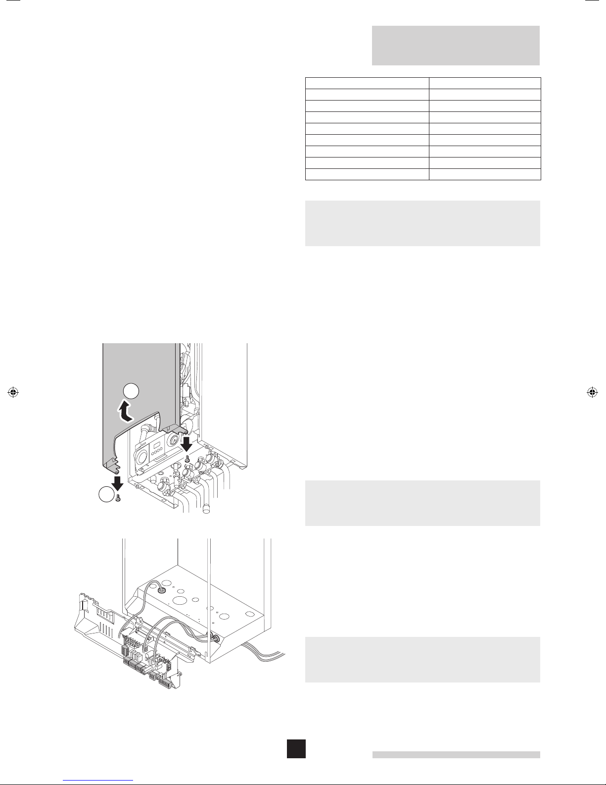
2.7 Connecting external controls
• Release the two screws at the bottom of the front casing
and remove the front casing.
• Feed the cables through the grommet in the base of the
boiler.
• Connect the cables to the relevant connectors, as shown in
the diagrams.
• Isolate power supply at the fused spur before carrying out
any work on the boiler controls.
20
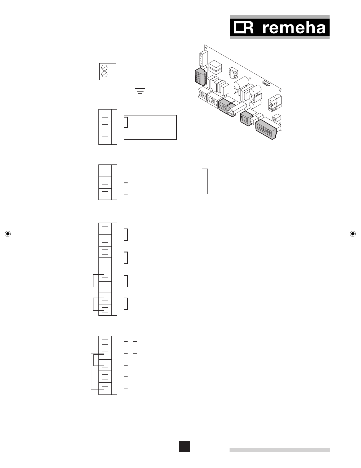
Terminal
Block X6
L
N
Terminal
Block X7
230v - 3 Amp
Power Supply
E
X2
Exist
links
Terminal
Block X5
Terminal
Block X9
1
Common Alarm
(Closes on alarm)
2
3
1
2
3
1
2
3
4
5
6
7
8
Neutral
Open valve to DHW (230v)
Open valve to HTG (230v)
Outside sensor (red band) for direct boiler weather compensation
or when used in conjuction with a compatable Open Therm
control eg: Chronotherm or Celcia 20
DHW sensor (red band) or volt free thermostat (make on temp fall)
Remove existing link to use this function
External interlock (volt free)
Remove existing link to use function
Modulating - using Open Therm control
eg: Honeywell Chronotherm or Celcia 20
On / Off - using volt free switching control
eg: Celcia 10 or low volt room thermostat
X5
Boiler Run or
external pump relay
(Closes on run)
For external DHW priority
diverting valve on System boiler
when used in conjunction with
"Open Therm" compensation
X6
X7
X9
Terminal
Block X2
54N
3
Exist
links
2
1
Power supply to external time clock -230v
L
Switch live (230v) from external time clock DHW demand
Remove existing link 4-3 to use this function
Switch live (230v) from external time clock HTG demand
Remove existing link 4-1 to use this function
NOTE: Terminal blocks are not in line as shown - diagramatic only
fi g. 20 Boiler External Connection terminal details
LT.AL.W7H.000.025f
21
Terminal
Block X9
1
2
3
4
Exist
links
5
6
7
Modulating - using Open Therm control
eg: Honeywell Chronotherm or Celcia 20
On / Off - using simple volt free switching control
8
fi g. 21 Wiring diagram on/off control
LT.AL.W7H.000.026c
X9
Remeha Avanta Plus
2.7.1 On/off control – room temperature (volt free
switching)
The Remeha Avanta Plus can be connected to a 2-wire on/
off volt free heating control, programmer or thermostat, ie
Remeha Celcia 10. Mount the thermostat in a reference room
usually the living room.
• Remove existing link between connectors 7 and 8 of the X9
terminal block before use;
• Connect the 2-wire programmer or room thermostat to
connectors 7 and 8 of the X9 terminal block.
If a room thermostat with an anticipation resistor is being used,
parameter p5 should be changed from 0 to 1, see par.
2.9.8.
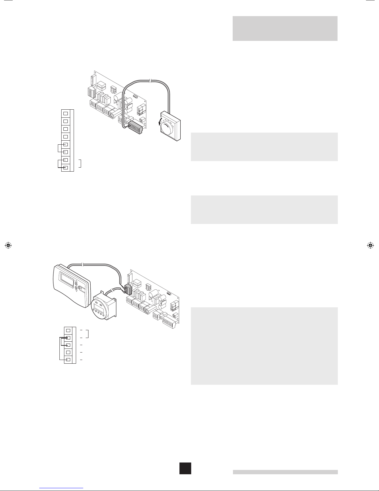
2.7.2 Time control using an internal or external
230 V clock
When the switch spur is on, the terminal block X2 will be live
(230 V).
X2
Terminal
Block X2
5
Power supply to external time clock -230v
4NL
Switch live (230v) from external time clock DHW demand
3
Exist
links
Remove existing link 4-3 to use this function
2
Switch live (230v) from external time clock HTG demand
1
Remove existing link 4-1 to use this function
fi g. 22 Wiring diagram for an external 230 V time clock
LT.AL.W7H.000.027
• A 230 V two channel time clock for CH and DHW control
can be connected to the Remeha Avanta Plus
.
Live 230 V supply for the time clock - connect to connectors
4 (L) and 5 (N) on X2 terminal block.
• For CH - remove existing link between connectors 4 and 1
of the X2 terminal block and connect the 230 V output from
the time clock to terminal 1 on the terminal block X2.
• For DHW - remove existing link between connectors 4 and 3
of the X2 terminal block and connect the 230 V output from
the time clock to terminal 3 on the terminal block X2.
For this option to function correctly a link or room control must
be fitted between connectors 7 and 8 of X9 terminal block
(remove existing link before use).
For continuous DHW on, when using a combi boiler, the link
across connectors 3 and 4 MUST NOT be removed
If the 230 V supply for the external time clock is not taken from
the boiler – terminal block X2 connections 4 & 5, it must be
taken from the same phase as the boiler 230cv supply and
correct polarities observed.
22
 Loading...