

REMEHA Avanta Plus 35c, Avanta Plus 28c, Avanta Plus 39c, Avanta Plus 24s Installation And Service Manual
1
• Remeha Avanta Plus 28c
• Remeha Avanta Plus 35c
• Remeha Avanta Plus 39c
• Remeha Avanta Plus 24s
Remeha Avanta Plus
Installation and service manual
Remeha Avanta Plus

2
Remeha Avanta Plus
INTRODUCTION
1 SAFETY 5
1.1 General safety 5
1.2 Safety during assembly and installation 5
1.3 Safety during installation, inspection and maintenance 5
2 INSTALLATION 7
2.1 Scope of delivery 7
2.2 Mounting the boiler 7
2.2.1 Clearance requirements 7
2.2.2 Dimensions and connection points. 8
2.2.3 Mounting the Remeha Avanta Plus 10
2.3 Water-side connections 10
2.3.1 Water fl ow 10
2.3.2 Circulation pumps 11
2.3.3 Additional guidelines for the domestic and CH water 11
2.3.4 Water treatment 11
2.3.5 Safety valve discharge 12
2.3.6 Expansion vessel 13
2.3.7 Connecting DHW pipes (Combi-type only) 13
2.3.8 Connecting the ‘CH return’ 14
2.3.9 Connecting ‘CH fl ow’ 14
2.3.10 Connecting condensate drain 15
2.3.11 Connecting under fl oor heating 15
2.4 Gas-side connections 15
2.4.1 Additional guidelines for gas connections 15
2.4.2 Connecting the gas supply 16
2.5 Flue terminal and air supply connections 16
2.5.1 Flue terminal positions 16
2.5.2 Room sealed fl ue 17
2.5.3 Connecting the fl ue terminal and air supply 18
2.6 Electrical connection 19
2.6.1 The control unit 19
2.7 Connecting external controls 20
2.7.1 On/off control – room temperature (volt free switching) 22
2.7.2 Time control using an internal or external 230 V clock 23
2.7.3 Connecting a 230 V time clock in combination with a modulating room control 23
2.7.4 Modulating control – room or outside compensation 23
2.7.5 Connecting an outside temperature sensor 24
2.7.6 Connecting the DHW sensor/thermostat 25
2.7.7 Connecting a frost protection device 25
2.7.8 Connecting an external interlock 26
2.7.9 Connecting remote alarm and boiler run indication 26
2.7.10 Connecting a PC/PDA 26
2.8 Wiring diagram 27
2.9 Commissioning 27
2.9.1 Control Panel 27
2.9.2 Additional guidelines for commissioning 27
2.9.3 Putting the boiler into operation 27
2.9.4 Normal start-up procedure 33
2.9.5 Error during the start-up procedure 33
2.9.7 Adjust the boiler according to the system 35
2.9.8 Changing the parameters at service level (with access code) 35
2.9.9 Changing the maximum output (Hi) for CH operation 37
2.9.10 Restore factory settings 39

3
2.10 Putting the boiler out of operation 39
2.10.1 Boiler with frost protection, during longer periods of non-use 39
2.10.2 Boiler without frost protection, during longer periods of non-use 39
3 INSPECTION AND MAINTENANCE 40
3.1 Inspection 40
3.1.1 Checking the water pressure 41
3.1.2 Checking the fl ue pipes and air supply pipes for leaks 41
3.1.3 Checking the condensate siphon 42
3.1.4 Checking the ignition electrode 42
3.1.5 Checking the combustion 42
3.2 Maintenance 43
4 ERRORS 49
4.1 General 49
4.2 Error codes 49
4.3 Control stop or shut down 51
4.4 Error memory 51
4.4.1 Error read outs 52
4.4.2 Deleting errors 52
5 SERVICE PARTS 53
5.1 General 53
6 EC DECLARATION 56
7 REGULATIONS 57
7.1 EC regulations 57
7.2 Remeha factory test 57
8 TECHNICAL SPECIFICATIONS AND WORKING PRINCIPLE 58
8.1 Technical data 58
8.2 The boiler components 59
8.3 Working principle 59
8.3.1 Regulating 60
8.3.2 Advanced boiler control (‘abc
®
’-control) 60
8.3.3 Regulating the water temperature 61
8.3.4 Low fl ow / water protection 61
8.3.5 High Limit temperature protection 61
9 EFFICIENCY DATA AND GAS EFFICIENCY LABELS 62
9.1 Annual effi ciency 62
9.2 Water-side effi ciency 62
4
Remeha Avanta Plus
INTRODUCTION
The Remeha Avanta Plus is a series of high-efficiency fully
condensing central heating boilers, for wall mounting,
available in the following types:
• Remeha Avanta Plus 28c, 35c and 39c
- with integrated domestic hot water system (Combi-type)
• Remeha Avanta Plus 24s
- without integrated domestic hot water system
(System-type)
LT.AL.W7H.000.001
These technical instructions contain useful and important information for the correct installation, operation and maintenance
of the Remeha Avanta Plus combi and system boilers.
o
Read these instructions carefully before putting the boiler into
operation, familiarise yourself with their control functions and
operation, strictly observing the instructions given. Failure to
do so may invalidate warranty or prevent the boiler from
operating correctly.
The installation, commissioning, inspection and servicing of the
boiler must be carried out by a competent Corgi registered engineer who holds valid ACOPS certification and in accordance
with current gas safety (installation and use) regulations, the
building regulations and all other relevant codes of practice.
All electrical work must be carried out by a competent engineer and to be installed in accordance with the current IEE
regulations.
o
On commissioning the certificate in the Boiler Service Log
book (supplied with the boiler) must be completed and left on
site with a copy send on to Broag Ltd for registration purposes.
If you have any questions, require an engineer to call on site,
or if you need more information about specific subjects relating
to this boiler, or it's installation please do not hesitate to contact our technical help line 0118 978 3434.
o
When contacting Broag with a problem on the boiler, please
have available the boiler type, Serial No (located on the
bottom of the casing), and the symptoms or fault code (the
fault code is a series of flashing red digits in the display panel).
The data published in these technical instructions is based on
the latest information (at date of publication) and may be subject to revisions.
We reserve the right to continuous development in both design
and manufacture, therefore any changes to the materials or
technology employed may not be retrospective nor may we be
obliged to adjust earlier supplies accordingly.

5
1 SAFETY
1.1 General safety
The following pictograms are used in this Installation and Service manual to specifically draw certain points to your attention:
Tip o Useful tip or practical advice.
Indication z Important instruction in carrying out a
particular operation.
Warning m Possible danger of personal injury or
material damage to the regulator,
building or environment.
Danger { Serious personal injury can occur
because of risk of electric shocks.
1.2 Safety during assembly and installation
Observe the appropriate safety measures, as given in these
instructions.
m
Can you smell gas? What to do:
• do not smoke and do not create any flame or sparks;
• do not use any electric switches;
• turn off the gas tap;
• open windows and doors;
• trace possible leaks and seal them.
Warning! If the leak is before the gas meter, alert your gas
supplier, TRANSCO, tel. 0800 111 999
m
Can you smell smoke or flue gasses? What to do:
• isolate power supply.
• open windows and doors;
• trace possible leaks and seal them.
1.3 Safety during installation, inspection and
maintenance
Under the current Gas Safety (Installation & Use) Regulations,
the Remeha Avanta Plus, in common with all gas appliances,
must be installed by a competent person in accordance with
that regulation.
Statutory regulations in any country, cannot be overridden by
any of the notes or instructions from the manufacturer.
Compliance with National Standards does not provide any
degree of immunity from legal obligations. In the UK, the
installation must be in accordance with the national and local
norms and requirements.
For any issues or circumstances not addressed within these
instructions, please call our Customer Care Department.

6
Remeha Avanta Plus
The Remeha Avanta Plus (combi and system) is a WRAS
(Water regulations) approved product.
LT.AL.W7H.000.074
Remeha Avanta Plus (combi and system) - PIN:
0063BQ3009
Gas Council numbers: Remeha Avanta Plus 28c: 47-673-02
Remeha Avanta Plus 35c : 47-673-03
Remeha Avanta Plus 39c: 47-673-04
Remeha Avanta Plus 24s: 41-288-05
Classification type for evacuation of the combustion products;
according EN 483: see Par. 8.1.
Health and safety information
• The weight of the Avanta Plus system and combi boilers
exceed the maximum lift weight for one person.
• All sealants and gaskets are free from harmful products. On
first firing the boiler, a smell from the sealants and gaskets
may be present and should cease after a short period.
7
400
min.600
3
00
min. 250
min.
2
50
670
2 INSTALLATION
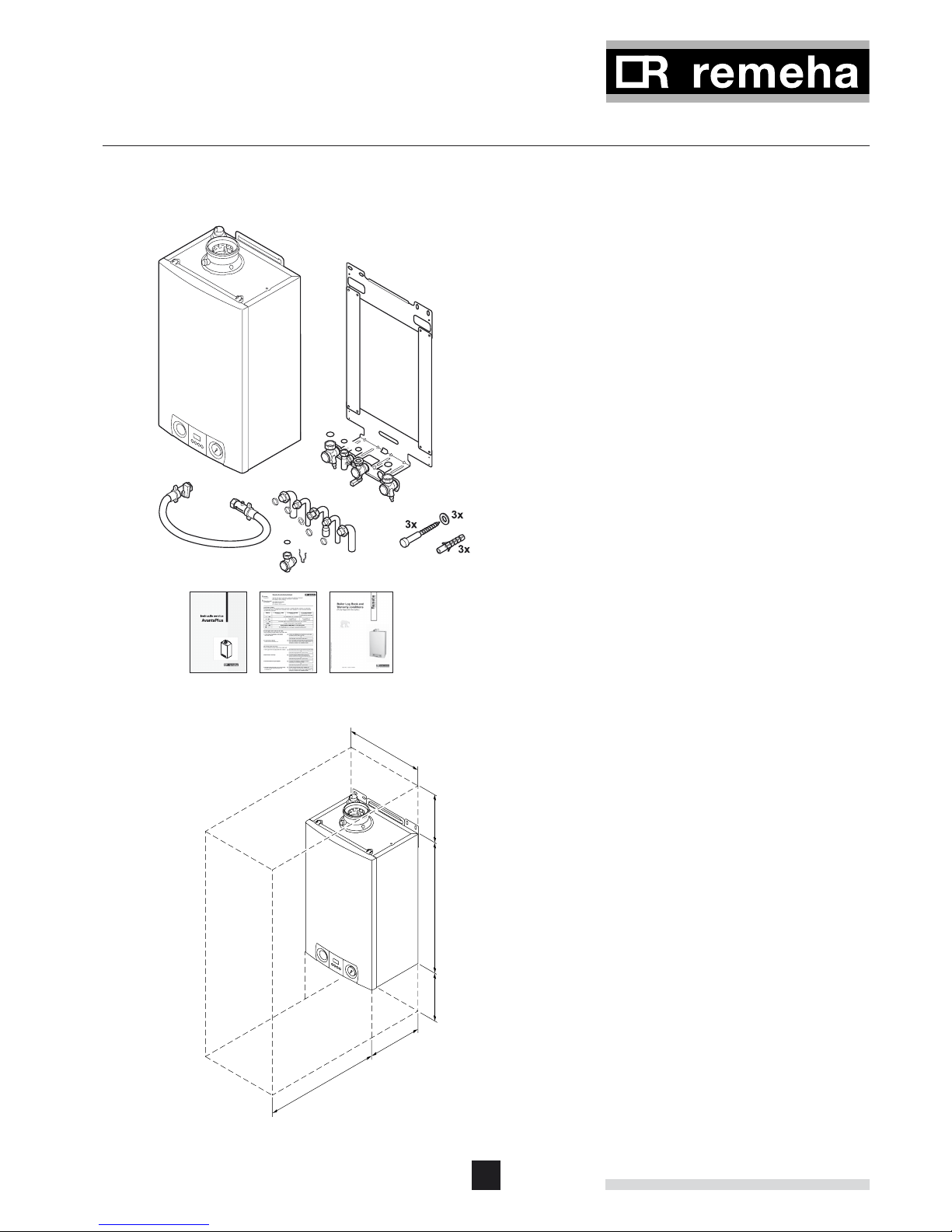
2.1 Scope of delivery
The standard delivery of the Remeha Avanta Plus boiler
includes:
LT.AL.W7H.000.011
- the boiler (including pressure gauge and safety valve);
- mounting plate (including isolation valve set and washers);
- nylon plugs and screws for fixing mounting plate;
- copper tails 15/22 mm;
- mounting template;
- filling loop;
- Boiler Service Log Book;
- Installation and Service manual and Users guide.
This Installation and Service manual deals with the standard
supplied boiler only. For the installation or assembly of any
optional accessories supplied with the boiler, such as stand off
frame, pipework kits, cover plate, control kits, etc, please refer
to the Assembly Instructions supplied with these accessories.
2.2 Mounting the boiler
Packed in the box with the Remeha Avanta Plus box is this
Installation and Service manual. Read instructions and remarks
carefully. This section includes the guidelines and instructions
for the connection of gas, water, electricity, safety devices, the
regulator, control unit, flue discharge and air supply.
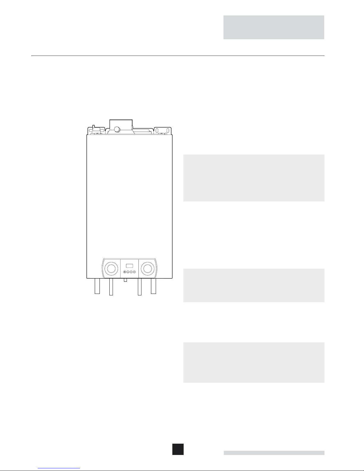
2.2.1 Clearance requirements
The gas and water connections are located on the bottom of
the boiler whilst the air in and flue gas outlet is located on the
top of the boiler. The boiler is supplied as standard with pipework tails to allow connections facing downwards.
Optional stand off frame and pipework kits are available
to enable the pipework to run upwards behind the boiler if
required. For installation, servicing and inspection min. 600
mm in front of the boiler is required. If this free space is
obtained by opening a door or removing a panel, the boiler
may be installed for instance in a closed cupboard.
We do recommend a side clearance of 0.5 cm so that the unit
is easy to open, with a free space of 25 cm under the appliance and 25 cm above the appliance, as the minimum requirement.
LT.AL.W7H.000.003
8
Remeha Avanta Plus
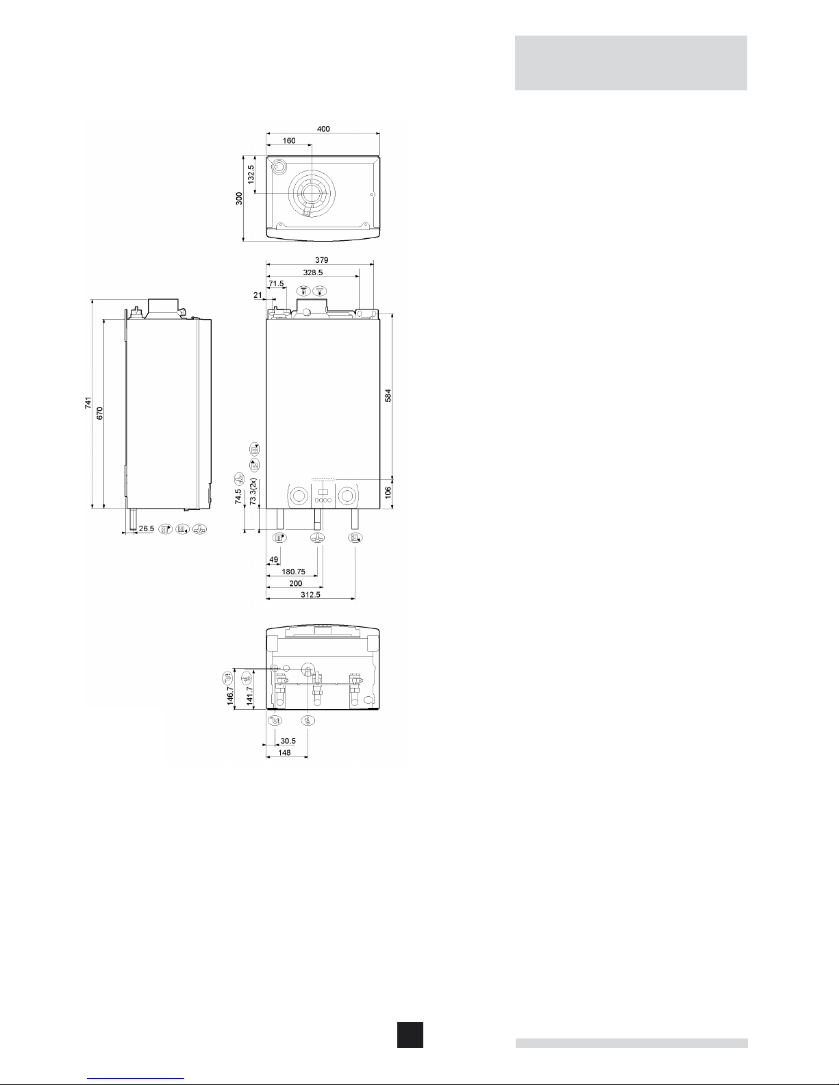
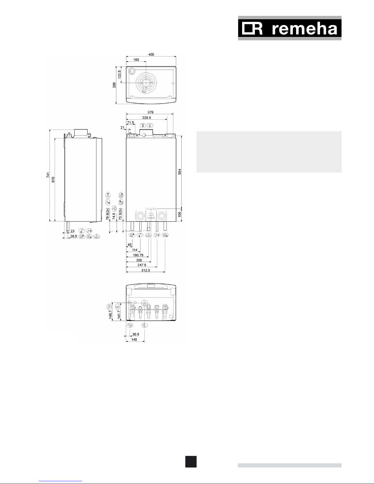
System-type
Return connection Ø 22 mm
Flow connection Ø 22 mm
Gas connection Ø 22 mm
Combustion air inlet Ø 100 mm (concentric)
Flue duct Ø 60 mm (concentric)
Condensate drain connection ¾”
(standard overflow pipe size)
º Connection safety valve Ø 15 mm
2.2.2 Dimensions and connection points.
LT.AL.W7H.000.005
9
Combi-type
Return connection Ø 22 mm
Flow connection Ø 22 mm
Gas connection Ø 22 mm
Combustion air inlet Ø 100 mm (concentric)
Flue duct Ø 60 mm (concentric)
DHW inlet (cold) connection Ø 15 mm
¢ DHW outlet (hot) connection Ø 15 mm
Condensate drain connection ¾”
(standard overflow pipe size)
º Connection safety valve Ø 15 mm
z
• Based on the guidelines and the required installation
space, determine where to mount the Remeha Avanta
Plus.
• In determining the boiler position, consider carefully the
flue outlet position and any pluming consequences.
LT.AL.W7H.000.002
10
Remeha Avanta Plus
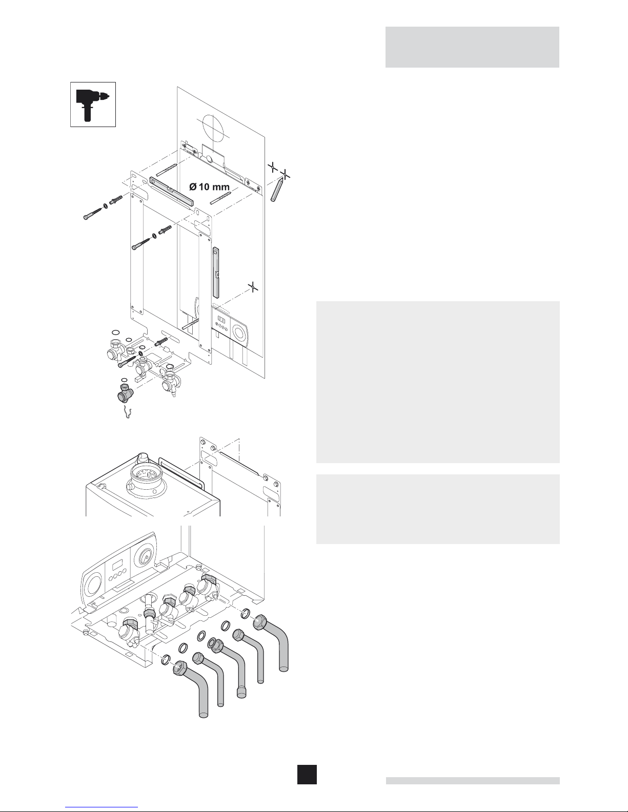
2.2.3 Mounting the Remeha Avanta Plus
LT.AL.W7H.000.012
• Remove the mounting plate and template from the box.
• Using the template determine and mark the position of the
three mounting holes and center line of flue, making sure
the plate is absolutely level.
• Drill the (Ø 10 mm) holes.
• Fit the (Ø 10 mm) plugs.
• Fit (Ø 8 mm) screws into the plugs.
• Check the mounting plate is level and tighten the screws.
• Fit the valve set to the mounting plate.
• Fit fibre washers on the CH valves.
• Remove boiler from the box and suspend it on mounting
plate.
• Connect the valves to the boiler remembering to fit fibre
washers supplied.
• Connect the supplied copper tails to the isolating valves.
m
• The boiler should be mounted on a suitable vertical wall
which is able to support the weight of the boiler.
• The boiler should be mounted in a room which, even during
severe cold weather, remains frost-free.
• If the boiler is to be installed in a timber framed building,
please refer to British Gas publication: ‘Guide for Gas
Installations in Timber frame Housing’, reference DM2.
• In a new installation it is possible to fit just the wall plate and
valve set to enable the system pipework to be completed
and tested before fitting the boiler at a later date (place
fibre washers supplied in a safe place for use when fitting
the boiler).
z
• Make sure the boiler and any open connections are
protected from building etc. dust during the installation.
• There must be a 3 amp fused switched spur within 1m of
the boiler.
• Provision must be made for the condensate discharge.
2.3 Water-side connections
2.3.1 Water flow
An internal automatic flow by-pass is supplied in the Avanta
Plus to ensure correct operation on systems fitted with TRV’s
on all heat emitters. The ‘abc
®
’ control also monitors the temperature difference across the flow and return connections and
the rate of temperature rise and will automatically regulate the
boiler output to ensure that it remains operational for as long
as possible without the need to ‘lock out’ requiring a manual
re-set.
11
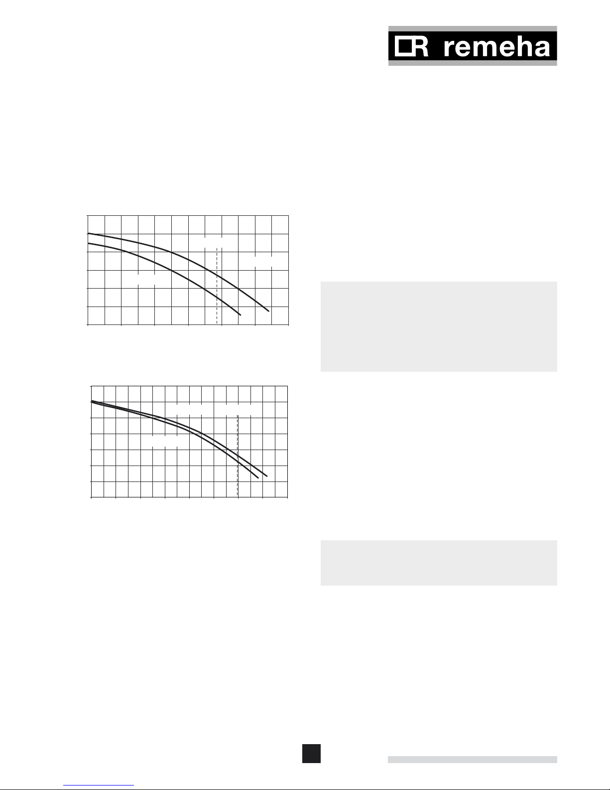
Residual head UPR 15-60
0
100
200
300
400
500
600
0 200 400 600 800 1000 1200
CH-flow [l/h]
Residualhead[mbar]
dT 20°C 18kW
Pump 'high'
Pump 'low'
Residual head UPR 15-70
0
100
200
300
400
500
600
700
0 200 400 600 800 1000 1200 1400 1600
CH- flow [l/h]
Residual head [mbar]
Pump 'high'
Pump 'low'
dT 20°C 28kW
2.3.2 Circulation pumps
The Remeha Avanta Plus 24s and 28c are fitted with the
Grundfos UPR 15-60 and the Avanta Plus 35c and 39c with
the UPR 15-70, two-speed circulation pumps. The control unit
ensures that when the hot-water function is active, the pump
runs at ‘high’. The factory setting of the pump for CH function is ‘low.’ If necessary, the service installer can adjust this
to ‘high’ by switching parameter 21 (from 0 to 1) see par.
2.9.8.
LT.AL.W7H.000.013
LT.AL.W7H.000.014
2.3.3 Additional guidelines for the domestic and CH water
• The system should be filled with mains cold water (for the
UK this will usually have a pH of between 7 and 8).
• Power flush the pipes and radiators thoroughly to remove
all fluxes and debris before connecting the boiler to the central heating system in accordance with BS 7593 (1992).
m
• The temperature of the central heating pipes and the
radiators can rise to 95°C.
• Use untreated tap water only to fill the CH system.
• The pH value of the system water must be between 6 and 9.
• In case inhibitors are being used, please follow the
instructions given in par. 2.3.4.
2.3.4 Water treatment
If used correctly water treatment can improve the boilers
efficiency and increase the anticipated life expectancy of the
boiler. For further information a special document “Quality
requirements CH water” is available from Broag.
As most systems contain a variety of metals, it is considered
good practice to provide some form of water treatment in order
to prevent or reduce the following:
• Metallic corrosion
• Formation of scale and sludge
• Microbiological contamination
• Chemical changes in the untreated system water
m
All scale deposits however small will reduce the efficiency of
the boiler and should be prevented.
Suitable chemicals and their use should be discussed with a
specialist water treatment company prior to carrying out any
work (environmental aspects, health aspects). The specification of the system and manufacturers recommendations must
be taken into account, along with the age and condition of
the system. New systems should be flushed thoroughly to
BS 7593(1992) to remove all traces of flux, debris, grease
and metal swarf generated during installation. Care to be
taken with old systems to ensure any black metallic iron oxide
sludge and other corrosive residues are removed, again by
power flushing, ensuring that the system is drained completely
from all low points.

12
Remeha Avanta Plus
z
Please ensure that the new boiler plant is not in circuit when
the flushing takes place, especially if cleansing chemicals are
used to assist the process.
It is important to check the inhibitor concentration after installation, system modifications, filling the system and every service
in accordance with these instructions.
For the correct dosage and the suitability of inhibitors for use
with our boilers and for further information on water treatment
or system cleaning we advise direct contact with either of the
following companies:
‘Copal
®
’ manufactured by:
Fernox, Cookson Electronics
Forsyth Road
Sheerwater
Woking
Surrey GU21 5RZ
Tel No: 01483 793200
Fax No: 01483 793201
Email: sales@fernox.com
Web site: www.fernox.com
or:
Sentinal ‘X100
®
’ manufactured by:
BetzDearborn Ltd
Sentinal
Foundry Lane
Widnes
Cheshire WA8 8UD
Tel No: 0151 424 5351
Fax No: 0151 420 5447
2.3.5 Safety valve discharge
A pressure relief safety valve is fitted in the boiler set to the
maximum operating pressure of the boiler at 3 bar.
If the pressure in the boiler becomes too high the pressure is
relieved by releasing water outside via the safety valve discharge pipe. The safety valve discharge pipe must be at least
15 mm Ø. The discharge should be terminated facing downwards exterior to the building in a position where discharging
water will not create danger or nuisance but remains in a visible position.
13
2.3.6 Expansion vessel
An 8 litre expansion vessel (with the vessel charge set to 1.0
bar) is fitted as standard within the boiler case and is suitable
for use in a heating system with a water content up to 100
litres, operating at a flow temperature of 80°C, a maximum
pressure of 3 bar and a maximum system static head of 5
metres above the boiler. If the system water content is greater
than 100 litres, or the system static head above the boiler is
greater than 5 m, an additional vessel must be installed in the
system to allow for the increase in expansion, see table 01.
m
Install additional vessel according BS 5449, part1.
Boiler Safety Valve Setting
(Bar) 3.0
Vessel Charge (Bar) 0.5 1 1.5
Heating System Water Content
(Litres)
Expansion Vessel Size
(Litres)
100 4.8 8.0 13.3
125 6.0 10.0 16.6
150 7.2 12.0 20.0
175 8.4 14.0 23.3
200 9.6 16.0 26.6
250 12.0 20.0 33.3
300 14.4 24.0 39.9
For other system volumes,
multiply the system volume
by the factor across:
0.048 0.080 0.133
table 01 Expansion Vessel Size
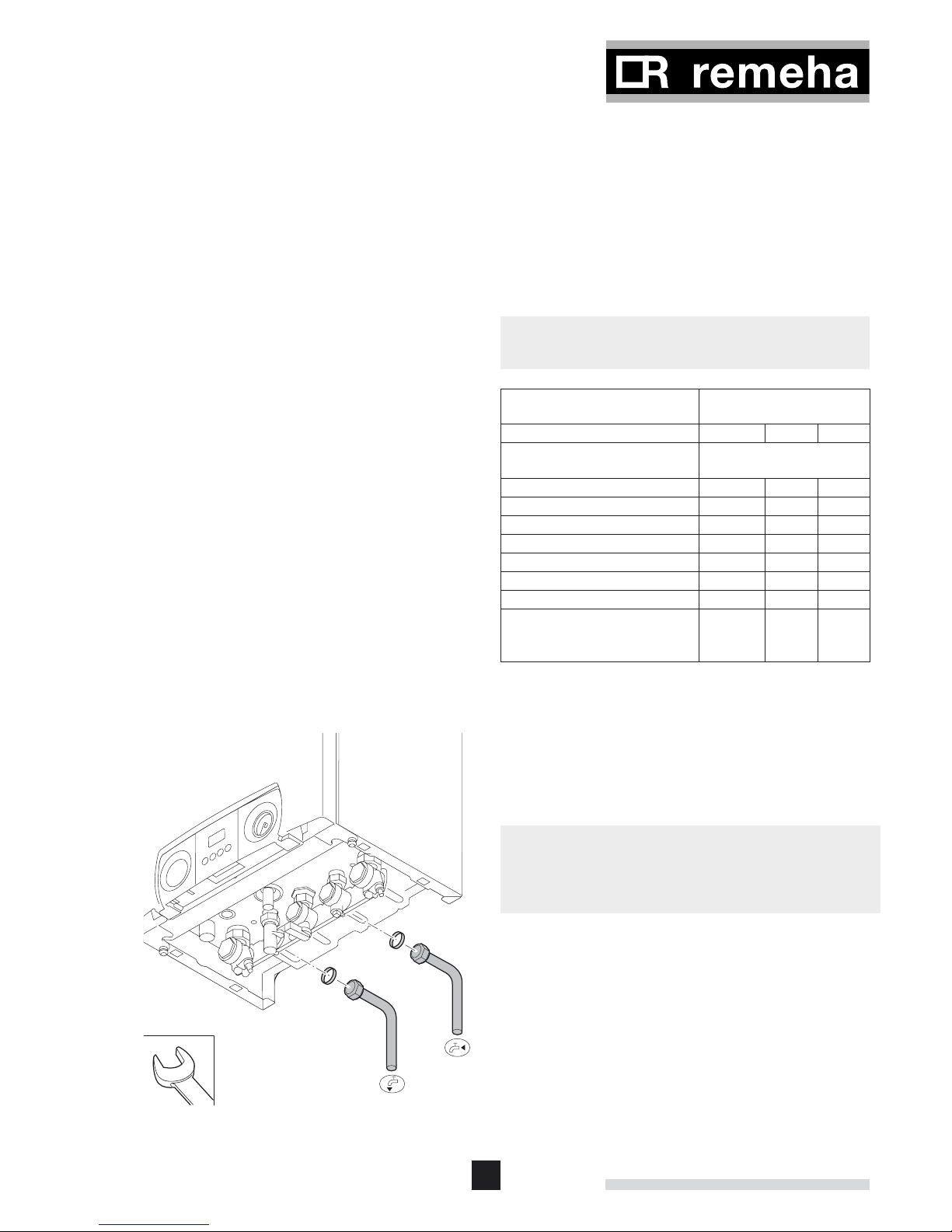
2.3.7 Connecting DHW pipes (Combi-type only)
LT.AL.W7H.000.015
• Fit the outlet pipe for hot water to the DHW outlet ¢ 15 mm
Ø connection.
• Fit the inlet pipe for cold water to the DHW inlet 15 mm
Ø connection.
z
• The DHW pipes must be connected in accordance with
current regulations.
• For plastic pipes, follow the manufacturer’s instructions
(for connection).
14
Remeha Avanta Plus
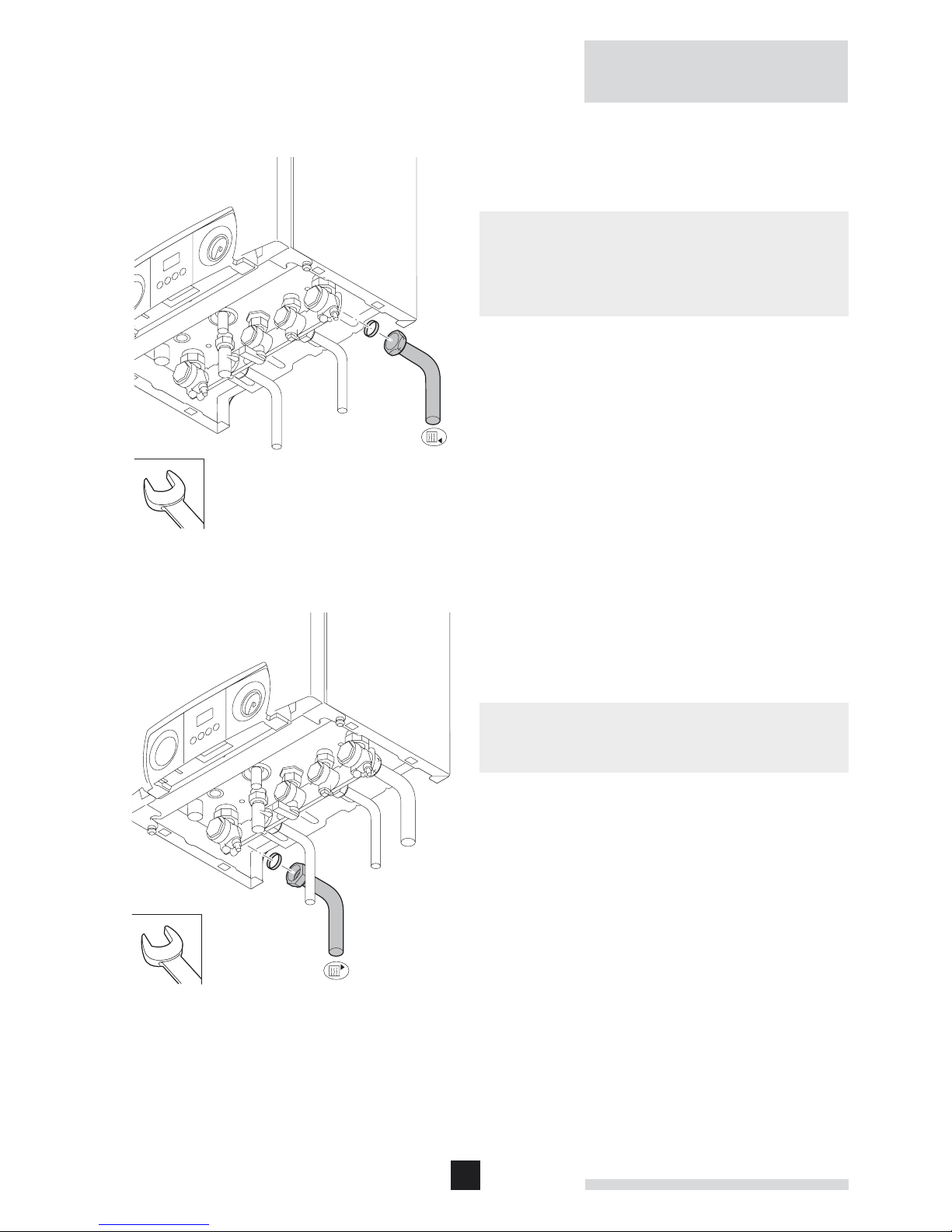
2.3.8 Connecting the ‘CH return’
LT.AL.W7H.000.016
• Fit the inlet pipe for CH water to the ‘CH return’ 22 mm
Ø connection.
o
The Remeha Avanta Plus has a drain cock built into the return
isolating valve
It is considered good practice to install an air separator / dirt
removal device in the return to the boiler.
2.3.9 Connecting ‘CH flow’
LT.AL.W7H.000.017
• Fit the outlet pipe for CH water to the ‘CH flow’ 22 mm
Ø connection.
o
The Remeha Avanta Plus has a drain cock built into the flow
isolating valve.
15
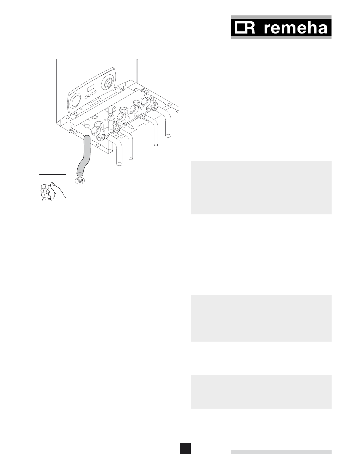
2.3.10 Connecting condensate drain
LT.AL.W7H.000.018
• Connect the condensate drain outlet to a suitable
waste water drain point using acid resisting pipe work
(i.e. - ¾” overflow). To enable the siphon in the boiler to be
removed / serviced, the connection should not be a permanent one (i.e. “push fit” system).
• To prevent the risk of freezing connect the condensate into
an internal vertical soil pipe using a tundish (air break) c/w
a min 75 mm water seal trap.
• If the condensate pipe has to run externally make sure
this is done by realizing the shortest possible route, and
increase the diameter to at least 1¼” or insulate it with
weather resistant insulation.
• The drain should slope at least 3 cm per meter, with a maximum horizontal length of 5 m.
z
• If connecting into an internal discharge branch (i.e. sink
waste etc) the connection must be down stream of the
existing waste trap.
• Fill the boiler siphon with water before operation, to prevent
flue gasses discharging into the room.
• The condensate drain must be connected in accordance
with current regulations.
2.3.11 Connecting under floor heating
The Remeha Avanta Plus can be connected directly to an
under floor heating system.
If plastic pipes have been used they must be made oxygen diffusion proof in compliance with DIN 4726/4729.
When installing under floor heating with a separate pump, the
layout should be such that the under floor heating pump cannot cause a flow to the boiler if there is no heat demand. A low
loss header should therefore be fitted between the system and
the boiler.
z
Please ensure that the residual pump duty of the boiler is
sufficient for the resistance of the under floor system. If not a
low loss header should be used to separate the boiler from
the under floor circuit to allow a separate pump sized for the
resistance of the under floor system to be used.
2.4 Gas-side connections
2.4.1 Additional guidelines for gas connections
m
Before installation, check that the gas meter has sufficient
capacity for the demand. Remember to consider the
consumption of all household appliances.
16
Remeha Avanta Plus
2.4.2 Adjusting boiler to other gas-type
The Avanta Plus boilers are suitable for both natural gas and
propane firing. For the Avanta Plus 39c an optional LPG-set is
needed. The boilers are supplied as standard set for natural
gas (H), therefore the following procedure must be carried out
BEFORE the boilers are fired and commissioned for the first
time on propane: Adjust the fan speed (see Par. 2.9.8) and
adjust the gas/air ratio (see Par. 2.9.3).
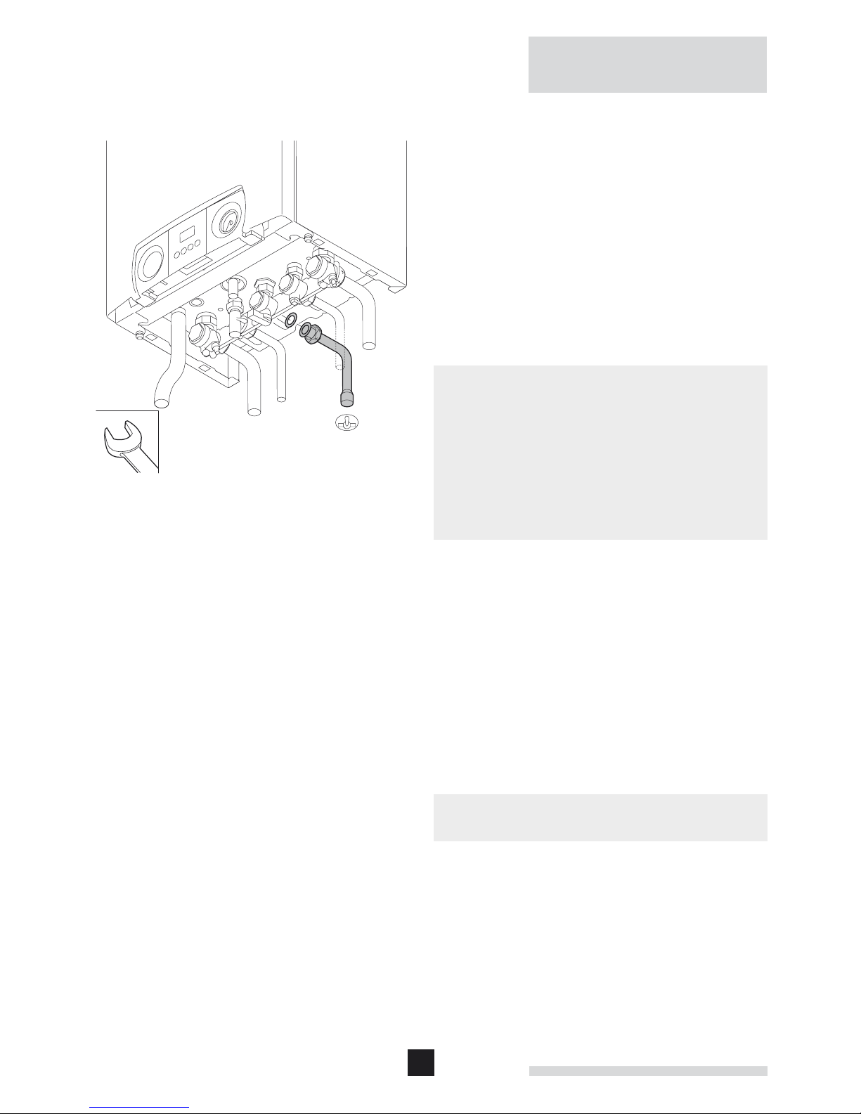
2.4.3 Connecting the gas supply
LT.AL.W7H.000.019
• Before starting any work on the gas supply, turn off the
main isolation valve.
• Connect the gas supply to the 22 mm Ø boiler con-
nection.
m
• Make sure there is no dirt in the gas pipe. Blow through the
pipe before installation or tap well to purge.
• Make sure that the minimum gas service pressure is high
enough (in full load > 17 mbar).
• Preferably install a gas filter in the gas pipe to prevent the
gas block from getting dirty.
• The gas supply must be connected, tested for soundness
and purged by a qualified Engineer and in accordance with
BS6891.
2.5 Flue terminal and air supply connections
The Remeha Avanta Plus is only suitable for room sealed
operation with a standard concentric connection 60/100 mm Ø
or the optional 80/125 mm Ø connection.
Detailed recommendations for air supply and flue terminals are
given in BS 5440.
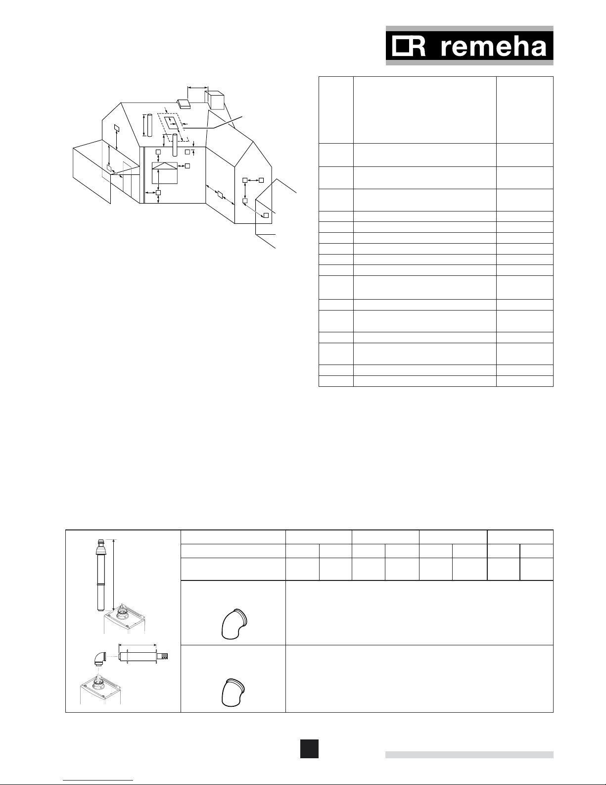
2.5.1 Flue terminal positions
The flue terminal must be located with care to ensure that the
products of combustion are dispersed properly in all weather
conditions and cause minimum nuisance to the building user
or any adjacent buildings. If the terminal is positioned less
than 2 m above the ground, balcony, or flat roof where access
by persons is possible a suitable guard must be employed.
z
The boiler will produce a water vapour plume during normal
operation.
Positions for the Remeha Avanta
Plus are shown in the figure
and table 02.
17
G
G
A
A
B
600 mm
600 mm
2000 mm
D,E
S
S
F
P
H
C
J
J
L
M
K,N
No flue must penetrate
area within dotted lines
round roof light
LT.AL.W7H.000.020
Dimen-
sions
Terminal location Minimum
distance
(in mm)
to terminal
(room
sealed)
A Directly below an opening, air brick,
opening window, etc.
300
B Above an opening, air brick, opening
window, etc.
300
C Horizontally to an opening, air brick,
opening window, etc.
300
D Below a gutter or sanitary pipe work 40
1)
E Below the eaves 40
1)
F Below a balcony or carport roof 40
1)
G Above ground, roof or balcony level 300
H From vertical drain/soil pipe work 40
1)
J From an internal or external corner 40
1)
K From a surface or boundary facing the
terminal
600
2)
L Vertically from a terminal on same wall 1500
M Horizontally from a terminal on same
wall
300
N From a terminal facing the terminal 1200
P From an opening in a carport (e.g.
door, window) into the building
1200
R From a vertical structure on the roof n/a
S Above an intersection with the roof
n/a
table 02 Minimum distances to terminal
1)
= We advise to use deflectors in case of these small dis-
tances.
2)
= Where the terminal is positioned directly opposite an
opening in the facing wall the min will be 2 m.
n/a = not applicable.
2.5.2 Room sealed flue
See table 03 for the maximum pipe length of flue ducts and air
supply pipes for this ‘room sealed’ application.
It is not necessary to provide combustion air to the room or
internal space in which the boiler is installed.
24s 28c 35c 39c
Diameter in mm Ø
60/100 80/125 60/100 80/125 60/100 80/125 60/100 80/125
Maximum length ‘L’
allowed [m]
6 29 6 29 7 30 5 25
Eq. Length of 90° elbow 1.4
Eq. Length of 45° elbow 0.65
L
VRS roof
mounted
room sealed
terminal
L
80/125 or 60/100
table 03 Maximum pipe lengths for fl ue duct and air supply in
room sealed application
18
Remeha Avanta Plus
158 mm
ø 125 mm
2
1
2
1
z
For flue installations not covered by this booklet, please
contact our technical help line 0118 978 3434.
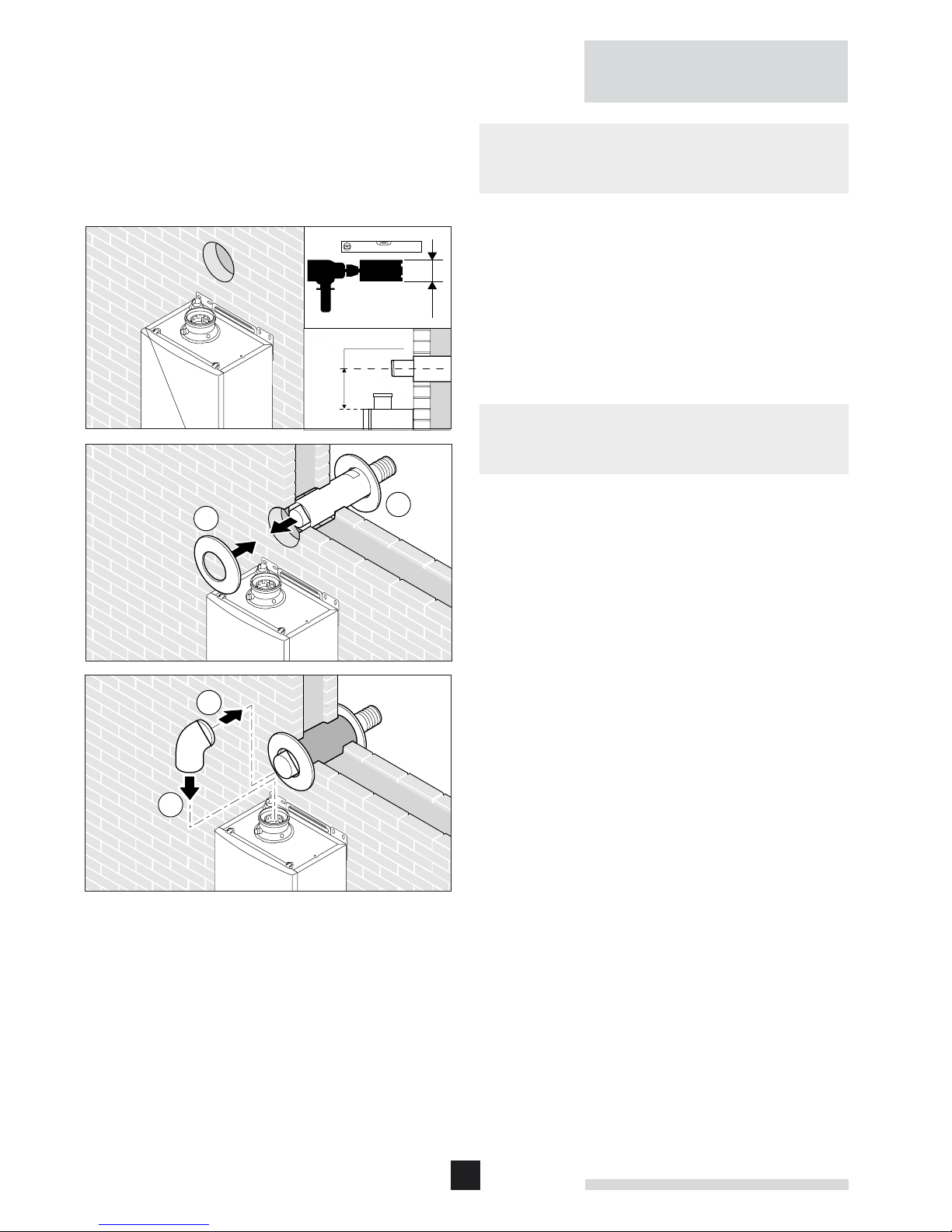
2.5.3 Connecting the flue terminal and air supply
LT.AL.W7H.000.021
• Check the depth of the wall and cut the terminal to suit
– taking note of the cutting instructions supplied with it
• Core drill a 125 mm Ø hole in the wall, fit the rubber closure
plate at the exit end and slide the terminal through the wall
until the closure plate is clear of the outer edge of the wall
– pull back the terminal till the closure plate is flush then fit
inner wall closure to secure.
z
• All connections must be airtight and waterproof.
• Horizontal extension sections should slope towards the
boiler (at least 3 cm per metre).
19
230 V
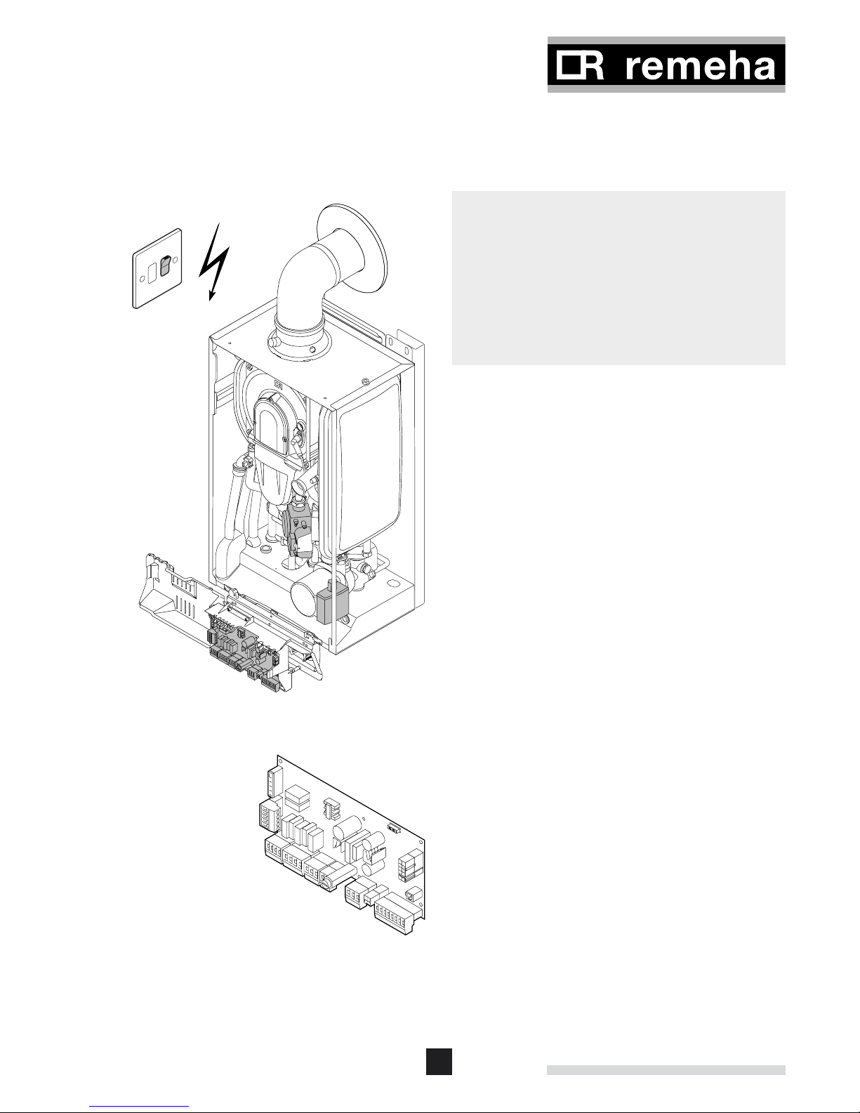
2.6 Electrical connection
• Connect the boiler to the fused (3 amp) switch spur unit
adjacent to boiler.
• The switch unit must always be accessible.
LT.AL.W7H.000.022
{
When the switch spur is on the following components of this
appliance can be live (230 V):
• electrical connection pump;
• electrical connection gas combination block;
• electrical connection three-way valve;
• most parts of the control unit;
• ignition transformer;
• X1, X2, X4, X5, X6 and X7 terminal strip;
• 230 V supply cable connection.
2.6.1 The control unit
The Remeha Avanta Plus has an electronic regulation and
control unit with an integrated ionisation flame detector. The
heart of the boiler control unit is a microprocessor, the ‘abc
®’
,
which controls and protects the boiler.
LT.AL.W7H.000.023
The boiler is not phase sensitive. The maximum rated input is
between 115 and 180 W (depending on boiler type).
The boiler is fully pre-wired internally, all external connections
can be made using the terminal strips X5 - X7 - X9 and 230
V input (X2 terminal). See the diagram for the position of the
connectors and fuse (F2) on the control unit.
The most important properties of the control unit are summarized in table 04.
20
Remeha Avanta Plus
1
2
Manufacturer Sit Controls
Supply voltage 230 V – 1ph – 50 Hz
Pre-purge time 3 s
Post-purge time 5 s
Ignition time 2.5 s
Safety time 5 s
Anti-cycling time 3 till 10 min.
Fuse value F1 (230 V) 2 AT
DC fan (for 24s, 35c and 28c) 24 VDC
AC fan (for 39c only) 230 VAC
table 04 Control unit characteristics
m
Any loads other than those specified above are only allowed if
an isolating transformer is used.
The output of the Remeha Avanta Plus can be controlled in
the following ways:
On/off control – volt free switching - The boilers internal
control will modulate the output to achieve the flow temperature set point of the boiler. This contact is on the X9 terminal
strip (low voltage only).
Modulated control – Open Therm - The external controls will
modulate the boiler’s output to achieve the flow temperature
determined by the modulating regulator. This contact is on the
X9 terminal strip (low voltage only).
On/off control – 230 V switching - The boilers internal control will modulate the output to achieve the flow temperature
set point of the boiler. This contact is on the X2 terminal strip
(230 VAC only).
Modulated control – Open Therm in combination with an
externally mounted simple 230 V switching time clock -
The boiler will provide room compensated heating and time
control over CH and DHW (System boiler).
z
• All connections on terminal X1, X2, X4, X5, X6 and X7 are
230 VAC.
• All connections on terminal X9 are low voltage only.
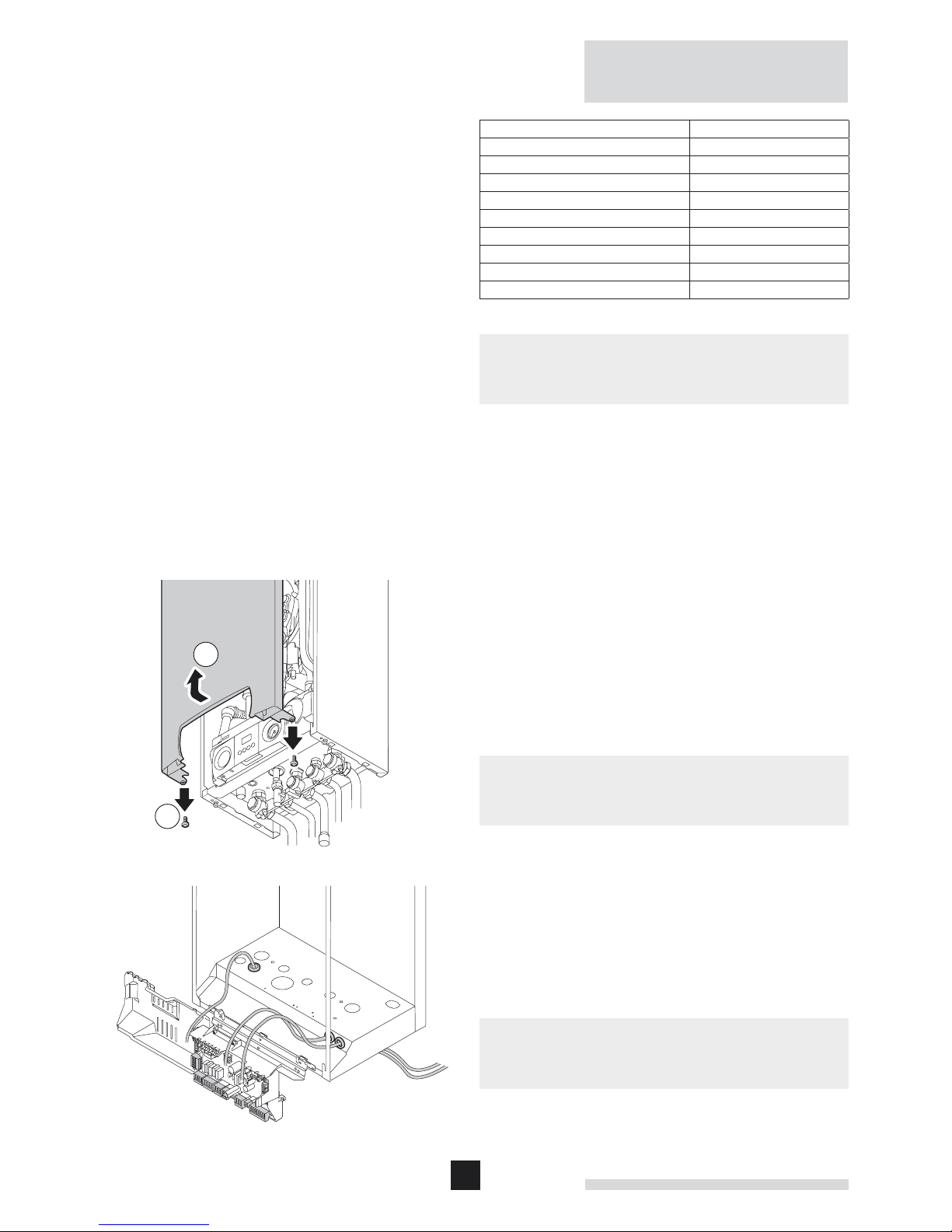
2.7 Connecting external controls
• Release the two screws at the bottom of the front casing
and remove the front casing.
• Feed the cables through the grommet in the base of the
boiler.
• Connect the cables to the relevant connectors, as shown in
the diagrams.
LT.AL.W7H.000.024
{
• Isolate power supply at the fused spur before carrying out
any work on the boiler controls.
21
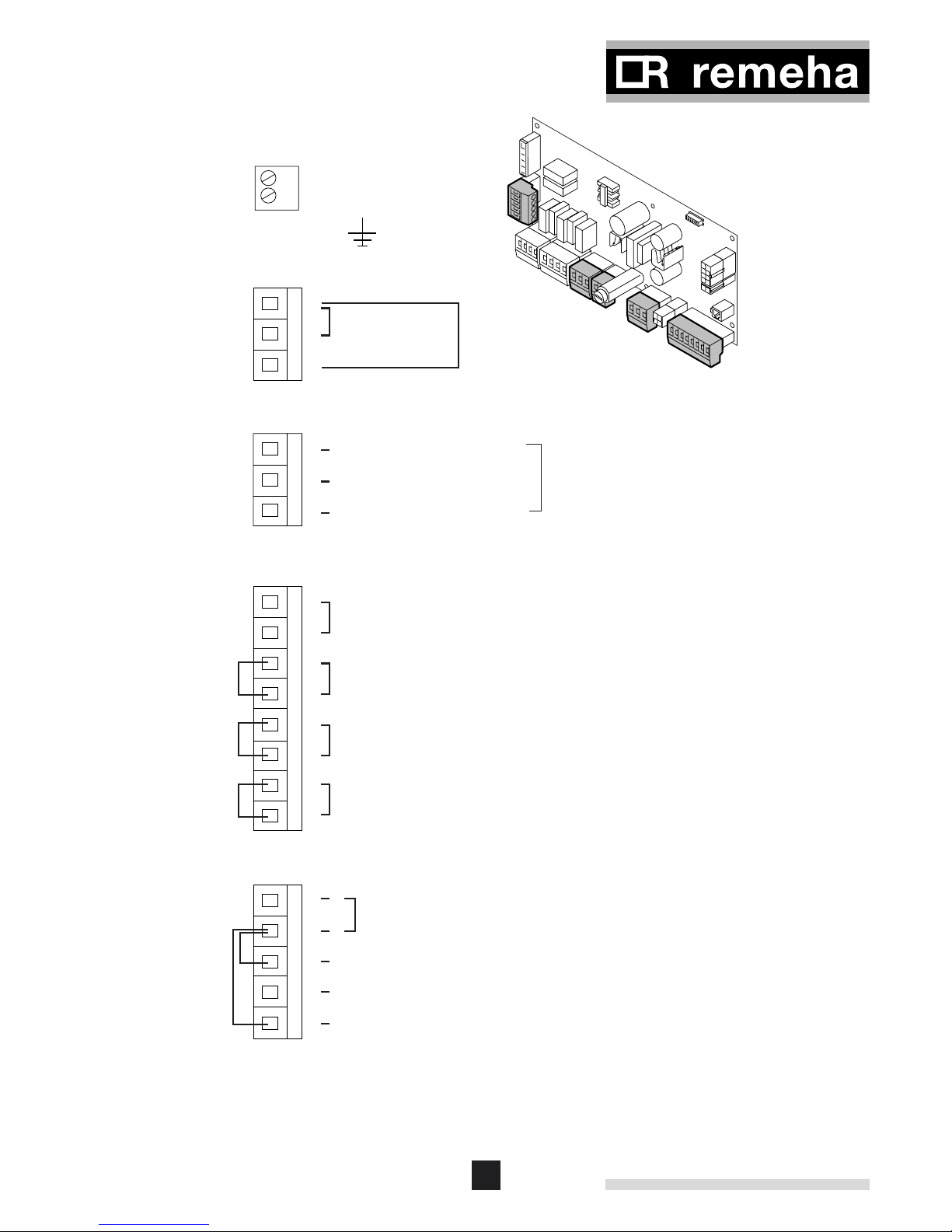
L
N
230v - 3 Amp
Power Supply
Terminal
Block X5
X2
X5
X6
X7
X9
Terminal
Block X9
Exist
links
Exist
links
Terminal
Block X2
1
Neutral
2
Open valve to DHW (230v)
3
Open valve to HTG (230v)
Outside sensor (red band) for direct boiler weather compensation
or when used in conjuction with a compatable Open Therm
control eg: Chronotherm or Celcia 20
DHW sensor (red band) or volt free thermostat (make on temp fall)
Remove existing link to use this function
External interlock (volt free)
Remove existing link to use function
Modulating - using Open Therm control
eg: Honeywell Chronotherm or Celcia 20
On / Off - using volt free switching control
eg: Celcia 10 or low volt room thermostat
Power supply to external time clock -230v
Switch live (230v) from external time clock DHW demand
Remove existing link 4-3 to use this function
Switch live (230v) from external time clock HTG demand
Remove existing link 4-1 to use this function
NOTE: Terminal blocks are not in line as shown - diagramatic only
For external DHW priority
diverting valve on System boiler
when used in conjunction with
"Open Therm" compensation
Terminal
Block X7
Terminal
Block X6
1
2
Common Alarm
(Closes on alarm)
Boiler Run
(Closes on run)
3
1
2
3
4
5
6
7
8
5
4NL
3
2
1
E
LT.AL.W7H.000.025
22
Remeha Avanta Plus
X9
Terminal
Block X9
Modulating - using Open Therm control
eg: Honeywell Chronotherm or Celcia 20
On / Off - using simple volt free switching control
1
2
3
4
5
6
7
8
Exist
links
X2
Exist
links
Terminal
Block X2
Power supply to external time clock -230v
Switch live (230v) from external time clock DHW demand
Remove existing link 4-3 to use this function
Switch live (230v) from external time clock HTG demand
Remove existing link 4-1 to use this function
5
4NL
3
2
1
2.7.1 On/off control – room temperature (volt free
switching)
LT.AL.W7H.000.026
The Remeha Avanta Plus can be connected to a 2-wire on/off
thermostat, such as the Remeha Celcia 10.
Mount the thermostat in a reference room (usually the living
room).
• Remove existing link between connectors 7 and 8 of the X9
terminal strip before use;
• Connect the 2-wire 24 V room thermostat to connectors 7
and 8 of the X9 terminal strip.
z
If a room thermostat with an anticipation resistor is being used,
parameter p5 should be changed from 0 to 1, see par. 2.9.8.
2.7.2 Time control using an internal or external 230 V
clock
{
When the switch spur is on, the terminal strip X2 will be live
(230 V).
LT.AL.W7H.000.027
• A 230 V two channel time clock for CH and DHW control
can be connected to the Remeha Avanta Plus
.
Live 230 V supply for the time clock - connect to connectors
4 (N) and 5 (L) on X2 terminal strip.
• For CH - remove existing link between connectors 4 and 1
of the X2 terminal strip and connect the 230 V output from
the time clock to terminal 1 on the terminal strip X2.
• For DHW - remove existing link between connectors 4 and
3 of the X2 terminal strip and connect the 230 V output from
the time clock to terminal 3 on the terminal strip X2.
m
For this option to function correctly a link or room control must
be fitted between connectors 7 and 8 of X9 terminal strip
(Remove existing link before use).
23
X9
Terminal
Block X9
Modulating - using Open Therm control
eg: Honeywell Chronotherm or Celcia 20
On / Off - using simple volt free switching control
1
2
3
4
5
6
7
8
Exist
links
LT.AL.W7H.000.028
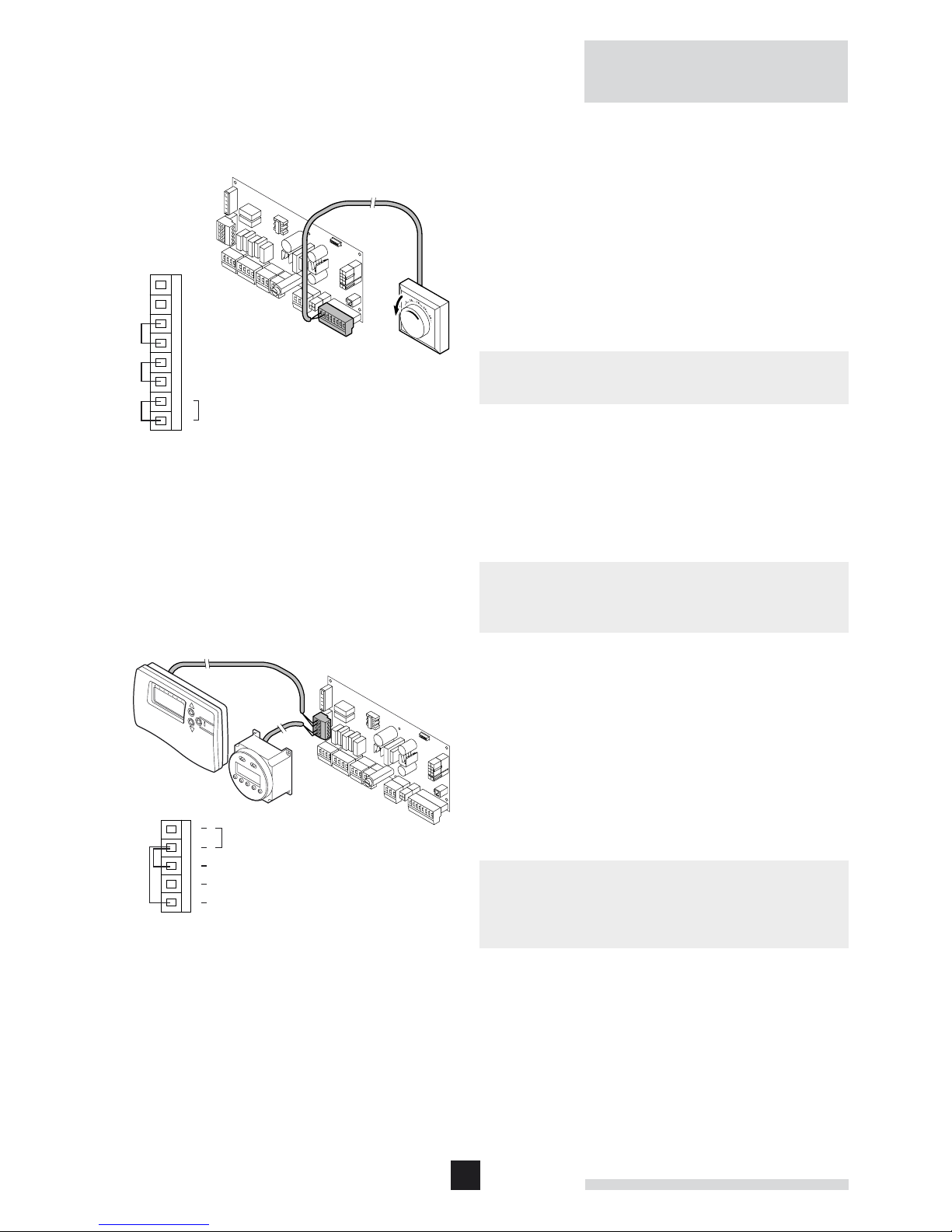
2.7.4 Modulating control – room or outside compensation
2.7.3 Connecting a 230 V time clock in combination with
a modulating room control
With an externally mounted simple 230 V switching time clock
connected to connectors on X2 terminal strip and a Celcia 15
connected to connectors 7 and 8 of X9 terminal strip (remove
existing link between connectors 7 and 8 before use), the
Remeha Avanta Plus will provide room compensated heating
and time control over CH and DHW (System boiler).
o
An OpenTherm® room modulating control (Celcia 15) used in
conjunction with a simple external 230 V time clock will
provide easy to set up and operate - timed room compensation heating
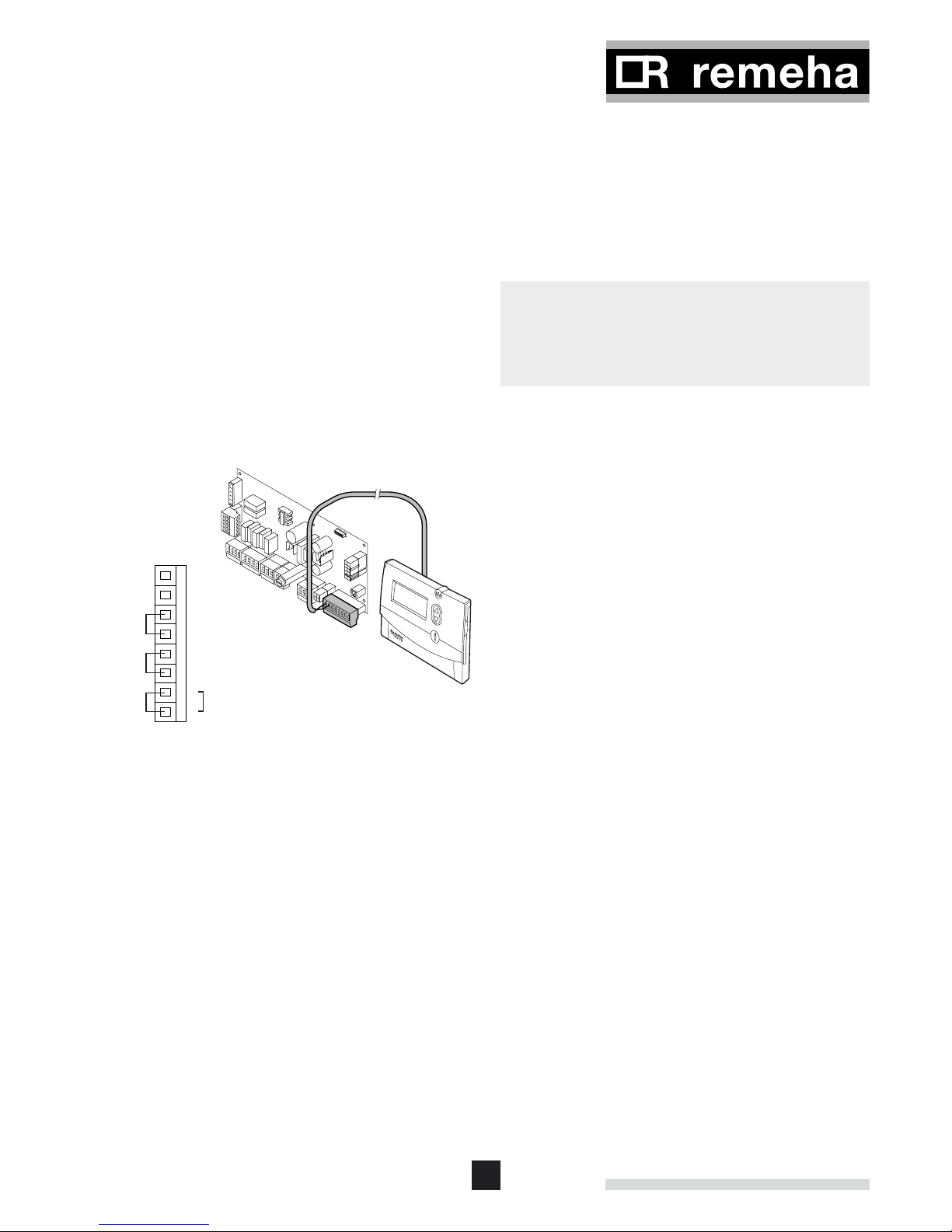
The Remeha Avanta Plus has an OpenTherm
®
interface. This
enables our modulating range of OpenTherm
®
room controls
(e.g. the Remeha Celcia 15 or 20) to be connected without
any further modifications.
• Mount the control in a reference room (usually the living
room).
• Connect the two-wire interface cables to connectors 7 and
8 of the X9 terminal strip (remove existing link between
connectors 7 and 8 before use).
• When using the Celcia 20 it is possible to add the outside
sensor to provide weather compensation with room adjustment. Connect the outside sensor to connectors 1 and 2 of
the X9 terminal strip.

24
Remeha Avanta Plus
X9
Terminal
Block X9
Outside sensor (red band) for direct boiler weather compensation
or when used in conjuction with a compatable Open Therm
control eg: Chronotherm or Celcia 20
1
2
3
4
5
6
7
8
Exist
links
20
40
60
75
01020-15
Factory setting
If the DHW water temperature on the OpenTherm® control can
be adjusted, then the Remeha Avanta Plus will supply water at
the temperature determined at the OpenTherm
®
with the maximum being set in the boiler.
OpenTherm
®
is an industry standard modulating control avail-
able from several control manufacturers.
z
The Remeha Avanta Plus can therefore be controlled directly
by any other controls with this OpenTherm® logo
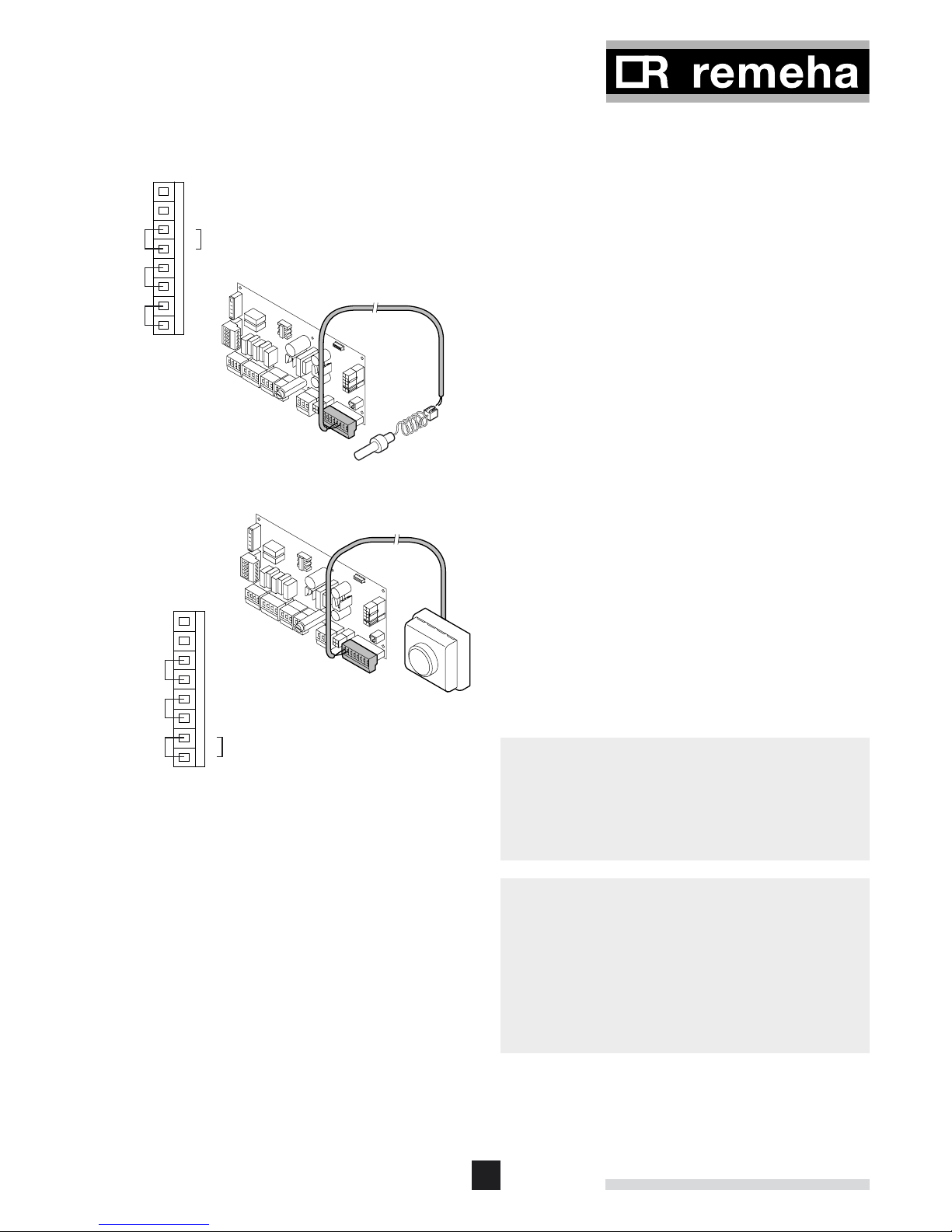
2.7.5 Connecting an outside temperature sensor
LT.AL.W7H.000.029
An outside temperature sensor can be connected to connectors 1 and 2 of the X9 terminal strip.
The boiler will regulate the output using the set point of the
internal heat curve.
This can be set as follows:
- Outside temperature minimum set point = -15°C (adjustable
with parameter p29 to between 0 and -30°C)
- Outside temperature maximum set point = 20°C (adjustable
with parameter p28 to between 0 and 40°C)
- Flow temperature set point at maximum outside tempera-
ture = 20°C (adjustable with parameter p27 to between
0 and 60°C)
- Flow temperature set point at minimum outside temperature
= 20°C (adjustable with parameter p1 to between
20 and 85°C)
LT.AL.W7H.000.030
o
An outside sensor used in conjunction with a simple 230 V
time clock will provide easy to set up and operate - timed
weather compensation heating based on the above graph.
25
X9
Terminal
Block X9
DHW sensor (red band) or volt free thermostat (make on temp fall)
Remove existing link to use this function
1
2
3
4
5
6
7
8
Exist
links
X9
Terminal
Block X9
Modulating - using Open Therm control
eg: Honeywell Chronotherm or Celcia 20
On / Off - using simple volt free switching control
1
2
3
4
5
6
7
8
Exist
links
2.7.6 Connecting the DHW sensor/thermostat
LT.AL.W7H.000.031
• If an external DHW calorifier is being used with the Avanta
Plus system boiler a volt-free DHW control sensor or thermostat can be connected to connectors 3 and 4 of the X9
terminal strip after removing the existing link. The control
will automatically detect whether a sensor or a thermostat
has been connected.
2.7.7 Connecting a frost thermostat
The boiler must be installed in a frost-free area to prevent the
condensate drain from freezing. However if the temperature of
the CH water in the boiler drops too low, the integrated boiler
protection device is activated as follows:
- at a water temperature below 7°C: the circulation pump is
switched on;
- at a water temperature below 3°C: the boiler is switched on;
- when the water temperature is above 10°C: the boiler is
switched off and the circulation pump runs for another 15
minutes.
o
• A frost thermostat should preferably be installed in rooms
with a high frost risk.
• Connect the frost thermostat in parallel to the room thermo
stat - connectors 7 and 8 of the X9 terminal strip (remove
existing link between connectors 7 and 8 before use).
m
• This function is a protection device for the boiler only, not
for the system or building fabric.
• If a frost thermostat or a modulating room control,
connected across connectors 7 and 8 is activated, the
boiler will operate continuously to achieve the flow set point.
• If the Celcia 20 control has been fitted, with an outside
sensor the boiler and building fabric will be protected.
See the installation documentation supplied with the control.
26
Remeha Avanta Plus
X9
Terminal
Block X9
External interlock (volt free)
Remove existing link to use this function
1
2
3
4
5
6
7
8
Exist
links
X7
Terminal
Block X7
1
2
Common Alarm
(Closes on alarm)
Boiler Run
(Closes on run)
3
X10
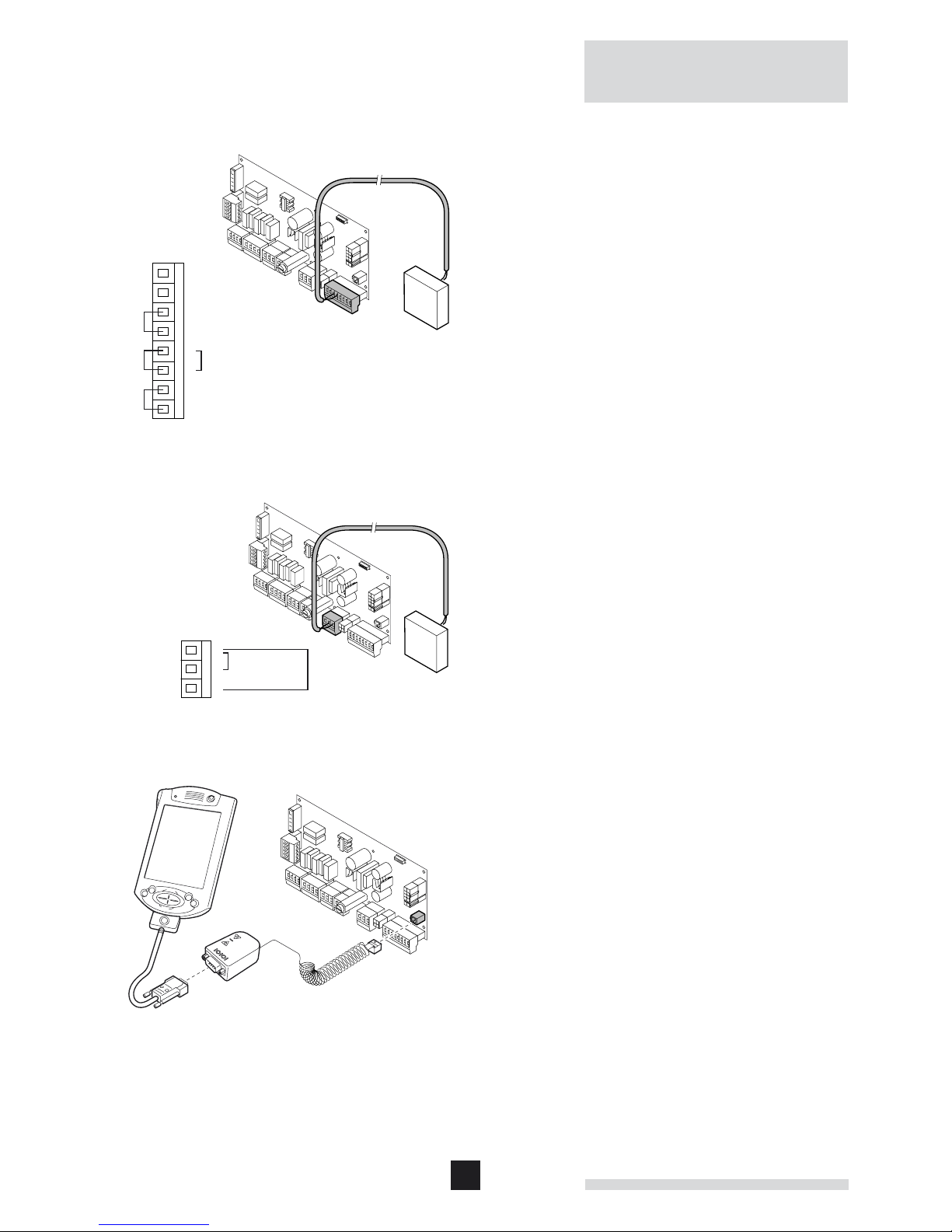
2.7.8 Connecting an external interlock
LT.AL.W7H.000.033
The Remeha Avanta Plus is supplied with an external interlock
function. A volt free switching device (i.e. external gas pressure switch, safety thermostat for under floor heating) can be
connected to connectors 5 and 6 of the X9 terminal strip after
removing the existing link. When this circuit is open the boiler
will shut down with the display showing (code 9) and will
restart when the circuit is closed.
LT.AL.W7H.000.034
2.7.10 Connecting a PC/PDA
LT.AL.W7H.000.035
Using the optional Recom interface package a PC or PDA can
be connected to the X10 “telephone connector”. Using the
Recom PDA service software you can load, change and download various boiler settings and readings. See the user instructions supplied with the software/hardware.
2.7.9 Connecting remote alarm and boiler run indication
As standard the boiler is supplied with 3 volt free connectors
on terminal X7. They can be used for an external gas valve,
remote alarm and boiler run indication.
• Common alarm signal connect to connectors 1 and 2 on
terminal X7. Contact closes on lock out. For this purpose
set parameter 24 from 0 to 1.
• Boiler run signal connect to connectors 1 and 3 on terminal
X7. Contact closes on heat demand. For this purpose set
parameter 24 from 0 to 2.
• Connect an external gas valve to connectors 1 and 3 on
terminal X7. Contact closes when the gas valve is activated. For this purpose set parameter 24 from 0 to 3.
27
X13
X15
X1
X9
X6
X5
X4
X3
X8
X7
X10
X0
X2
X6X0
L N
X1
4 5 1 3 2X21 2 3 4 5X31 2 3 4X41 2 3 4
X8
1 2 3 4X91 2 3 4 5 6 7 8
X13
4 1 3 7 5 6 8
X15X5
1 2 3
1 2
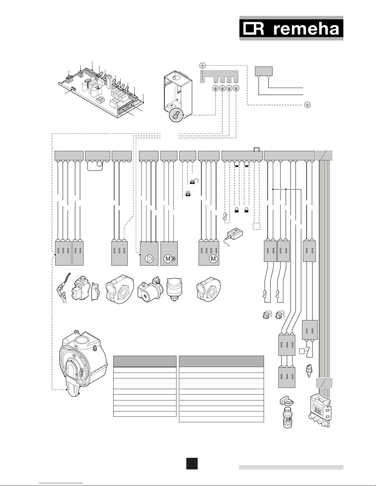
Power supply
230V, 50Hz
L
123
GCV FAN*
*Only for
39c boiler
BP
X31 X81X21X22
15
N
BR
GN/YW
GN/YW
BKBRBL
WH
GY
BR
BK
WH
BK
RD
WH
COMM.
NC.
NO.
BL
WH
GN
RDWHBL
WH
BK
BK
OR
GN
WH
YW
Blocking up entry
Blocking up entry
Compensator / Open Therm
TOs
BR
BR
BL
BL
X7
1 2 3 1 10
1 10
123
DV
1542
FAN
HLT
RsAs
12 12 12
12
T
X134 X133 X131
Fs
123
X132
123
X132A
X131A
BK BLACK
BL BLUE
BR BROWN
GN GREEN
GN/YW GREEN/YELLOW
GY GRAY
RD RED
WH WHITE
YW YELLOW
WIRE COLOURS
As Flow sensor
BP Boiler pump
Fs Flow switch
CP Circulation pump
DV 3-way valve
GCV Gas combination valve
HLT High limit thermostat
Os Outdoor sensor
Rs Return sensor
- - - - Will not be supplied or wired.
BOILER COMPONENTS
*
2.8 Wiring diagram
LT.AL.W7H.000.234
* Remove existing link between connectors 7 and 8 before use
28
Remeha Avanta Plus
1
2345
2.9 Commissioning
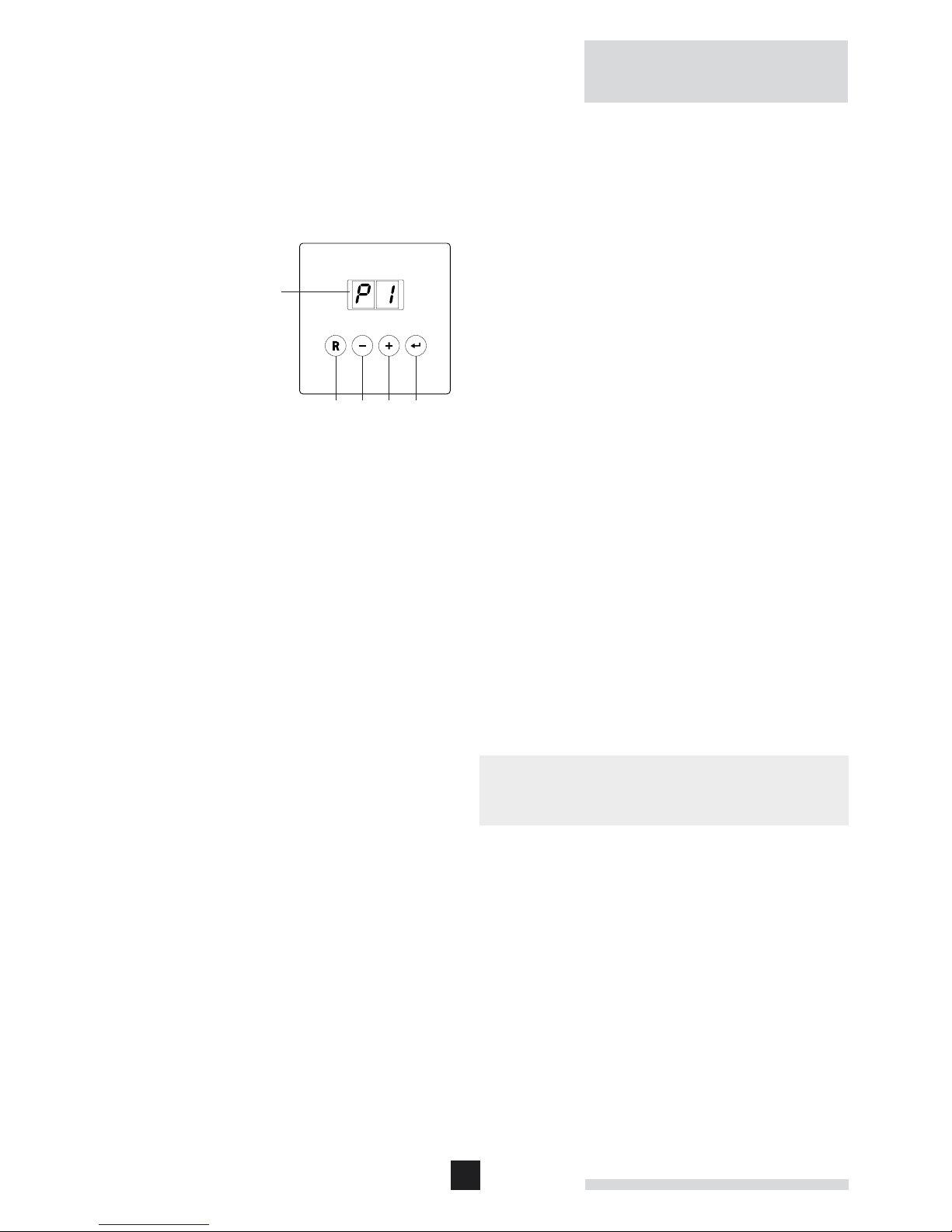
2.9.1 Control Panel
The control panel of the Remeha Avanta Plus has 4 function
keys and a LED display. The function keys are used to read
or change the settings and temperatures.
LT.AL.W7H.000.036
1 = display
2 = [reset] key
3 = [-] key
4 = [+] key
5 = [enter] key
The display has two positions and displays information on the
current operating status of the boiler and any errors. Numbers,
dots and/or letters can appear in the display. The symbols
above the function keys indicate what the function of that particular key then is.
If no key is pressed for longer than three minutes with the
“boiler in stand-by mode”, only one dot is lit. With the “boiler
operating”, two dots are displayed.
• Press any key and the current boiler status and operation
code will appear in the display.
• In the event of a fault, the fault code is displayed instead of
the dots.
2.9.2 Additional guidelines for commissioning
• When commissioning, use the Boiler Log Book.
• Work through all the stages of this section, complete the
commissioning details in the supplied Boiler Log Book and
send a copy of the completed documents to Broag to register the boiler.
• The boiler is supplied as standard for use with Natural Gas
and tested at an operating pressure of 20 mbar.
m
The boiler must not be put into operation with a different type
of gas without reference to Broag.
2.9.3 Putting the boiler into operation
This section details the procedure for putting the boiler into
operation. There are 7 stages to the procedure:
1. Isolating the power supply and opening the front cover;
2. Checking the connections and making the boiler operational;
3. Switching the boiler on and setting the controls;
4. Checking/setting the gas/air ratio at full load;
5. Checking/setting the gas/air ratio at low load;
6. Making the boiler ready for use;
7. Instructing the user.
29
1
2
230 V
Check
1,2 bar
1
2
3
4
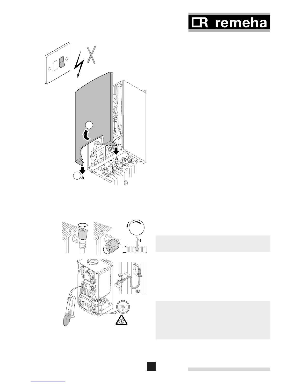
1. Isolating the power supply and opening the front cover
LT.AL.W7H.000.037
• Switch off the boiler at the fused spur and remove the fuse;
• Remove the front panel (release the two screws at the bot-
tom of the front panel, pull the bottom of the panel; forward
and lift off the two pins on the top of the main casing).
2. Checking the connections and making the boiler
operational
z
Open the valves on all the radiators connected to the central
heating system before filling the system with water.
LT.AL.W7H.000.038
• Open the valves on all the radiators connected to the
central heating system;
• Fill the system with water to the design operating pressure
(normal for a one/two storey house 1.2 bar, minimum
pressure 1 bar, maximum pressure 2.5 bar);
• Whilst filling, air from the system will escape through the
automatic air vents and the pump.
m
• When the vent caps start leaking water, close them with
the vents caps supplied.
• Avoid water getting into the boiler.
• Check the condensate siphon. This should be filled to the
mark with clean water if necessary.
30
Remeha Avanta Plus
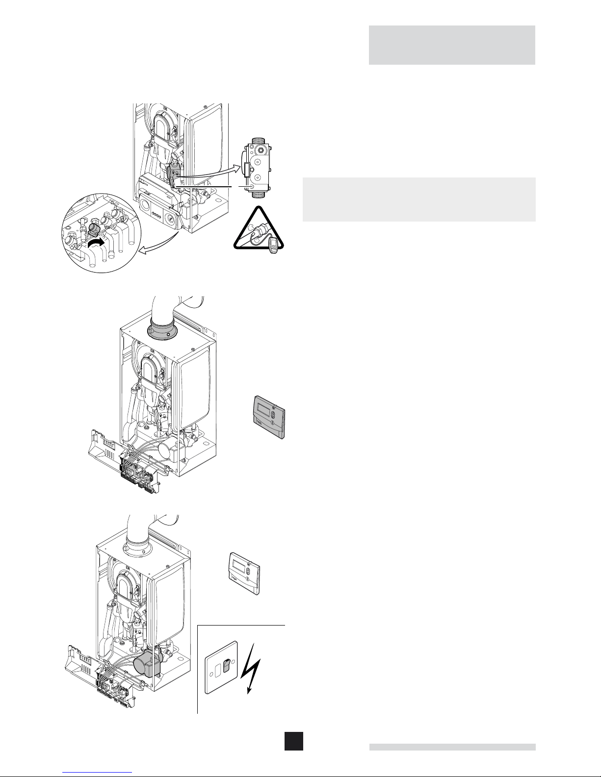
230 V
Check
C
• Check the integral boiler pump – remove chrome centre
screw to vent pump and spin the shaft to check that the
impellor can move freely;
• Check that all boiler connections are watertight;
LT.AL.W7H.000.039
• Open the boiler gas valve and check the static pressure to
the boiler at the measurement point (C) on the gas block.
m
The boiler has been factory tested for natural gas at 20 mbar.
The minimum gas inlet pressure is 17 mbar for natural gas.
• Check that the gas supply to the boiler is gas tight (in
compliance with the current regulations, see Chapter 7 the
maximum test pressure at the gas pipe inlet, with the boiler
gas valve open, is 60 mbar.
• Vent the gas pipe by unscrewing the measurement point
(C) on the gas block (tighten it again as soon as the pipe is
fully vented).
• Check that the gas connections in the boiler are sealed.
• Check that all electrical connections, including the earth
connection, have been made correctly.
• Check the electrical connections to the thermostat and
other external controls.
• Check that the flue-gas and air-supply connections are
sealed.
LT.AL.W7H.000.040
3. Switching the boiler on and setting the controls
LT.AL.W7H.000.041
• Replace the fuse in the spur and switch on the 230 V
power supply.
• Set the controls to heat demand.
• The boiler will begin an automatic venting-programme
(which lasts approx. 3 minutes) and will do this every time
the power supply is isolated.
• The boiler now starts to run. The operational status is
shown in the display. The normal operating status finally
shows 0 in the display.
 Loading...