

REMEHA 610 ECO Technical Information
1
• High efficiency condensing
boiler with low NOX emission
• Heat outputs: 87 - 1146 kW
R e m e h a G a s 6 1 0 E C O
Technical information
Remeha Gas 610 ECO

Remeha Gas 610 ECO
2
3
CONTENTS
Preface 4
1 Safety instructions 5
1.1 Symbols 5
2 General description of boiler 6
3 Design 7
3.1 Boiler version 7
3.2 Operating principle 8
4 Technical data 9
4.1 Dimensions 9
4.2 Technical data 10
4.3 Quotation specification 11
4.4 Delivery options 11
4.5 Accessories 12
5 Efficiency information 13
5.1 Annual efficiency (92/42EEC) 13
5.2 Heat to water efficiency (92/42EEC) 13
5.3 Standing losses 13
6 Application data 13
7 Installation instructions for heating installer 14
7.1 General 14
7.2 Delivery and installation 14
7.3 Flue gas discharge and air supply 16
7.3.1 General 16
7.3.2 Classification due to discharging
flue gases 16
7.3.3 Connection options 16
7.3.4 Inlets/Outlets 16
7.3.5 Other requirements 16
7.3.6 Single boiler conventional flue 17
7.3.7 Single boiler, room sealed flue 17
7.3.8 Different pressure zones 18
7.3.9 Header flue systems 18
7.4 Installation details 18
7.4.1 Water pressure 18
7.4.2 Condensate discharge 18
7.4.3 Water treatment 18
7.4.4 Safety valve 19
7.4.5 Water circulation 19
7.4.6 Thermostat pocket 19
7.4.7 Noise production 20
7.5 Multiple boiler installation 20
8 Installation instructions for electrical
installer 22
8.1 General 22
8.2 Electrical specifications 22
8.2.1 Mains voltage 22
8.2.2 Control unit 22
8.2.3 Power consumption 22
8.2.4 Fuse ratings 22
8.2.5 Temperature control 23
8.2.6 Low water level protection
(flow and content) 23
8.2.7 High limit protection 23
8.2.8 Air pressure differential sensor
(LDS) 24
8.3 Connections 24
8.4 Wiring diagram per module 25
8.5 Switch sequence diagram 26
8.6 Boiler control 26
8.6.1 Introduction 26
8.6.2 Modulating controls general
(two wire control) 26
8.6.3 BMS Analog control
(0-10 Volt DC) 27
8.6.4 2-stage control (high/ low)
(2 x no volt switched pair) 27
8.6.5 4-stage control (4 x no volt
switched pairs) 27
8.7 Other inputs 28
8.7.1 Shut down input 28
8.7.2 Lock-out input 28
8.7.3 External interlock 28
8.7.4 Other outputs 28
8.7.5 Analog output 28
8.7.6 Operation signal 28
8.7.7 Common alarm (lock-out) 28
8.7.8 External gas valve control 28
8.8 Options/ accessories 28
8.8.1 System pressure sensor 28
8.8.2 Gas valve leak proving system
(VPS) 29
8.8.3 Minimum gas pressure switch 29
8.8.4 Return butterfly valve
(not Broag supply) 29
8.9 Other connections 29
8.9.1 Boiler or System pump control 29
8.9.2 Frost protection 29
9 Installation instructions for gas installer 30
9.1 Gas connection 30
9.2 Gas pressures 30
9.3 Gas/ air ratio control 30

3
10 Commissioning 30
10.1 Initial lighting per module 30
10.2 Shutdown 32
11 control and safety equipment 33
11.1 General 33
11.1.1 Instrument panel layout 33
11.1.2 LED indicators 34
11.2 Switch function keys 34
11.2.1 Manual/automatic operation 34
11.2.2 Forced mode ‘high’ (h [[) 34
11.2.3 Forced mode ‘low’ (l [[) 34
11.3 Display of values 34
12 Operating mode 35
12.1 Operating mode (x [[) 35
12.3 Control strategy c 36
12.4 Shut-offs (b xx) 36
12.4.1 Shut-off 36
12.4.2 Shut-off mode 36
12.5 Counter mode (1, , and .)
(service level) 37
12.5.1 General 37
12.5.2 Reading out counter mode 37
13 Setting mode 38
13.1 User level setting mode (X [[) 38
13.1.1 Flow temperature (!) 38
13.1.2 Pump run on time (@) 39
13.1.3 Boiler control per module (A) 39
13.2 Setting mode service level
(only for the qualified service engineer)
(X [[) 39
13.2.1 Minimum fan speed ($ and 5) 41
13.2.2 Maximum fan speed (^ and 7) 41
13.2.3 Forced part load time (*) 41
13.2.4 Cycling prevention delay time (() 41
13.2.5 Required flow temperature at
0 - 10 volts (a and B) 41
13.2.6 High operation signal
switch point (C) 41
13.2.7 Shunt pump post-circulation
time (D) 41
13.2.8 dT from control stop point to
start point (E) 41
13.2.9 Maximum flue gas
temperature (F) 41
13.2.10 Maximum temperature
setting (G) 42
13.2.11 Modulation start point at dT (H) 42
13.2.12 Minimum water pressure (I) 42
13.2.13 Adjustments options/
accessories (J) 42
13.2.14 “Low” speed with H/L control (L) 42
13.2.15 Boiler type (P) 42
14 Fault-finding 43
14.1 General 43
14.2 Failure mode (1 [[) (service level) 43
14.3 Cooling mode 43
14.4 Summary of failures per boiler module
(lock-out) 43
15 Inspection and maintenance instructions 47
15.1 General 47
15.2 Cooling mode 47
15.3 Annual Inspection 47
15.4 Maintenance 47
15.4.1 Inspection of air box and
dirt trap (per boiler module) 48
15.4.2 Cleaning the non return valve
(per boiler module) 48
15.4.3 Cleaning the venturi
(per boiler module) 48
15.4.4 Cleaning the fan
(per boiler module) 48
15.4.5 Cleaning the heat exchanger
(per boiler module) 49
15.4.6 Cleaning the burner assembly
(per boiler module) 49
15.4.7 Cleaning the condensate collector
(per boiler module) 49
15.4.8 Cleaning the syphon
(per boiler module) 50
15.4.9 Cleaning/Replacing the Ignition/
Ionisation electrode
(per boiler module) 50
15.4.10 Cleaning the inspection glass
(per boiler module) 50
15.5 Exploded view and spare parts list 51
16 appendices 54
16.1 Control menu 54
16.2 Shut-off codes per boiler module 55
Remeha Gas 610 ECO
4
5
PREFACE
Read these instructions carefully before putting the
boiler into operation, familiarise yourself with its control
functions, operation and strictly observe the instructions
given. Failure to do so may invalidate warranty or prevent the boiler from operating.
The installation and commissioning of the boiler must be
carried out by a competent Engineer, with the relevant
certification i.e.: CORGI, ACOPS, IEE regs. On completion a copy of the commissioning sheet should be
returned to Broag Ltd. for record purposes.
If you have any questions, or if you need more information about specific subjects relating to this boiler or its
installation please do not hesitate to contact us.
The data published in these technical instructions is
based on the latest information (at date of publication)
and may be subject to revisions.
We reserve the right to continuous development in both
design and manufacture, therefore any changes to the
technology employed may not be retrospective nor may
we be obliged to adjust earlier supplies accordingly.
fig. 01 Artist impression Gas 610 ECO
3D.AL.61H.000.00.1A
5
1 SAFETY INSTRUCTIONS
1.1 Symbols
The following symbols are used in this document to
emphasise certain instructions. This is in order to
increase your personal safety and to safeguard the technical reliability of the boiler.
g Instructions must be followed closely to avoid
personal injury or serious damage to the unit or the
environment.
g Important!! Instructions are of essential
importance for the correct functioning of the unit.
w Indicates possible danger of electric shock. Seri-
ous personal injury may occur.
i Instructions contain useful information.
Read and familiarise yourself with these instructions.
General Instructions
Keep unauthorised personnel away from the boiler. Do
not place objects on or against the boiler. Do not touch
hot water connections or the flue outlet when the boiler
is operating – burn hazard.
w Danger
This boiler is connected to a 230v mains supply. An
improper installation or attempts to repair electrical components or controls may result in life threatening situations.
g Be aware of gas escapes
If you smell gas, close the (main) gas cock and contact
the emergency gas leak telephone number for your
area. DO NOT ISOLATE THE POWER SUPPLY TO
THE BOILER OR ANY OTHER APPLIANCE.
g Be aware of flue gas leaks
If you smell flue gas fumes, turn the boiler modules off
and contact your service company or installer.
g Be aware of water leaks
If you see water leaking from the boiler, turn it off and
contact your Service Company or installer.
g Working on the boiler
Installation, commissioning, maintenance and repair
work must only be carried out by suitably qualified specialist. Engineer in accordance with all relevant national/
local standards and certifications.
Always disconnect the mains supply and close the main
gas cock before working on the boiler module.
Casing panels should only be removed for maintenance and servicing purposes.
Refit all panels on completion of maintenance or servicing before putting the boiler back into service.
Instruction and warning labels on the boiler must
never be removed or covered and must be clearly legible throughout the entire service life of the boiler. Damaged or illegible instruction and warning labels must be
replaced immediately.
Generally applicable safety instructions related to accident prevention must be consulted in addition to the
information supplied in this technical documentation.
Boiler modifications and spare parts
The boiler modules must not be modified or nonRemeha spare parts fitted without the express written
approval of Remeha.

Remeha Gas 610 ECO
6
7
2 GENERAL DESCRIPTION OF BOILER
The Remeha Gas 610 ECO is a free standing, gas fired
(Natural gas only), fully modulating high efficiency condensing boiler. The boiler consists of two modules with
each a heat exchanger, fan and control. Each module
is being delivered fully assembled, plastic wrapped and
crated on a pallet. The sectional cast aluminium heat
exchangers and other major components are contained
within a rigid steel frame with removable casing parts for
maintenance purposes. The frame of each module is fitted with a set of casters to enable the assembled unit to
be easily manoeuvred into position within the plant room
on site with the minimum of effort. All major electrical
and electronic controls are contained within the instrument panel (of each boiler module) mounted on top of
the boiler module at the opposite end to the connections
facing to the front of each module (long side) but can be
rotated 90o towards the short side to suit site location.
The boiler consists of two modules, a “left-hand” version
and a “right-hand” version. The service side (with the
inspection hatch of the heat exchanger) of each module
is considered to be the front side of that module (see
par. 4.4).
The flue gas outlet c/w the condensate connections will
be at low level on the same side as the connections.
Combustion air inlet (for room sealed operation) is located at the top of the boiler.
The boiler is suitable for room sealed or open flue
applications and have been designed for central heating and indirect hot water production at working pressures not exceeding 6 bar. It must be installed on a fully
pumped system and is designed for operating pressures
between 0.8 and 6 bar.
The pre-mix gas burners (NG only) with its gas/ air ratio
control system ensures clean, trouble free operation
with higher than average efficiencies of up to 109% Hi
(NCV) in the condensing mode combined with ultra low
NOx and minimum CO emissions.
The standard control package allows for external On/
Off, High Low (volt free switch/s) or modulating control
(0-10V input) of each module. The built in digital display
of each module shows normal operating/ fault code indication and allows actual and set values to be read and
adjusted.
The intelligent, advanced boiler control (‘abc®’) continuously monitors the boiler module operating conditions,
varying the heat output to suit the system load. The
control is able to react to external “negative” influences
in the rest of the system (flow rates, air/ gas supply
problems) maintaining boiler output for as long as possible without resorting to a lock out condition. At worst
the boiler will reduce its output and/ or shut down (shut
off mode) awaiting the “negative” conditions to return to
normal before re-starting.
The ‘abc®’ control cannot override the standard flame
safety controls.
All Gas 610 ECO boilers are live fired after assembly
to ensure the boiler and controls comply with our strict
quality policy.
The unit has been inspected for compliance with the
essential requirements of the following directives:
- Gas Appliances Directive, no. 90/396/EEC
- Efficiency Directive, no. 92/42/EEC
- EMC Directive, no. 89/336/EEC
- Electrical Low Voltage Directive, no. 73/23/EEC
- Pressure Equipment Directive, no. 97/23/EEC, art. 3,
item 3
CE identification number (PIN) : 0063BP3474
NOX Class : 5
Type classification of
flue gas discharge : B23, C33, C43, C53,
C63, C83
7
3 DESIGN
3.1 Boiler version
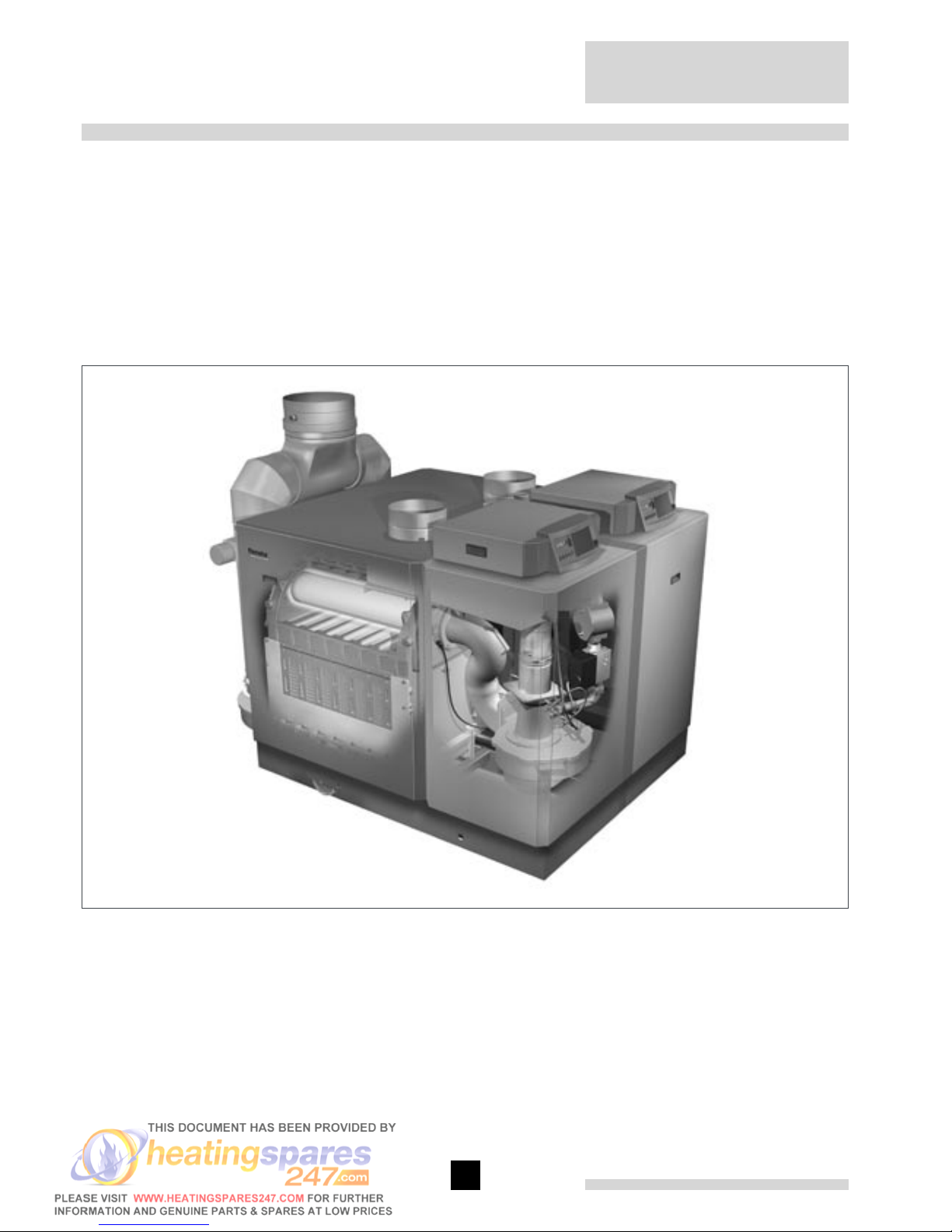
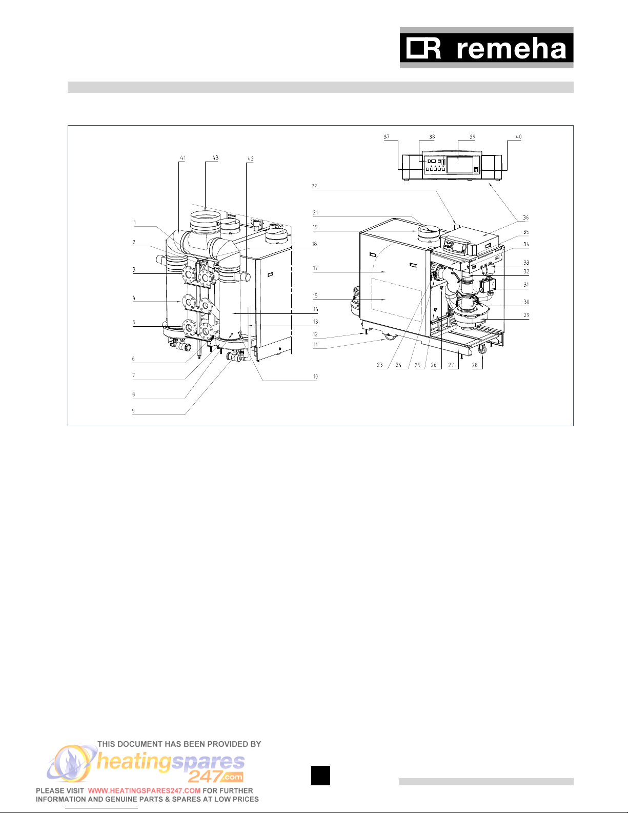
fig. 02 Cross-section Remeha Gas 610 ECO
00.61H.79.00002
All of the parts listed below apply for each boiler module
unless otherwise stated.
1. Pressure gauge
2. Pocket for external temperature sensor (7mm i/d
plain pocket)
3. Flow connection
4. 2nd Return connection (Optional)
5. Return connection
6. Filling/ drain cock
7. Condensate collector
8. Flue gas temperature sensor
9. Condensate drain
10. O2/ CO2 measuring point
11. Positioning wheels
12. Jacking bolts
13. Condensate drain hose
14. Flue gas discharge
15. Inspection hatch
17. Heat exchanger
18. Flow temperature sensor
19. Air supply
21. Air supply grille
22. Gas connection
23. Inspection glass
24. Ignition/ionisation electrode
25. Return temperature sensor
26. Boiler block temperature sensor
27. Frame
28. Steering castor
29. Fan
30. Venturi
31. Gas valve multiblock
32. Non return valve
33. Gas filter
34. Air pressure differential sensor (LDS)
35. Air box
36. Instrument panel
37. Control keys
38. Read-out window
39. Weather compensator installation (optional)
40. On/ off switch
41. Flue gas collector
42. Flue gas damper
43. Common flue gas discharge connection with
integrated condensate collector connected to
one of the siphons

Remeha Gas 610 ECO
8
9
3.2 Operating principle of each module
Combustion air is drawn into the inlet connection from
the plant room (room ventilated version) or from outside
via the eccentric flue system (room sealed) by the air
supply fan of each boiler module.
On the inlet side of the fan is a specially designed
chamber (venturi unit) which takes gas from the multiblock and mixes it in the correct proportions with the
incoming air. This mixing system ensures that the correct gas/ air ratio is delivered to the pre-mix burner at all
times.
Depending on demand (under the dictates of flow/return
sensor and other external/internal control inputs) the
'abc®' system of each boiler module determines the
required output of the boiler module. The 'abc®' control then varies the speed of the air supply fan which
alters the volume of air being drawn into the venturi, this
change in volume is measured using air pressure differential which directly controls the volume of gas also
being delivered to the venturi. The resultant controlled
mixture is delivered to the premix burner.
This mixture is initially ignited by the combined ignition/
ionisation probe, which monitors the state of the flame.
Should the flame be unstable or not ignite within the
pre-set safety time cycle the controls will (after 5
attempts) shut the boiler module down requiring manual
intervention to reset the boiler module. The digital display will indicate a flashing fault code confirming the
reason for the failure.
The products of combustion in the form of hot flue gases
are forced through the heat exchanger transferring their
heat to the system water, (the flue gas temperature is
reduced to approximately 5/ 8° above the temperature
of the system return water) then discharged via the condensate collector, to the flue gas outlet connection, to
atmosphere.
Because of the low flue gas exit temperature there will
be a vapour cloud formed at the flue gas terminal -this
is not smoke-, simply water vapour formed during the
combustion process.
If the flue gas temperature falls below dew point (55°),
water vapour (created during the combustion process)
will begin to condense out in the boiler module, transferring its latent heat into the system water, thereby
increasing the output of the boiler module without
increasing the gas consumption.
Condensation formed within the boiler modules and
flue systems is discharged from the boiler module to an
external drain via the drain pans and siphons supplied.
The flue gas discharges of the separate modules come
together in the flue gas collector, which can be connected horizontally as well as vertically.
Each boiler module can be supplied, as an option with
a second (constant temperature) return connection.
This additional connection enables the boiler
module to make full use of its condensing ability
whilst accepting both fixed and variable temperature
returns from the same system. A condensate
collector is situated above the flue gas collector.
This condensate collector is connected to 1 of the
siphons. fig. 01
9
4 TECHNICAL DATA
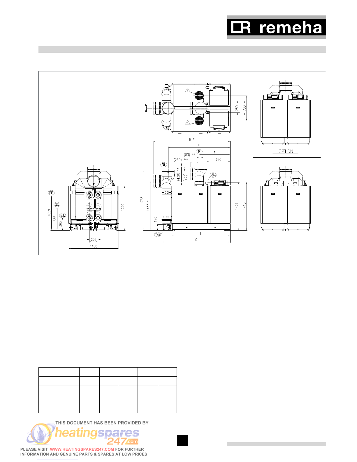
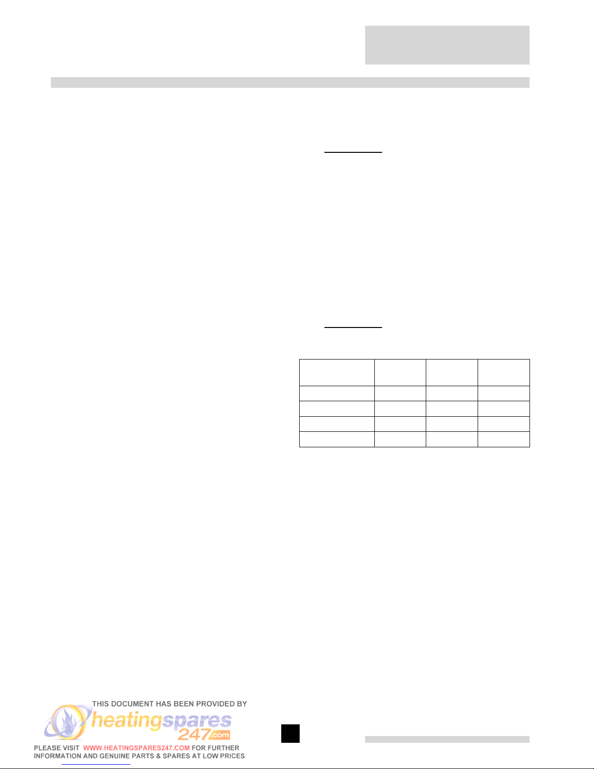
4.1 Dimensions
fig. 03 Elevation drawings
00.61H.79.00001
É Flow connection 2 x NW 80, DIN 2576
Ê Return connection 2 x NW 80, DIN 2576
Ï Gas connection 2 x 2” BSP (F)
Ò Condensate drain 2 x 1 ” nb plastic waste
Ñ Flue gas discharge 350 mm i/d
Ð Combustion air supply 2 x 250 mm i/d (standard); 1 x 350 mm (option)
Ì Second return connection (optional) 2 x NW 65, DIN 2576
* = Alternative horizontal flue gas discharge
** = Alternative combined vertical air supply
*** = Alternative combined horizontal air supply
g = Room sealed operation: remove grid
Boiler type A B C E L
2 x 6 sections 1600 1463 1590 901 1312
2 x 7 sections 1990 1853 1980 1110 1702
2 x 8 sections 1990 1853 1980 1007 1702
2 x 9 sections 1990 1853 1980 904 1702
table 01 Dimensions in mm
Remeha Gas 610 ECO
10
11
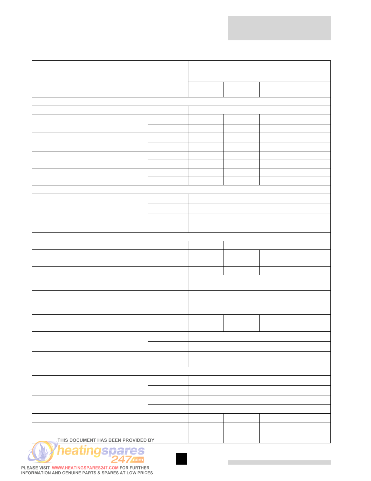
4.2 Technical data
Boiler type Unit
Remeha Gas 610 ECO
2 x 6 sec-
tions
2 x 7 sec-
tions
2 x 8 sec-
tions
2 x 9 sec-
tions
General
Boiler control options - Modulating, 2-stage or 4-stage
Nominal output Pn (80/ 60°)
min kW 87 123 122 148
max kW 654 790 924 1062
Nominal output Pn (50/ 30°)
min kW 94 131 130 156
max kW 706 854 998 1146
Nominal input Qn (GCV/ Hs) min kW 101 142 141 170
max kW 744 896 1046 1196
Nominal input Qn (NCV/ Hi) min kW 91 128 127 153
max kW 672 808 942 1078
Efficiency (Hi)
Combustion (Hi) at 80/ 60°
% up to 99
Heat to water (Hi) at 80/ 60°
% up to 98,5
Standing losses (T
average
= 45°)
% < 0.3
Annual efficiency (Hi) % 108,9
Gas and flue gas side
Gas category - Natural gas only
Inlet pressure gas (boiler running) min mbar 17
max mbar 100
Gas consumption m
0
3
/ h 74 86 100 114
NO
X
emission* (DIN 4702 p.8; annual
emissions)
mg/ kWh < 60
NO
X
emission* (DIN 4702 p.8; annual
emissions, O2 = 0%, dry)
ppm < 35
Residual fan duty Pa 130
Flue gas mass min kg/ h 153 215 214 257
max kg/ h 1130 1360 1586 1814
Flue gas temperature at 80/ 60°
min
°
57
max
°
65
Type classification due to discharging flue
gasses
- B23, C33, C43, C53, C63, C83
Water side
Flow temperature High Limit
°
110
Operating
°
20 - 90
Operating pressure min bar 0.8
max PMS bar 6
Water contents litres 120 142 164 186
Water resistance at 11° dT
mbar (kPa) 364 (36.4) 397 (39.7) 364 (36.4) 413 (41.3)
Water resistance at 20° dT
mbar (kPa) 110 (11) 120 (12) 110 (11) 125 (12.5)
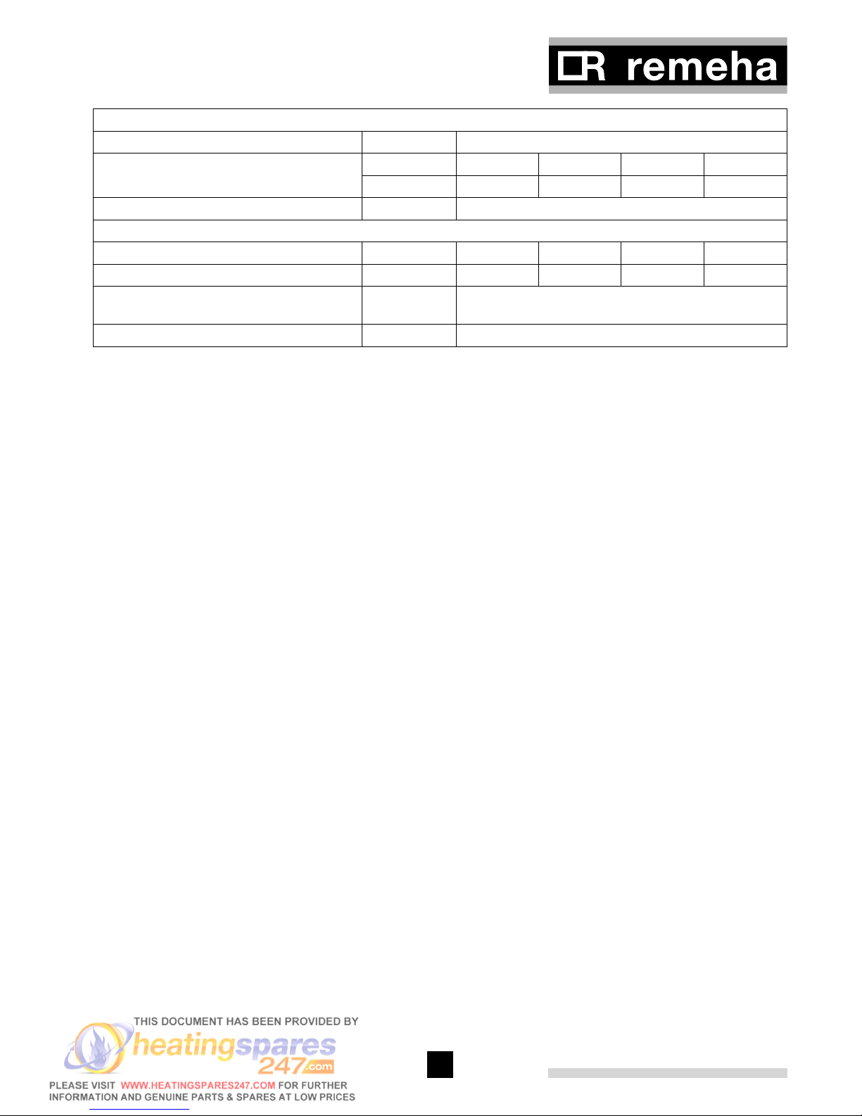
11
Electrical
Mains supply* V/Hz 230/ 50
Power consumption min Watt 24 24 24 24
max Watt 694 980 1240 1684
Insulation class IP 20
Other
Weight dry kg 820 920 1020 1120
Floor area m
2
2.4 2.4 2.8 2.8
Noise level at a distance of 1 m from the
boiler (average)
dB(A) 63
Colour of casing RAL 2002 (red); 9023 (grey)
table 02 Technical data Remeha Gas 610 ECO
Note: * for each boiler module
4.3 Quotation specification
- Cast aluminium - sectional pre-mix gas fired fully
condensing, modulating floor standing boiler consisting of 2 individual modules within one casing
and with a common flue gas outlet
- Sectional heat exchangers manufactured from cast
aluminium
- Maximum operating pressure of 6 bar
- Maximum operating temperature of 90°C
- Ultra low NOx (max. 35 ppm at 0% O
2
)
- Pre-mix, fully modulating (each module 30 - 100 %)
gas burners with unique gas/ air ratio control for maximum efficiency
- Intelligent advanced boiler controls ‘abc®’ c/w a comprehensive operating, service and fault diagnostic
facility
- No minimum flow requirement (see section 7.4.5)
- Available as conventional flue or room sealed operation
- Capable of remote BMS control (0 -10V modulating,
2-stage or 4-stage option)
- Each module has a socket for advanced service diagnostics (for PC/ PDA connection)
- Each boiler module supplied fully factory assembled
and tested
- Powder coated enamel steel casing BS; RAL colour:
2002 (red); 9023 (grey)
- Rigid steel box frames
- Suitable for use with Natural gas only
- Each boiler module supplied as standard with on/
off switch, temperature indication, flow, return, heat
exchanger block and flue gas sensors
- Supplied as standard with indicating module No. 1
lock-out indication (Volt free), shut down indication
(Volt free), boiler on indication (24 Volt AC)
- Efficiencies up to 109% (NCV/ Hi)
- Manufactured to ISO 9001
- CE approved
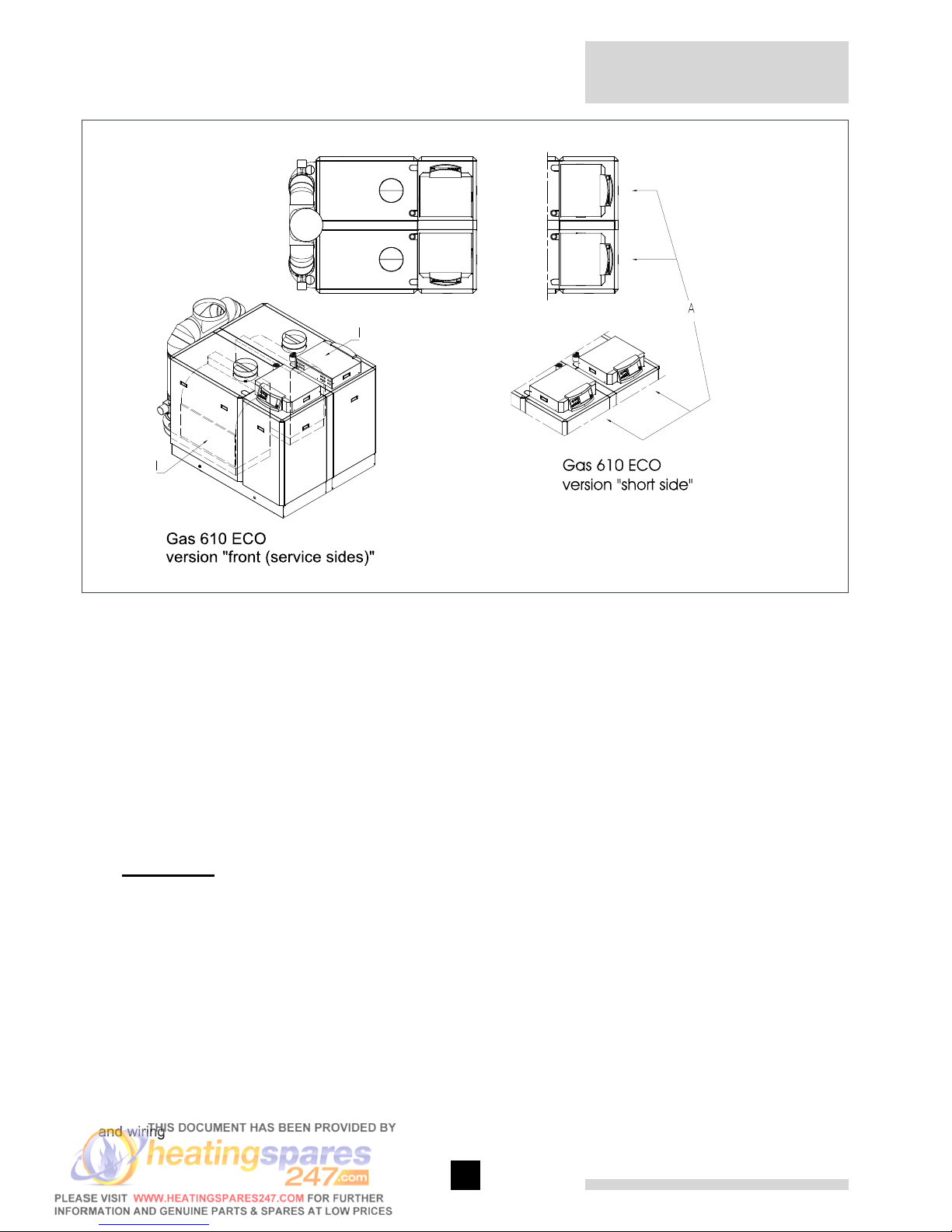
4.4 Delivery options
Available in 4 section sizes, each with 2 instrument
panel positions:
Remeha Gas 610 ECO
12
13
fig. 04 Installation options
00.61H.79.00003
I = Front (service sides)
A = Short side (alternative orientation of the instrument
panel)
The service side with the inspection cover on the heat
exchanger is considered to be the front of each boiler
module.
The boiler instrument panel can be rotated to face the
front or the short side of the boiler module (front will be
standard unless stated on the purchase order) (see fig.
04).
g Important!!
When ordering a Remeha Gas 610 ECO, it is essential
that the number of sections and the orientation of the
instrument panel are required.
4.5 Accessories
- Modulating weather compensators
- Second return connection*
- System pressure sensor*
- Vertical room sealed terminal VRS (2 x ø 350)
- Common air supply adapter for room sealed opera-
tion (ø 350)
- Condensate neutralisation box
- Condensate neutralisation granules
- Recom communication set with CD-ROM, interface
and wiring
- Interfaces for communication with various controllers
(see section 8.6)
- Gas leak proving control*
- Minimum gas pressure switch*
- Cleaning tools
- Air supply filter*
Note: * These accessories must be ordered in pairs (one
for each module)

13
5 EFFICIENCY INFORMATION
5.1 Annual efficiency (92/42EEC)
Up to 108.9% at Hi (up to 97% at Hs) at an average
water temperature of 40°C (50/ 30°C).
5.2 Heat to water efficiency (92/42EEC)
a. Up to 98.5% at Hi (88% at Hs) at an average water
temperature of 70° (80/ 60°).
b. Up to 106.4% at Hi (98% at Hs) at an average water
temperature of 40° (50/ 30°).
5.3 Standing losses
Less then 0.3% at Hi (0.33% at Hs) at an average water
temperature of 45°
Note: NCV = Hi, GCV = Hs
6 APPLICATION DATA
The Gas 610 ECO can be used on all new and refurbishment projects in both single and multiple configurations. Conventional and room sealed flue system capability means that the boiler modules can be sited almost
anywhere within a building.
The Remeha weather compensators (option) are able to
communicate directly with the boiler’s controls to make
full use of their fully modulating features, ensuring that
the boiler module closely matches the system demand
at all times.
External control systems (BMS) can be interfaced with
the boiler modules to provide 2-stage or 4-stage or modulating (0 -10V) control options.
Remeha Gas 610 ECO
14
15
7 INSTALLATION INSTRUCTIONS FOR HEATING INSTALLER
7.1 General
All gas appliances must, by law, be installed by competent persons (e.g. Corgi registered). Failure to install
appliances correctly could lead to prosecution.
It is in your own interest and that of safety to ensure that
the law is complied with.
The following instructions must be adhered to when the
Remeha Gas 610 ECO is installed:
- Gas Safety (Installation and Use) Regulations 1984
(as amended).
In addition to the above regulations, this boiler must be
installed in compliance with:
- Current I.E.E. Regulations for electrical installations
- Local building regulations
- The Building Standards (Scotland)
- (Consolidation) Regulations
- By-laws of the local water undertaking
- Health and Safety Document No 635 ‘The Electricity
at Work Regulations 1989’
It should also be in accordance with the relevant recommendations in the current edition of the following British
Standards and Codes of Practice, viz. BS 6644, BS5978
Part 1 & 2, BS 5449, BS 5446, BS 6798, BS 6891 and
BG DM2.
Important:
The Remeha Gas 610 ECO is a CE certified boiler and
must not be modified or installed in any way contrary to
these “Installation and Maintenance Instructions”.
Manufacturers Instructions must NOT be taken as overriding statutory obligations.
7.2 Delivery and installation
The Remeha Gas 610 ECO is supplied in 2 crates, with
a module in each crate. The flue gas collector is supplied separately on a pallet. The overall dimensions of
the crates are 80 cm wide and 175 cm high with the
length dependant on the number of sections (2 x 6 sections: 170 cm, 2 x 7 to 9 sections: 209 cm). The base
of the crate packaging is a 76-cm wide pallet to enable
it to be transported with a pallet truck, forklift truck or 4wheel transport boards.
Excluding the crate each boiler module is 72-cm wide
c/w casing panels and 70 cm without casing and will fit
through most standard doors (minimum door opening
width 80 cm). Each boiler module has wheels so that,
once the packaging has been removed, it can easily be
moved around on a smooth surface.
i The pallet lid can be used as a rocking ramp
to convey the boiler module over obstacles, such as
thresholds etc.
g Important!! The wheels are designed for
transport purposes only and MUST NOT be used when
the boiler module is in its final position!
Once in position the boiler modules are fixed into position using the fitted jacking bolts which both raise the
wheels of the ground and level the boiler modules.
Technical documentation is supplied with the boiler in
a holder on the inside of the boiler casing (beneath an
instrument panel). A number of small loose components,
such as the flue gas collector, the flue gas dampers, the
plinths and the 8 support pads have been placed on the
extra pallet.
Use the plastic packaging to protect the boiler until
required for use.
g Important!! Additional protection may be
required if site conditions warrant it – overhead builders
working, insulation etc.
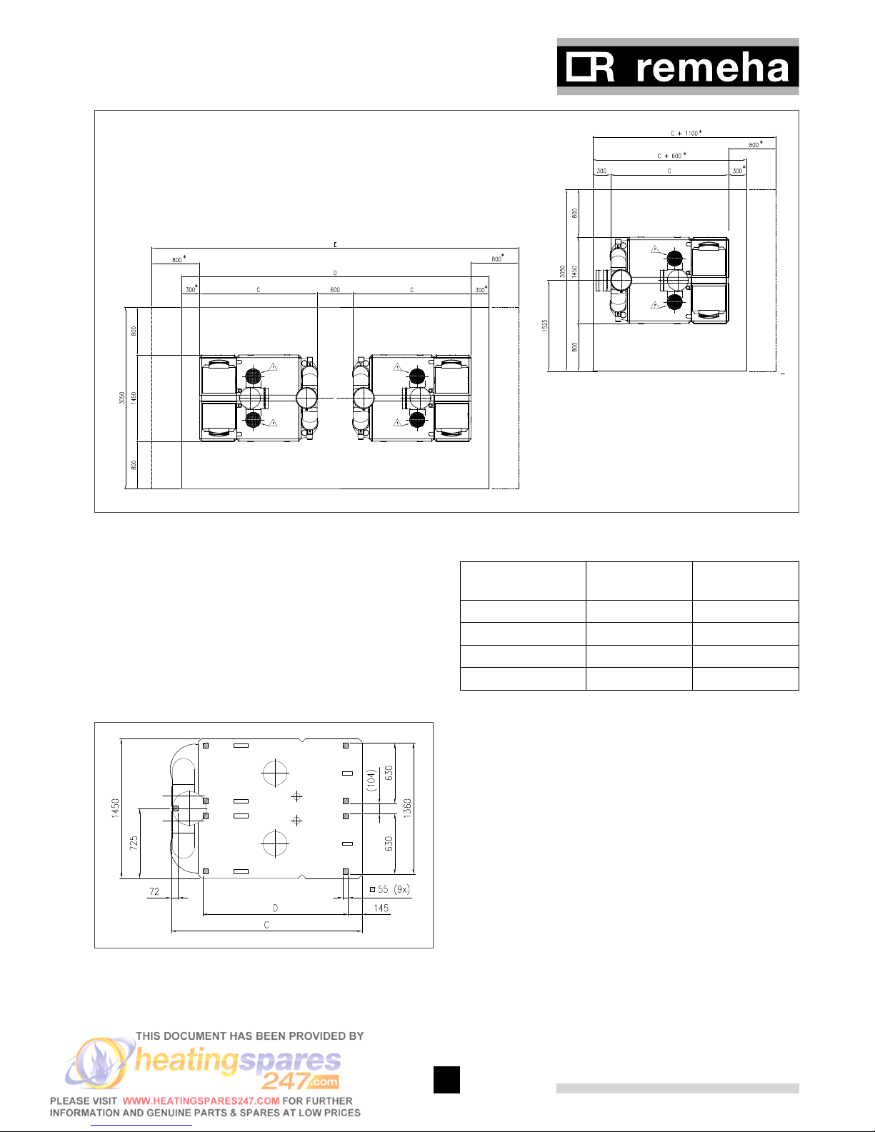
Number of sec-
tions
C in mm D in mm E in mm
2 x 6 1590 4380 5380
2 x 7 1980 5160 6160
2 x 8 1980 5160 6160
2 x 9 1980 5160 6160
* Free space 800 mm, if instrument panel is facing the
short side.
g Remove air inlet plates for room sealed installa-
tions
15
fig. 05 Layout in the boiler room
00.61H.79.00004
Clearance of at least 800 mm is required at the front
(service side) of each boiler module. However, we recommend a clearance of 1 m. A clearance of at least 400
mm above the boiler and at least 300 mm on both ends
(800 mm if the instrument panel is rotated to face the
short end).
fig. 06 shows the boiler’s support area including the
position of the support pads (shaded boxes) supplied.
fig. 06 Support area Remeha Gas 610 ECO
00.61H.79.00005
Number of sec-
tions
C in mm D in mm
2 x 6 1590 1118
2 x 7 1980 1508
2 x 8 1980 1508
2 x 9 1980 1508
table 03 Base dimensions

Remeha Gas 610 ECO
16
17
7.3 Flue gas discharge and air supply
7.3.1 General
The Remeha Gas 610 ECO is suitable for both conventional room ventilated or eccentric room sealed operation.
Room sealed terminals should comply with the Gastec
QA-requirements for vertical outlet constructions.
Any horizontal pipework in the flue gas discharge system should slope towards the boiler.
Horizontal pipework in the air supply system should
slope towards the supply opening and may require a
drain point at the low point.
Care should be taken when siting flue exit positions as
a vapour plume will be visible when the boiler is operational (flue gas temperature will be less than < 77°
resulting in the water vapour condensing out on contact
with the air).
7.3.2 Classification due to discharging flue gases
Classification according to CE:
Type B23: Conventional room ventilated appliance without draft diverter. Air supply from boiler room; flue gas
discharge on roof.
Type C33: Room sealed appliance, connected to combined roof outlet.
Type C43: Room sealed appliance in cascade configuration, connected via two ducts to a common duct system serving more than one appliance.
Type C53: Room sealed appliance, connected to separate ducts for the air supply and flue gas discharge, terminated in zones of different pressure.
Type C63: Room sealed appliance, supplied without the
terminal or the air supply and flue gas discharge ducts.
Type C83: Boiler with room sealed operation, connected
to separate air supply and flue gas discharge duct, with
flue gas discharge duct always in depression.
Conventional flue or room ventilated installations:
A room-ventilated boiler takes the required combustion
air from the plant room. Combustion air for the boiler
module must be provided to the room/ compartment in
accordance with BS 6644. A table showing the maximum discharge lengths for the room ventilated version
of the Remeha Gas 610 ECO can be found in section
7.3.6.
Room sealed installations:
It is unnecessary to provide separate combustion air to
the room/compartment as this is supplied direct to the
boiler via the eccentric flue and air inlet system to the
vertical terminal unit (see fig. 09, VRS 350 option available from Broag).
Additional ventilation will be required to the room/
compartment in accordance with BS 6644 (compartment
ventilation).
For installations where supply and discharge points are
in two different pressure zones CLV system please contact Broag Technical Dept. for further details and advice.
Note: The boilers can also be installed on a flue dilution system, but must incorporate a total flue break to
avoid boiler gas/air ratio controls being affected by the
flue dilution fan pressures. For full details please contact
Broag.
A table showing maximum air supply/ flue gas discharge
lengths for the room sealed version of the Remeha Gas
610 ECO can be found in section 7.3.7.
7.3.3 Connection options
The Remeha Gas 610 ECO is available in a room ventilated and a room sealed version. If the room-sealed
version is used, the 2 grilles must be removed before
installing the optional common air inlet connection.
7.3.4 Inlets/Outlets
For conventional flue systems the flue terminal exit point
should discharge vertically and be c/w a tapered cone
and bird guard. For room sealed options use the Broag
VRS 350 vertical terminal (see fig. 09).
7.3.5 Other requirements
Flue gas discharge materials:
Single wall, rigid: stainless steel, thick-walled aluminium
(to comply with building regulations).
Flexible : stainless steel (to comply with building
regulations).
Flue gas discharge structure:
The flue gas discharge pipe must have airtight and
watertight joints and connections and should be seamless.
Horizontal sections in the flue gas discharge pipe must
slope down towards the boiler (at least 5-cm per meter).
Flue liners:
If flue liners are used they must be manufactured from
stainless steel or flexible plastic (continuous operating temperature rating of 120°) and be gas and water
tight).
Air supply materials:
Single wall, rigid or flexible: aluminium, stainless steel.
Air supply structure:
The air supply pipe must also be airtight. Horizontal sections in the air supply must slope away from the boiler
module towards the supply opening and incorporate a
drain connection if the route rises from a lower point that
could flood.
17
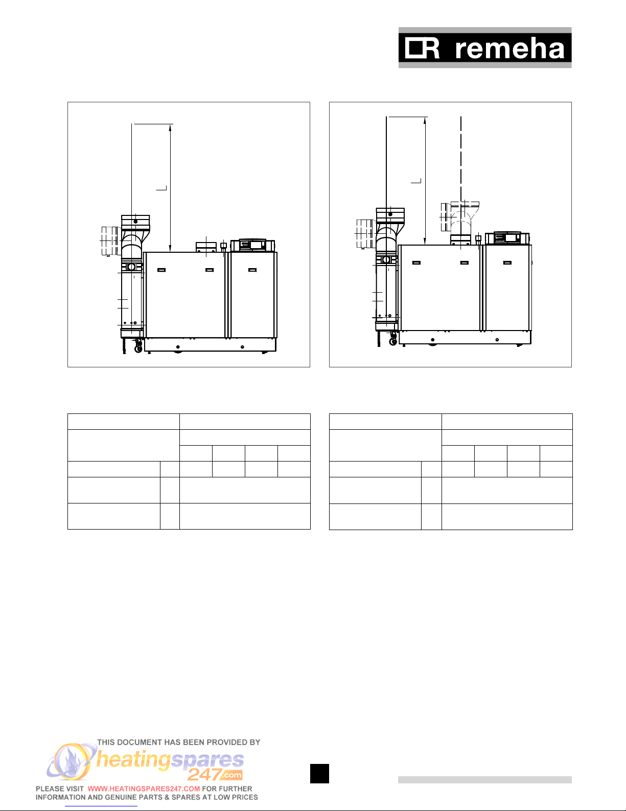
7.3.6 Single boiler conventional flue
fig. 07 Flue gas discharge duct without bends, single
boiler, conventional flue.
00.31H.79.00011 (afb 1)
Flue diameter 350 mm
Model Gas 610 ECO
Sections
2 x 6 2 x 7 2 x 8 2 x 9
max eq. length L m 286 183 122 81
eq. length bend 45°
R=D
m 3.2
eq. length bend 90°
R=D
m 5.6
table 04 Calculation data conventional flue
Example: Gas 610 ECO, 2 x 9 sections, total length 44
m, diameter 350 mm, 2 bends 90°.
44 m + 2 x 5.6 = 55.2 < 81 m → flue OK.
Note: If the design parameters are outside the values shown in the above table or there is any doubt
over the flue system, please contact our technical
department for calculation to be undertaken.
7.3.7 Single boiler, room sealed flue
fig. 08 Flue gas discharge duct without bends, single
boiler, room sealed application.
00.31H.79.00011 (nr 6)
Flue/ air inlet diameter 350/350 mm
Model Gas 610 ECO
Sections
2 x 6 2 x 7 2 x 8 2 x 9
max eq. length L m 134 79 46 24
eq. length bend 45°
R=D
m 3.2
eq. length bend 90°
R=D
m 5.6
table 05 Calculation data room sealed applications
Example: Gas 610 ECO, 2 x 7 sections, total length flue
52 m, 2 bends 90°.
52 m + 2 x 5.6 = 63.2 < 79 m → flue OK.
Note: If the design parameters are outside the values shown in the above table or there is any doubt
over the flue system, please contact our technical
department for calculation to be undertaken.
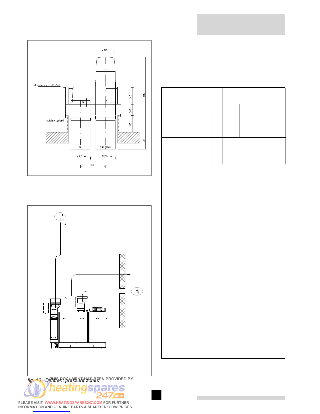
A combined vertical terminal set and roof sealing plate
for flat roofs, are available for the room-sealed version
with diameters of ø 350/ ø 350 in accordance with the
drawing below.
Remeha Gas 610 ECO
18
19
fig. 09 Vertical terminal for room sealed operation
04.60H.79.00002
7.3.8 Different pressure zones
Ñ Flue gas discharge
Ð Combustion air supply
fig. 10 Different pressure zones
pdf
\
The Remeha Gas 610 ECO boilers are capable of operating with the air inlet and flue outlet in different pressure zones (CLV System).
The max height difference between air inlet and flue gas
outlet is 36 meters and the maximum total length of air
inlet and flue gas outlet pipework L is shown in table 06.
Flue/ air inlet diameter 350 / 350 mm
Sections
Model Gas 610 ECO 2 x 6 2 x 7 2 x 8 2 x 9
maximum total
length of air inlet and
flue gas outlet pipework L
m 168 78 24 -
eq. length bend 45°,
R=D
m 3.2
eq. length bend 90°,
R=D
m
5.6
table 06 Different pressure zones
Note: this system may not be used in areas with
adverse wind conditions (i.e. in some coastal regions).
Note: If the design parameters are outside the values
shown in the above table or there is any doubt over the
flue system, please contact our technical department for
calculation to be undertaken.
7.3.9 Header flue systems
For multiple boiler installations with common flue systems please refer to Broag for advice.
7.4 Installation details
7.4.1 Water pressure
The individual boiler sections are each subjected to
a test pressure of 10 bar. On assembly the complete
block is subjected to a factory pressure test using compressed air at 2 bar for 1 minute.
The boiler is suitable for a maximum working pressure
of 6 bar.
7.4.2 Condensate discharge
Discharge the condensate via a tundish, directly into
a drain. Only use synthetic material for the connecting
pipework because of the acidity (pH 2 - 5) and allow a
min. of 30 mm per meter fall to ensure a good flow rate.
Fill the siphons with clean water before firing the boiler
modules.
It is not advisable to discharge into an outside gutter,
because of the risk of freezing.
 Loading...