

Reliable NS-ASAM, NS-Pak, Nitrogen Regulator Bulletin
Product Features
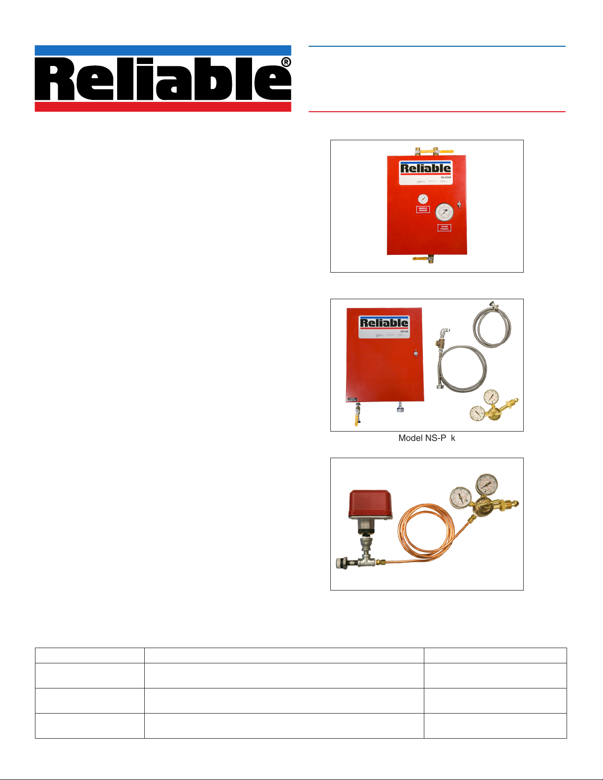
NS-ASAM
• Designed for two separate nitrogen or air sources
• Automatically switches between primary and secondary
source
• Bypass valve provided for quick fill of system
• Low-pressure switch for primary source
• For use on single or multiple systems
• Keyhole slots provided for easy wall mounting
Bulletin 254 May 2019
Nitrogen Automatic Pressure
Maintenance Devices
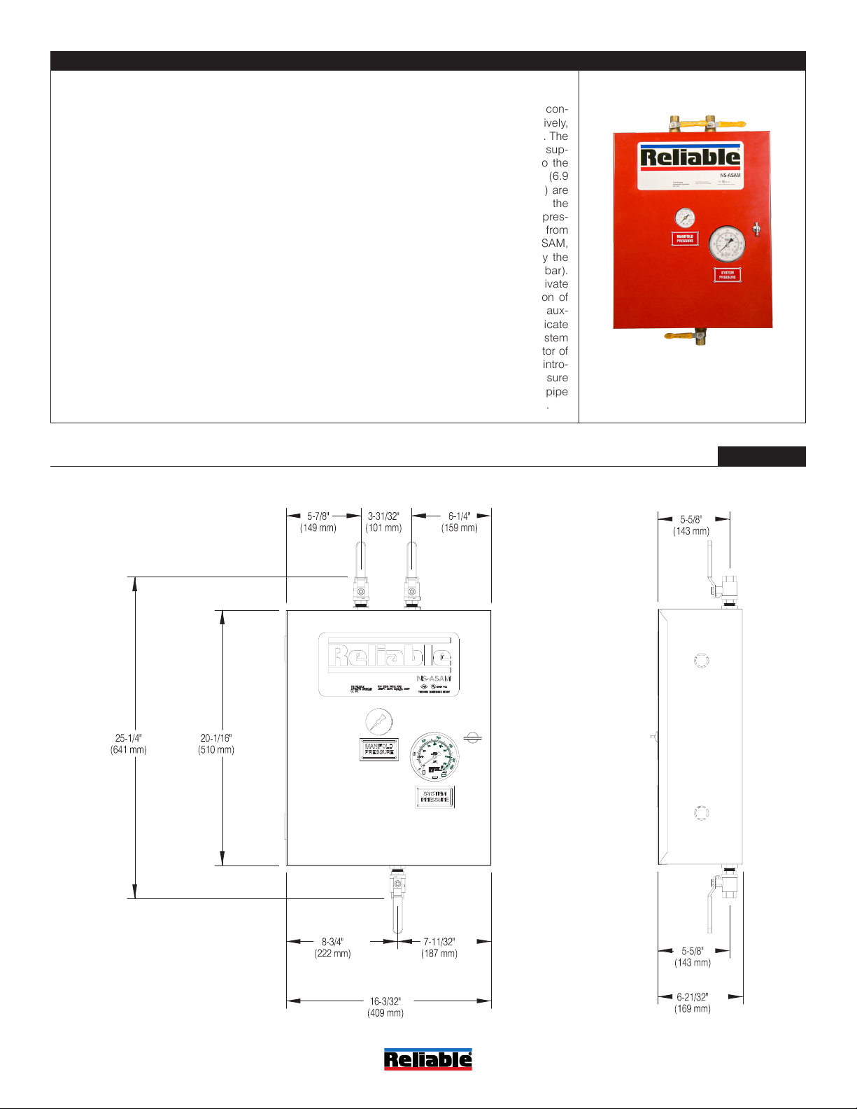
NS-Pak
• For bottled nitrogen use on a single system
• Low-pressure switches for nitrogen source and system
• Bypass valve provided for quick fill of system
• Keyhole slots provided for easy wall mounting
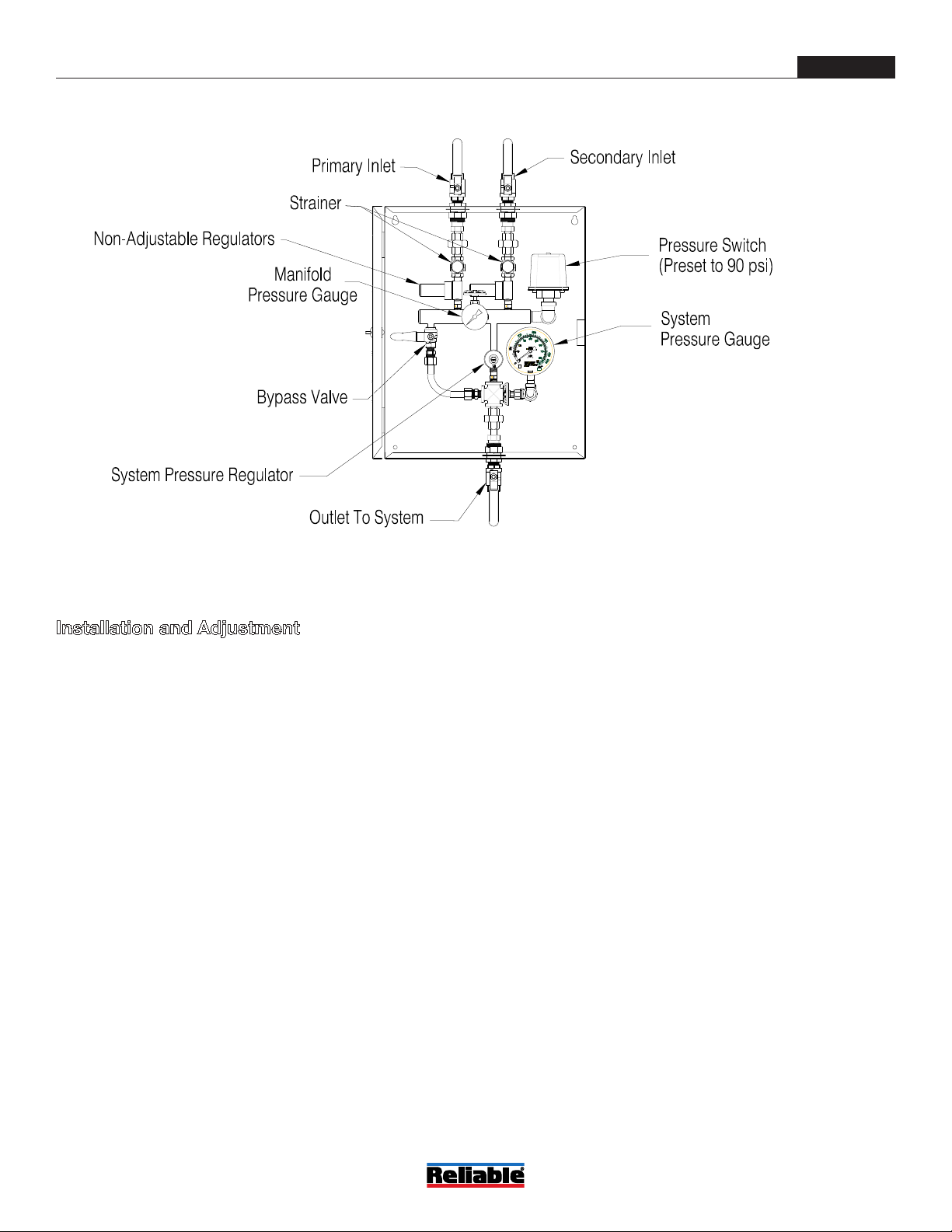
Nitrogen Regulator
• For bottled nitrogen use on single or multiple systems
• Low-pressure switch for nitrogen source
General Description
Reliable Nitrogen Automatic Pressure Maintenance Devices
are designed to connect nitrogen cylinders to dry pipe and
preaction systems. The NS-ASAM is designed to connect a
primary and secondary cylinder or bank of cylinders to single or multiple systems, and provides automatic switchover
between sources. The NS-Pak is a self-contained unit for connection of a cylinder or bank of cylinders to a single system.
The Nitrogen Regulator reduces cylinder pressure and can
be connected to the A-2 Pressure Maintenance Device on
single or multiple systems. Each device includes a low-pressure switch to signal that the nitrogen source is depleting and
needs service. High-pressure cylinders (not included) can
typically be obtained from a local source.
Model NS-ASAM
Model NS-Pak
Nitrogen Regulator
Model Product Description Listing and Approvals
NS-ASAM Nitrogen maintenance device with automatic switchover
NS-Pak
Nitrogen Regulator
Single system nitrogen maintenance device with high pressure
regulator
High-pressure regulator for connection to single or multiple pressure
maintenance devices
www.reliablesprinkler.com
cULus Listed
FM Approved
cULus Listed
FM Approved
N/A
Model NS-ASAM
Technical Specifications
Threads: 1/2” NPT
Min. Inlet Pressure: 100 psi (6.9 bar)
Max. Inlet Pressure: 250 psi (17.2 bar)
Min. Outlet Pressure: 10 psi (0.7 bar)
Max. Outlet Pressure: 70 psi (4.8 bar)
Listings and Approvals
cULus Listed
FM Approved
System Operation
Primary and secondary sources of nitrogen or air are con-
nected to the primary and secondary inlets, respectively,
of the Model NS-ASAM Pressure Maintenance Device. The
primary and secondary nitrogen or air sources should sup-
ply a recommended pressure of 120 psi (8.3 bar) to the
NS-ASAM, although a minimum pressure of 100 psi (6.9
bar) up to a maximum pressure of 250 psi (17.2 bar) are
permitted. The NS-ASAM will admit nitrogen or air from the
primary source, until the primary source depletes to a pres-
sure of approximately 80 psi (5.5 bar). Nitrogen or air from
the secondary source is admitted through the NS-ASAM,
when the pressure of the nitrogen or air supplied by the
primary source is less than approximately 80 psi (5.5 bar).
A pressure switch in the NS-ASAM is factory-set to activate
at a pressure of 90 psi (6.2 bar) to indicate depletion of
the primary source. The pressure switch includes an aux-
iliary set of contacts that may be field adjusted to indicate
loss of pressure from the secondary source. The system
pressure may be set with the system pressure regulator of
the NS-ASAM. A bypass valve is provided to rapidly intro-
duce nitrogen or air into the system. Individual low-pressure
switches (not provided) should be installed in the dry pipe
or preaction valve trim to indicate low system pressure.
Model NS-ASAM Dimensions
Figure 1
Bulletin 254
May 2019
www.reliablesprinkler.com
Page 2 of 7
Model NS-ASAM Components
Figure 2
Installation and Adjustment
1. Securely mount the NS-ASAM enclosure to the wall using
the keyhole slots.
2. Confirm that all valves are closed.
3. Securely mount and properly pipe the primary and sec-
ondary sources of nitrogen or air in accordance with
appropriate local, state, or federal standards.
4. Connect the primary source of nitrogen or air to the prima ry inlet of the NS-ASAM and connect the secondary source
of nitrogen or air to the secondary inlet of the NS-ASAM.
5. Connect the NS-ASAM outlet to the port provided for pneu
matic supply to the sprinkler system (see note 1).
6. Before applying pressure to the sprinkler system, turn the
adjustment screw on the System Pressure Regulator within
the NS-ASAM fully counterclockwise.
7. Adjust the primary and secondary sources of nitrogen or
air to a recommended pressure of 120 psi (8.3 bar); the
minimum required inlet pressure is 100 psi (6.9 bar) and
the maximum rated inlet pressure is 250 psi (7.2 bar).
8. Open the Primary Inlet Valve and the Secondary Inlet
Valve.
9. Open the Bypass Valve and the NS-ASAM Outlet Valve to
allow nitrogen or air to flow into the system piping.
10. When the system pressure rises to within 2 psi (0.15 bar)
of the required system pressure, fully close the Bypass
Valve.
11. Slowly turn the adjustment screw of the System Pressure
Regulator clockwise to increase pressure to the level
required by the system. Tighten the lock-nut on the System
Pressure Regulator (see note 2).
12. If desired, supervise the contacts of the Pressure Switch in
accordance with NFPA 72 to provide notification that the
primary nitrogen or air source is depleted. The auxiliary
contacts of the pressure switch may also be supervised to
indicate depletion of the secondary source of nitrogen or
air. When supervising the auxiliary contacts, the primary
contacts of the pressure switch should remain at the
factory setting of 90 psi (6.2 bar) to indicate depletion of
the primary source and the auxiliary contacts should be
adjusted to a pressure setting of approximately 70 psi (4.8
bar).
13. If necessary, adjust the setting of the low-pressure switch
for each system.
14. Use a soap solution at all joints to verify leak-tight connec-
tions.
Notes:
1. When applying more that one system, each system must
have an individual Pressure Maintenance Device.
2. For multiple systems, the NS-ASAM system regulator must
be set a minimum of 5 psi above the highest system pres-
sure required. Use the regulator on the Pressure
Maintenance Device of each system to make final
adjustment.
Bulletin 254
May 2019
www.reliablesprinkler.com
Page 3 of 7
 Loading...