

Reliable MSK-8900H Instruction Manual
MSK-8900M
Industrial Sewing Machine
INSTRUCTION MANUAL

1. Brief introduction 1
2. Main specifications 1
3. Main parts name 1
4. The method of installation 1 5
5. Pareparation before sewing 5 7
6. Sewing 7 8
7. Adjusting the tension of thread 8
8. Maintenance 9 10
9. Correct adjustment 10 13
1. Machine casting components 14 15
2. Needle bar, thread take-up components 16 17
3. Presser foot components 18 19
4. Feed components 20 23
5. Rotary hook components 24 25
6. Lubrication components 26 27
7. Accessories 28 29
CONTENTS
Operation instruction
Parts manual

OPERATION INSTRUCTION
Needle bar
Thread take-up lever cover
Oil window
Hand wheel
Stitch dial
Feed lever
Pressure adjusting screw
Bobbin winder
Belt guard
2a2a
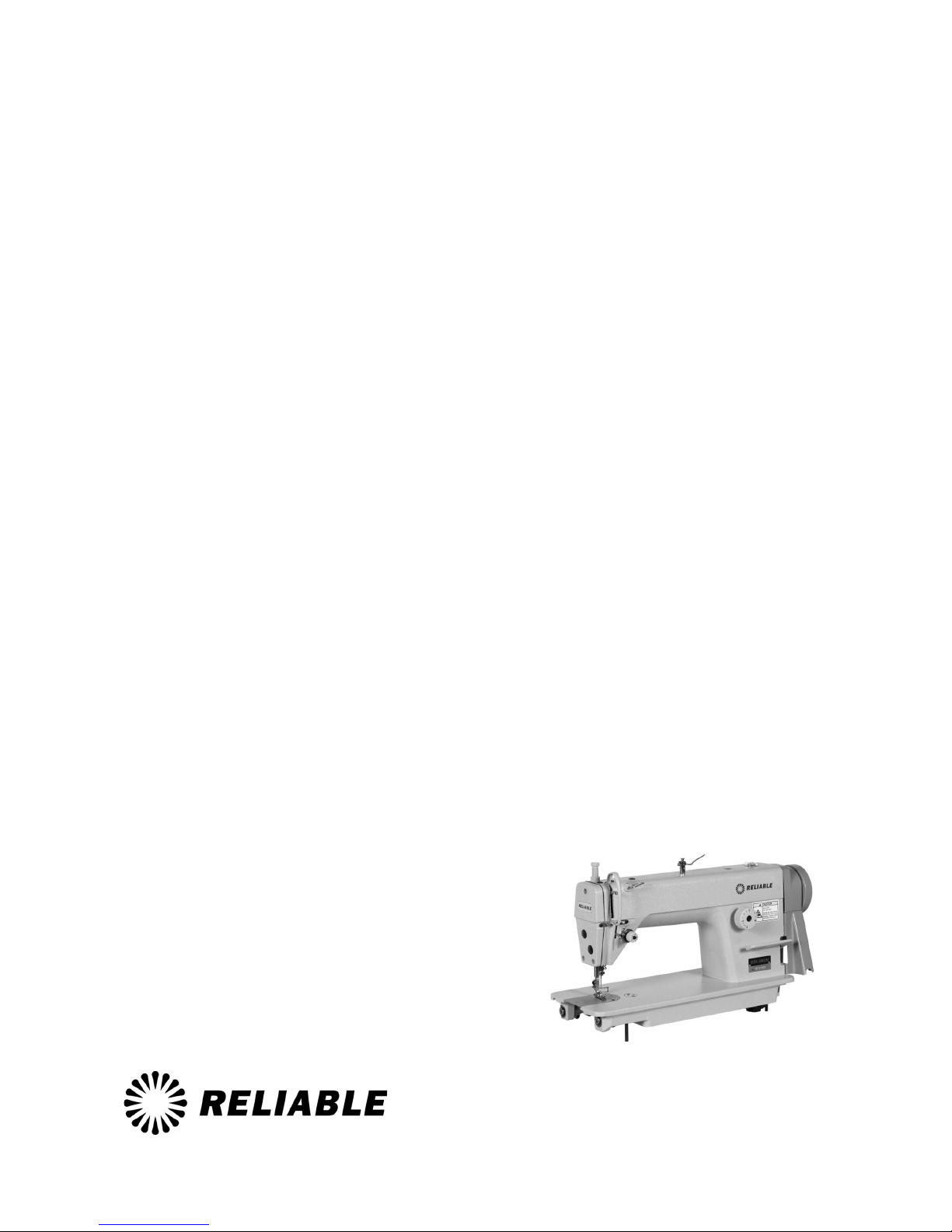
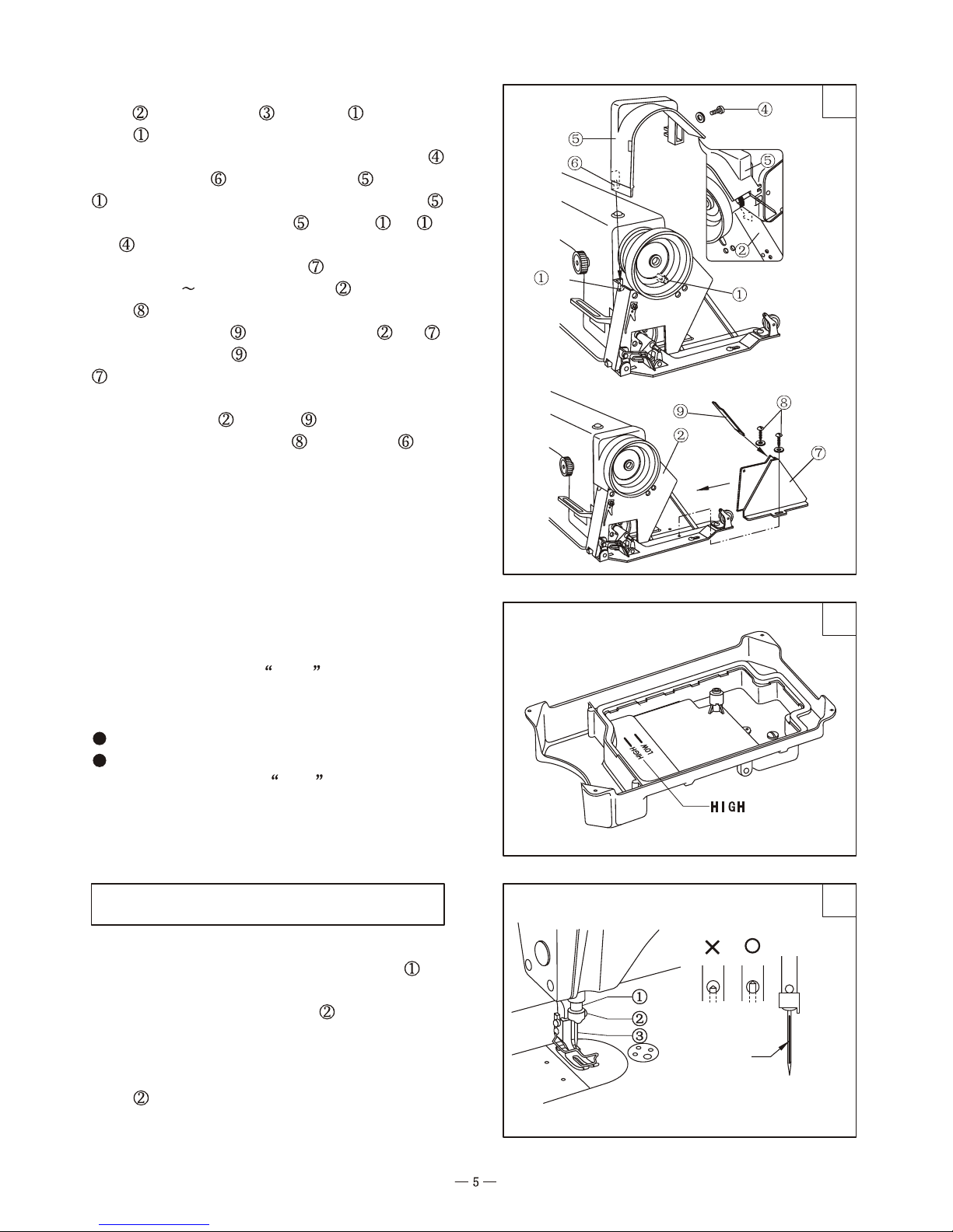
1. Installing the oil pan (Fig. 2)
(1) Put the vibration-proof pad (black) and
(double color) under the four corners of oil pan ;
11
2. Main specifications
1. Brief introduct oni
MSK-8900MMSK-8900M MSK-8900HMSK-8900H
Medium - and
heavy - weight
materials
ModelModel
Applications
Max. Sewing speed
Needle bar stroke
Max. Stitch length
Hook
Needle
Height of feed dog
Lubrication
Motor power
4200.s.p.m.
4.2mm 5mm
31mm
DB 1 14#
0.8mm 1.2mm
Automatic lubrication
3500.s.p.m.
35mm
DB 1 21#
370W
Heavy - weight
materials
Small auto - lubricating hook
Presser foot lift
height
6mm by hand
13mm by knee
MSK-8900M/H high speed straight lockstitch
sewing machine adopts single needle, needle bearing
link to take up thread, small hook to catch loop
which forms lockstitch seam. It features high precise
bevelgear for driving upper and lower shafts, dial
stitch length regulator, lever type forward and reverse
feed mechanism, full automatic lubricating system
assures reliable lubrication.
With the features of reasonable design, beautiful
apperance, precisely manufacture, little vibration
and lower noise, it s a good machine for the makers
of garments, suitcase, leather goods, shoes and caps,
etc.
3. Main parts name (Fig. 1)
4. The method of installation
1
1
2
3
4
1
2 3
4
5
6
7
8
9
33
(2) Put the oil pan into the cutouts of table
(3) put the machine casting hinge cushion into
the cutouts of table and fix it by nails .
and
fix it by nails ;
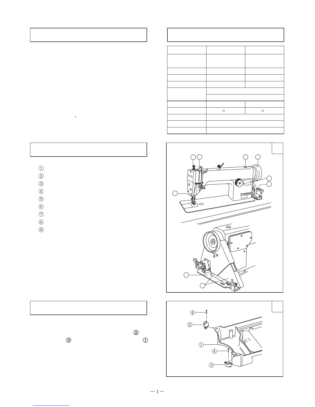
2. Installing the machine head (Fig. 3)
(1) Insert the knee lifting rod ;
(2) Insert the casting hinge to the hole in the
bed;
(3) Put the hinge in the cushion and put the
head on the pad ;
(4) Inset the machine head supporter in the table.
Notice:
Be sure to full inset the supporter in the table
Otherwise it may cause danger while put the
machine head down.
2b2b

55
66
44
3. Installing the knee lifter (Fig. 4)
Install the knee lifter on the knee lifter hinge
shaft and fix it by screw .
5. Installing the V-belt (Fig. 6)
(1) Lower the machine head and install the belt
on the hand wheel and motor pulley;
(2) Press the belt by forefinger with the power
of 4.9N (500gf), adjust the nut to make the belt
a slack of 10~14mm.
4. Adjusting the knee lifter mechanism (Fig. 5)
(1) Lay down the presser foot lifting bar to
lower the presser foot ;
(2) Loosen the nut ;
(3) Press the knee lifter plate cover to make
movement amount of the knee lifter positioning
bracket about 2mm, then adjust the screw ;
(4) After adjustment, tighten the nut .
(5) Loosen the nut ;
(6) Adjust screw to make its length above the
bracket 8mm;
(7) Adjust screw , the clearance between presser
foot and needle plate should be less than 13mm when
the knee lifter is pressed to its maximum position;
(8) After adjustment, tighten the nut .
77
88
9a9a
G
F
E
D
C
B
A
¡«¡«
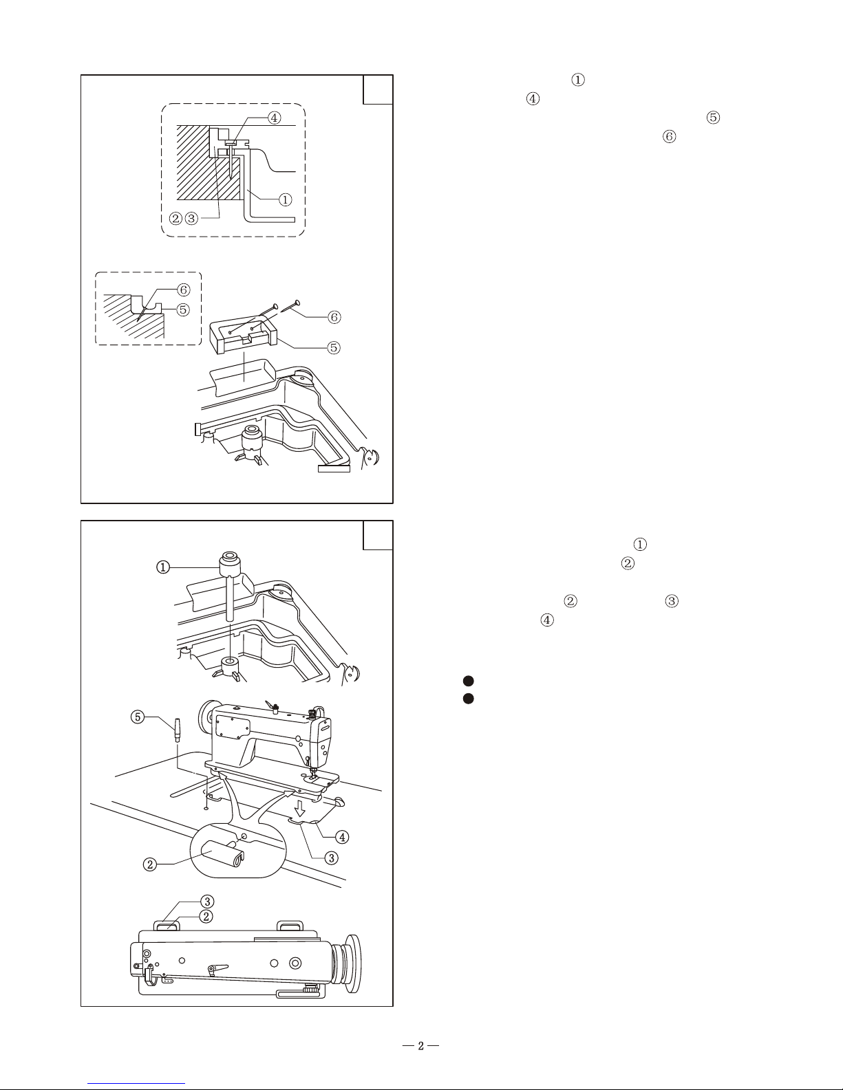
6. Connecting pedal with lever of clutch motor (Fig.7)
(1) The optimum tilt angle of pedal A against floor
is approx.20 ~30 .
(2) Adjust the clutch of motor E to make the rod B
and the clutch lever C run in one line.
(3) When runing, the machine balance wheel G
should rotate counter - clockwise observed form
opposite side of the balance wheel, the motor D
rotates in the same direction. The rotation of motor
can be reversed by reversing the plug of power ( turn
over 180 )
(4) Adjust the tension of V-belt F by moving the
motor upward or downward. The proper tension of
V-belt is a slack of 10~12mm when the V-belt is
depressed by forefinger.
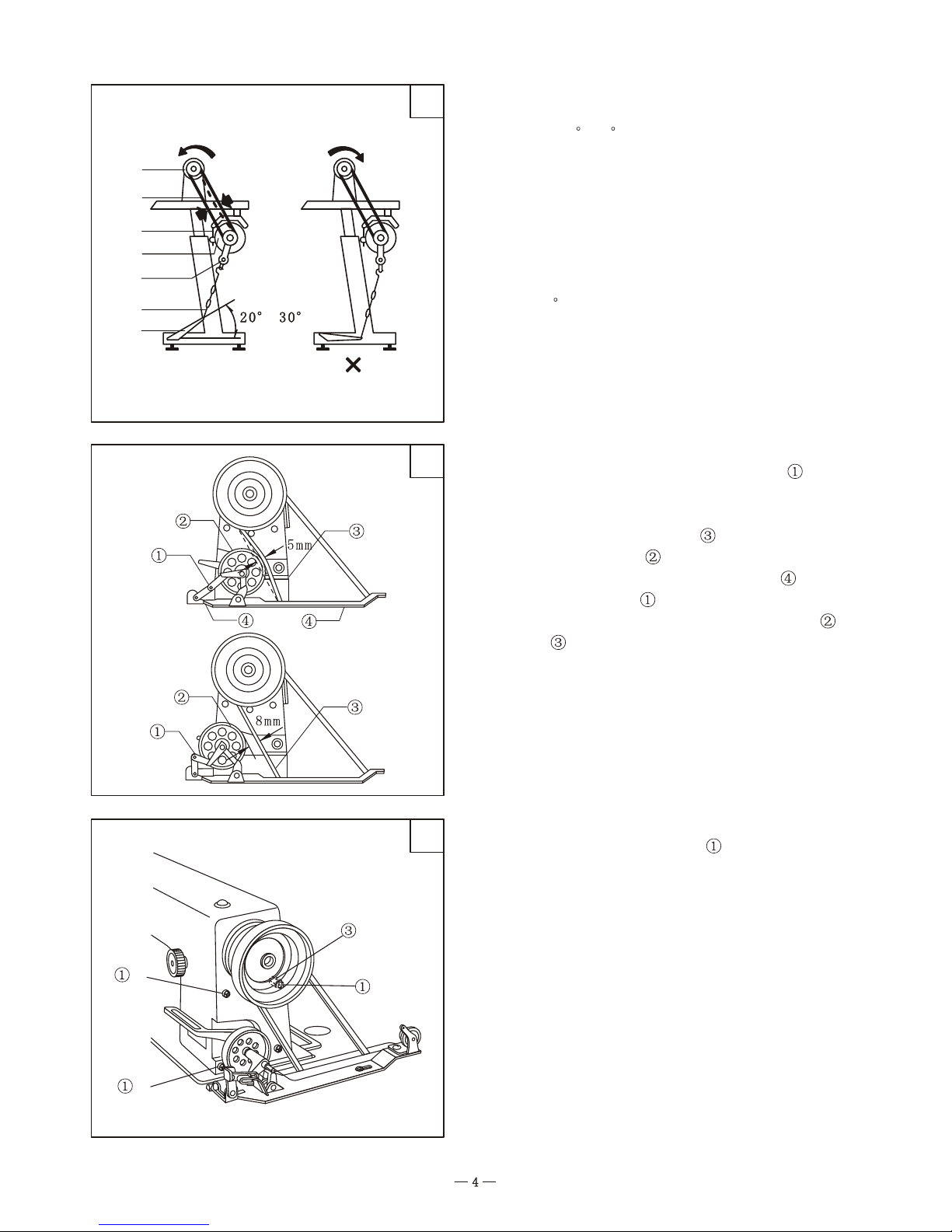
7. Installing the bobbin winder (Fig.8)
(1) Press the winding controlling lever to its
utmost position;
(2) Install the winder parallel with the belt hole in
the table, be sure that the belt
restores its original position,
be sure that the clearance between winder pulley
and belt is 8mm.
can be pressed to
5mm by winder pulley ;
(3) Fix the winder by two wooden screw ;
(4) When the lever
8. Installing the belt guard (Fig.9)
(1) Install the three screws on the machine
casting, please don't tighten the screws too tight.
10~1210~12
-a
-b
-c
9b9b
1010
1111
Long grooveLong groove
FrontalFrontal
5. Preparation before sewing
(2) Lay down the machine head and install the belt
guard in the screw bar and screw , tighen the
scr w -a.
(3) Raise the machine head and tighten the screw .
(4) Aim the gib of upper belt guard to the screw
e
-b, and cover the hand wheel by upper belt guard .
(5) Fix the upper belt guard by screw -b, -c
and .
(6) Install the lower belt guard and there should be
a overlap of 2 3mm with belt guard , tighten the two
screw .
(7) Insert the plate between belt guard and .
(8) Move the plate along the groove of belt guard
as far possible.
(9) Be sure that there should be not any clearance
between belt guard and plate .
(10) Tighten the two screws (refer to step ).
9. Oiling
(1) Please pull out the power plug to avoid hurting;
(2) lay down the machine head and fill the oil in the
oil pan till to the mark of HIGH
Notice:
Please use sewing oil 18#
Please replenish the oil when the level of oil
approaches to the mark of LOW
1. Installing the needle (Fig. 11)
(1) Turn the hand wheel to lift the needle bar to
its highest position;
(2) Loosen the needle set screw ;
(3) Make the needle groove to the left side of the
operator, then fully insert the needle shank until to
the bottom of the needle bar socket, tighten the set
screw .
-b
-c

1313
1212
1414
2. Uninstalling the bobbin case (Fig. 12)
(1) Turn the hand wheel to lift the needle above
the needl plate;
(2) Open the opener and uninstall the bobbin
case;
(3) Release the opener and uninstall the bobbin
3. Winding the bobbin thread (Fig. 13)
(1) Turn the power on;
(2) Install bobbin to bobbin winder shaft ,
push the lever down to the utmost position;
(3) Wind the thread several circles on the bobbin
(4) When the machine running, the bobbin will
be wound;
(5) After winding, the lever will be released
automatically, then uninstall the bobbin.
If the thread is wound unevenly. Loosen the
screw and move the bracket to the side which
the thread is little wound.
The winding amount can be adjusted by
screw
Increase the amount tighten
Decrease the amount loosen
Please be sure the optimum capacity of thread is
filled about 80% of bobbin outside diameter
4. Install the bobbin case (Fig. 14)
(1) Put the bobbin into the bobbin case as Fig 14
shown;
(2) Draw the bobbin thread through the slit and
pass it under the lace spring plate l
(3) Draw the bobbin thread out of the slit at the
top of lace spring plate;
(4) Draw the thread and confirm if the bobbin can
turn;
(5) Hold the opener and put the bobbin case in
the hook.
1515
About 50mm
55
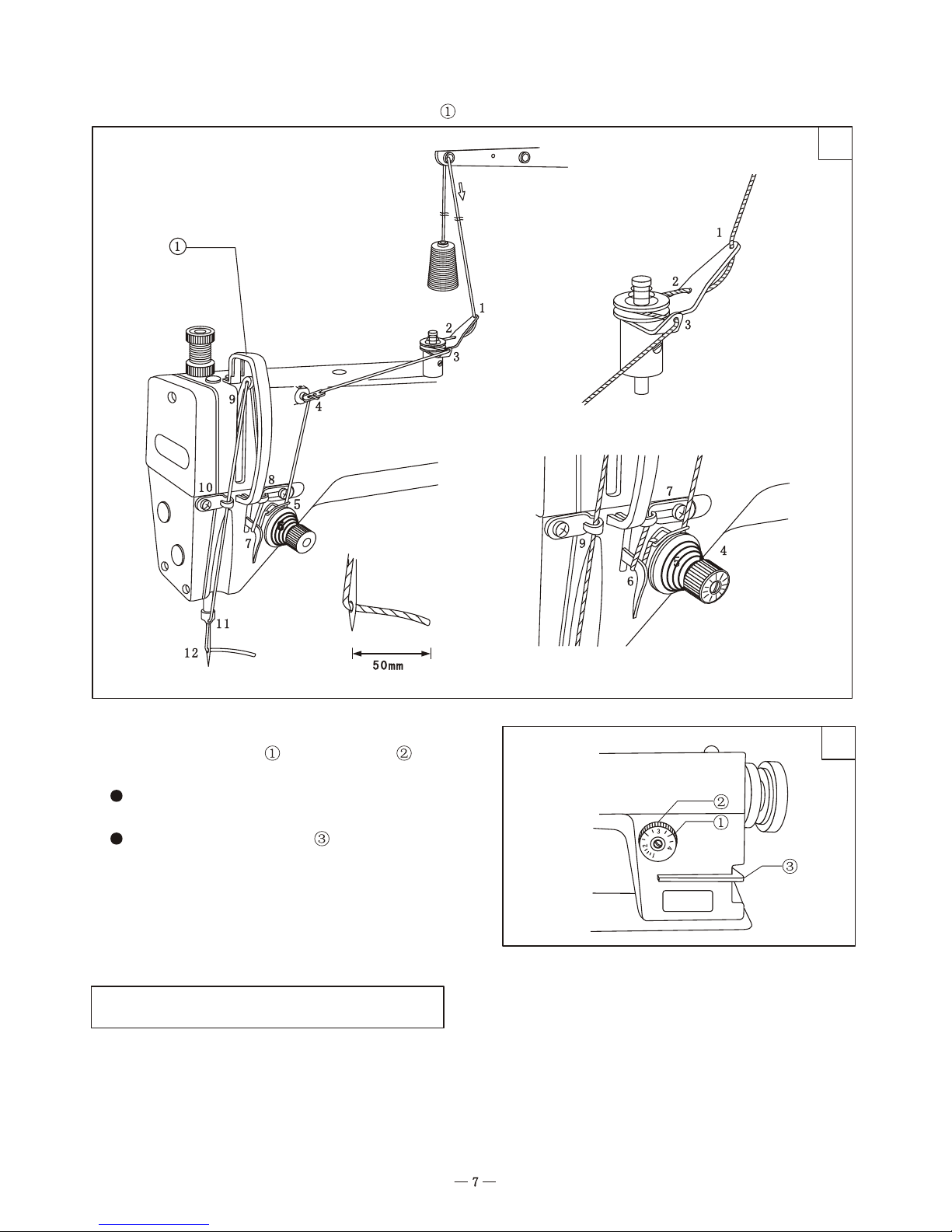
5. Threading the needle thread (Fig. 15)
Turn the hand wheel to lift the thread take-up lever to its highest position.
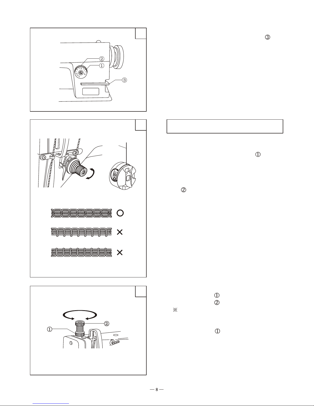
6. Adjusting the stitch length (Fig. 16)
(1) Turn the stitch dial to make the pin aim
at the number on the stitch dial.
The more big the number becomes, the more
long the stitch length is.
Please put the feed lever at the medium
position, then the dial can been turned easily.
6. Sewing
1. Sewing method
(1) Turn the switch on;
(2) The sewing begins after step the pedal
1616
1818
1919
Bobbin thread
Weaken
strengthen
WeakenWeaken
Weaken strengthen
7. Adjusting the tension of thread
2. Reverse sewing (Fig.17)
When sewing, press down the feed lever to
perform reverse sewing, release the lever, the
forward sewing is resumed.
1. Adjust the tension of thread (Fig. 18)
(1) Adjust the tension of needle thread
Lower the presser foot and adjust the nut as
shown in the Fig 18 (left)
(2) Adjust the tension of bobbin thread
Hold the tip of bobbin thread, the proper tension is
that the bobbin case can drops slowly, Adjust the
screw as shown in the Fig.
2. Adjust the pressure of presser foot (Fig. 19)
(1) Loosen the nut
.
(2) Turn the screw to adjust the pressure
Under the condition of without slippage, the
more small the pressure of presser foot, the more
good it is.
(3) Tighten the nut .
Strengthen
1717
 Loading...