

Page 1
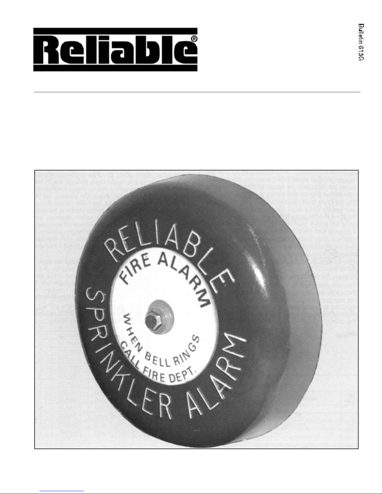
Model C
Mechanical
Sprinkler Alarm
Bulletin 613G
Instructions for
Installation, Operation, Care
and Maintenance
Listed by Underwriters Laboratories, Inc.
Approved by Factory Mutual Research
Corporation, and other fire insurance and
governmental agencies in the United
States and foreign countries.
The Reliable Automatic Sprinkler Co., Inc., 525 North MacQuesten Parkway, Mount Vernon, New York 10552
Page 2

Installation Instructions
The Model C Mechanical Sprinkler Alarm shall be
located as near the alarm (wet), dry or deluge valve as
practicable in order to avoid long runs or many fittings in
the piping. The total length of the pipe should not exceed
75 feet ( 22.9m ) nor shall the mechanical sprinkler alarm
be located over 20 feet (6.1m) above the valve. If
absolutely necessary to exceed 75 feet (22.9 m), the pipe
line to the mechanical sprinkler alarm shall be increased
one or more sizes to compensate for loss of pressure due
to hydraulic friction.
1.
Locate and cut hole in building wall for connecting ¾
(20mm) support pipe of appropriate length wall
thickness plus 1
″ (25mm).
2. Assemble the support pipe to the Wall Plate
(95106603) without removing the Gong (93806612)
and position this assembly on the outside wall with the
support pipe through the wall.
3. Remove the Body Cover (92106603), Cover Gasket
(93706602), and Pelton Wheel (97006603) from the
Body (91006603).
4. Place the Wall Support Washer (96906603) over the
support pipe as shown in the assembly drawing and
screw the Body onto the support pipe until the entire
assembly is aligned and secure to the wall.
5. Slip the Drive Shaft (96206603) thru the support pipe
and into the Drive Shaft Adapter (90086601). Rotate
the drive shaft to make sure it’s properly inserted (the
gong will alarm). Mark and cut the drive shaft where it
projects from the hub in the body.
6. With the drive shaft in place, make sure the Nylon
Bearing (90506603) is in the hub and insert the Pelton
Wheel through this onto the drive shaft. Spin the
Pelton Wheel to ensure that the assembly is free and
that the gong alarms.
7. Replace the Body Cover and Cover Gasket.
8. Connect alarm inlet to the alarm (wet), dry pipe or
deluge valve using galvanized or brass pipe of size
not less than ¾
″ (20mm). An approved ¾ ″ (20mm)
strainer is included for installation near the alarm outlet
of the alarm (wet), dry pipe or deluge valve. When a
retarding chamber is used in connection with an alarm
valve, the strainer shall be located at the outlet of the
retarding chamber unless the retarding chamber is
provided with an approved integral strainer in its outlet.
The piping to the mechanical alarm should be pitched
to allow proper drainage back through the strainer.
Alarm, dry pipe and deluge valve trimmings provide
the proper drain outlet. Refer to respective valve
bulletins for installation of trimmings.
″ (25mm) drain outlet should discharge into an
The 1
open drain.
″
No single mechanical alarm should be connected to
more than three sprinkler systems and they should be
located in the same fire area. A ¾
″ NPT (R¾) swing
check valve must be located in each alarm line near the
junction(s) going to the Mechanical Alarm. This will
assure that water flowing from the alarm port of the
opened Valve will go directly to the water motor. A hole
approximately
1
8″ (3.2mm) diameter should be drilled
through the clapper of each check valve near the center.
Operation
When an alarm (wet), dry pipe or deluge valve is
operated due to fire, water flows through the ¾
strainer, and ¾
″ (20mm) piping that connects the
mechanical sprinkler alarm to the valve. On entering the
mechanical sprinkler alarm inlet, the water passes
through the nozzle and impinges against the gong
producing a continuous piercing alarm. The water, after
impinging against the pelton wheel, drains through the 1
(25mm) drain outlet in the body housing.
The alarm continues to sound as long as water is
flowing through the sprinkler system. It may be shut off
by closing the alarm control valve located in the alarm line
connecting the mechanical sprinkler alarm with the alarm
(wet), dry pipe or deluge valve. Normally, the alarm
control valve must be sealed in the open position.
The Model C Mechanical Sprinkler Alarm is self setting
after each operation, eliminating the need of removing
cover plates, etc. to reset internal mechanisms.
″ (20mm)
″
2.
Page 3

Model C Mechanical Sprinkler Alarm
List of Model C Mechanical Sprinkler Alarm Parts
Item Part Number Description
1 91006603 Body 1
2 92106603 Body Cover 1
3 93706602 Cover Gasket 1
4 95606604 Body Cover & Adapter Screw 6
5 96906603 Wall Support washer 1
6 98604402 Clean-out Plug 1
7 97006603 Pelton Wheel 1
8 90506603 Bearing 2
9 96206603 Drive Shaft, 18
10 93806612 Gong 1
11 91106601 Gong Bolt 1
12 95106603 Wall Plate 1
13 90086601 Driver Shaft Adapter 1
14 73020063 Striker Assembly 1
15 78650200 Strainer, ¾
Should replacement parts be needed, use only genuine Reliable made parts.
When ordering, specify part number, name, model and serial number of the
unit.
″ 1
″ 24 Mesh (not shown) 1
Qty.
Req’d
3.
Page 4

Testing
1. Alarm Valve Installations
Refer to Alarm Valve Bulletins 407, 408 or 409.
The mechanical sprinkler alarm may be tested without
disturbing the alarm valve by opening the alarm test valve
located in the piping line connecting it to the alarm valve
inlet side.
To test the mechanical sprinkler alarm and the alarm
valve, open the 1
″ (25mm) inspector’s test connection.
This connection is usually located at the end or top line of
the system and its opening is equivalent to the fusing of
one automatic sprinkler.
2. Dry Pipe Valve Installations
Refer to Dry Pipe Valve Bulletins 350, 353 or 354.
To test the mechanical sprinkler alarm, open the alarm
test valve located in the piping connecting the sprinkler
alarm to the dry pipe valve inlet side.
Note: After testing, it is necessary to drain the water
from the alarm line – refer to the dry pipe valve inspection
and testing procedure.
3. Deluge valve installations
Refer to Deluge Valve Bulletins 501 or 503.
Test the mechanical sprinkler alarm by opening the
alarm test valve located in the piping line connecting the
sprinkler alarm to the deluge valve inlet side. After the
test is completed, push in on the plunger of the
mechanical ball drip valve until all water has drained from
the alarm line.
Maintenance
1. Sprinkler System – See NFPA 25 pamphlet –
Inspection Testing and Maintenance of Sprinkler
Systems.
2. Strainer – Refer to respective alarm, dry pipe or
deluge valve bulletins.
″ (20mm) strainer is located in the alarm line.
A ¾
Periodic removal and cleaning of the strainer will
eliminate accumulation of trash and scale which
can impair the flow of water, thereby preventing
proper operation of the sprinkler alarm.
3. Clean-out – The Clean-out Plug (98604402) in the
water motor should be removed periodically to
remove any accumulation of trash and scale that may
have passed through the strainer.
4. Bearings – These are nylon and do not require
lubrication.
Inspection
1. Check inside of gong for accumulation of trash,
nests, etc.
2. Be sure the gong bolt (91106601) is secure.
3.
Be sure that the ¾
Note: See “Maintenance.”
″ (20mm) strainer is clean.
4. False alarms – Refer to Alarm Valve Bulletins 407
or 408.
The equipment presented in this bulletin in accordance with the latest pertinent Standard of the Na tional Fire Protection Association, Factory Mutual Research
Corporation, or other similar organizations and also with the provisions of governmental codes or o rdinaire whenever applicable.
Products manufactured and distributed by Reliable have been protecting life and property for over 8 0 years, and are installed and serviced by the most highly
qualified and reputable sprinkler contractors located throughout the United States, Canada and fore ign countries.
Manufactured by
The Reliable Automatic Sprinkler Co., Inc.
800.431.1588 Sales Offices
800.848.6051 Sales Fax
914.668.3470 Corporate Offices
www.reliablesprinkler.com Internet Address
Revision lines indicate updated or new data.
E.G. Printed in U.S.A. 01/01 P/N 9999970060
 Loading...