

Page 1
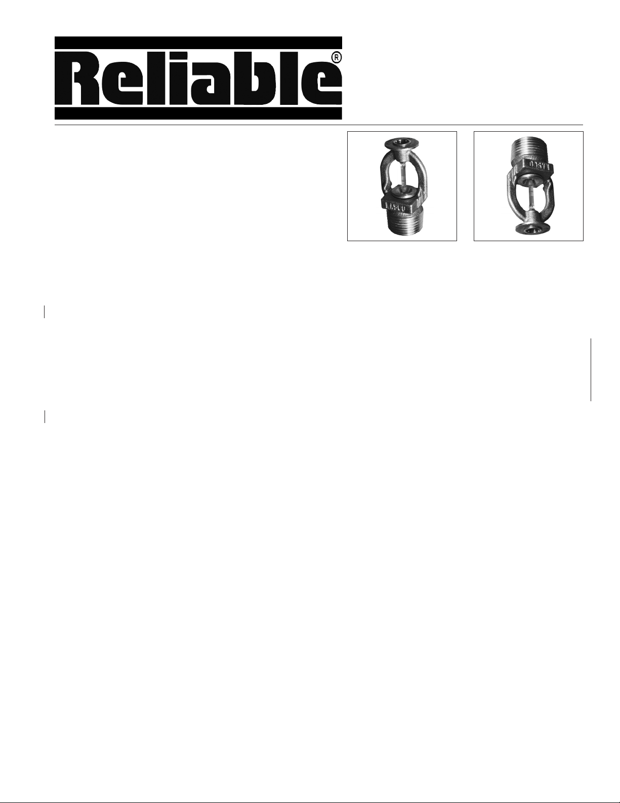
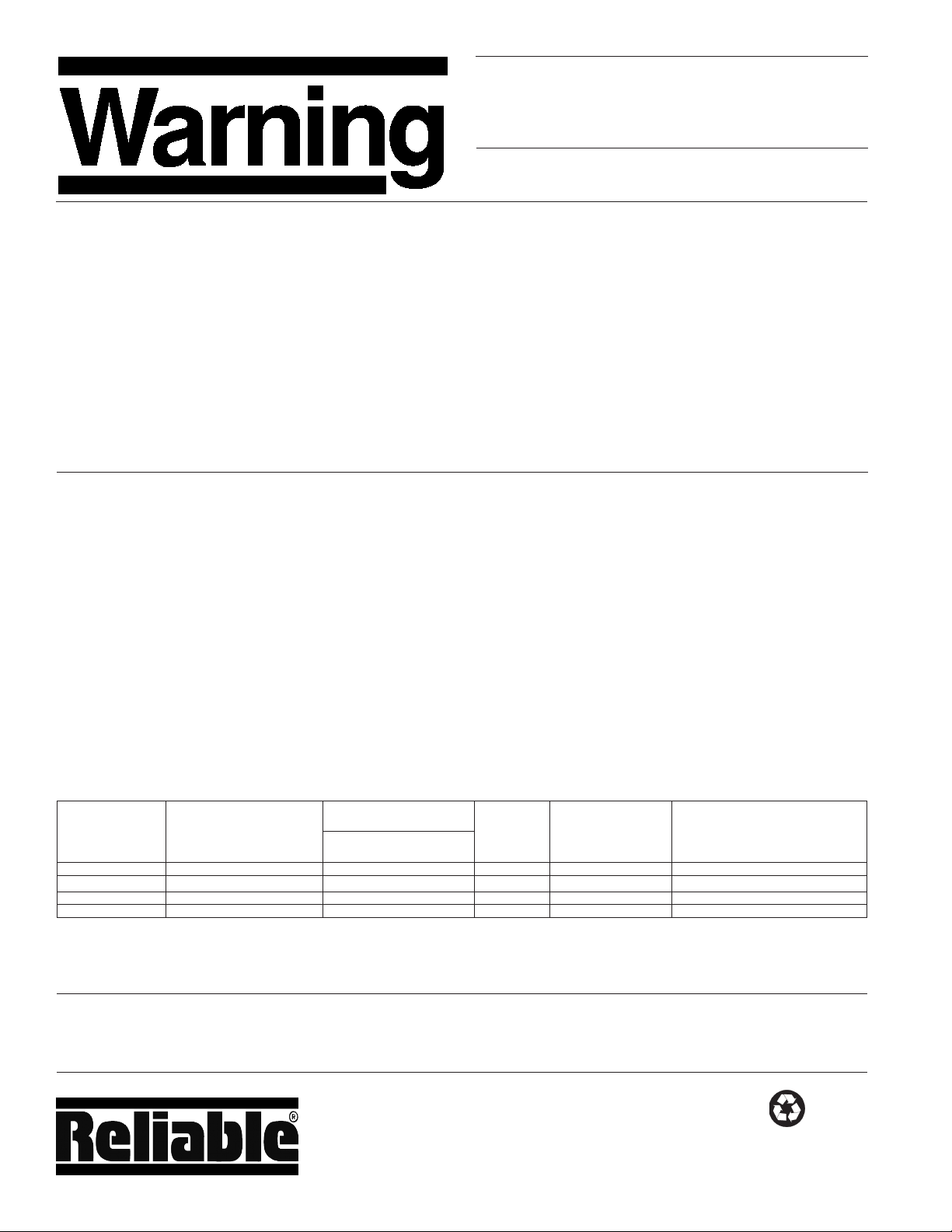
Pilot Line Detector (PLD)
Fixed Temperature Release
Features:
1. Fixed Temperature
Heat Responsive Detector
2. Installed Positions:
• Pendent
• Upright
3. Quick Response
4. Temperature Ratings:
135°F (57°C), 155°F (68°C),
175°F (79°C), and 200°F (93°C).
5. ½” (15 mm) Orifice with
½” NPT (R½) Thread
6. Die cast Brass Frame
7. Listed spacing
a. 40 ft x 40 ft (12 m x 12 m) for 155°F
(68°C), 175°F (79°C) and 200°F (93°C)
b. 50 ft x 50 ft (15 m x 15 m) for 135°F (57°C)
Product Description:
The Fixed Temperature Release (FTR) Pilot Line Detector (PLD) is designed to be used on wet or dry pilot line
release systems and trigger the operation of deluge systems, non-interlock preaction systems, single interlock
and double interlock systems. The FTR incorporates a
2.5 mm glass bulb with a Model F1 Sprinkler frame. It
is identified as a Fixed Temperature Release (FTR) to
differentiate it from a sprinkler. The FTR is made of die
cast brass and is available in various finishes. During fire
conditions the heat sensitive liquid in the bulb expands,
the bulb shatters, releasing the cap and spring assembly. This triggers the opening of the pilot line, releasing
the pressure (air, gas or water), causing the deluge or
preaction system valve to open and deliver water under
pressure to the system pipes.
Listings and Approvals
1. Listed with Underwriters Laboratories Inc. and UL
Certified for Canada (cULus)
2. NYC MEA 258-93-E
Bulletin 180 September 2018
F1-FTR
Fixed Temperature
Release
Technical Data
Thread Size: ½” NPT (R ½)
Orifice: Nominal ½” (15 mm)
Thermal Sensor: 2.5 mm glass bulb
Rated to 175 psi (12,1 bar) (12,066 kPa)
Frame – Die cast Brass
Seal – Teflon Coated
Standard Finishes –
Brass, Chrome plated or Polyester White
Factory tested Hydrostatically to 500 psi (34,5 bar)
(34,475 kPa).
(1)
Polyester White is UL and ULC Listed corrosion resistant.
Installation
The F1-FTR must be installed in accordance with NFPA13 specifications and after the pilot line system piping is in
place (to prevent possible damage to FTR). Before installing be sure the F1-FTR has the appropriate temperature
rating which should be lower than the temperature rating
of system nozzles or sprinklers. Apply a small amount of
pipe joint compound to the male thread when installing
FTR.
Install the F1-FTR into the pilot line piping using only the
special Model W2 Wrench. (See Bulletin 205).
The F1-FTR must be handled carefully, and stored in a
cool, dry place in the original container. Never install a
F1-FTR that has been dropped or damaged in anyway. Do
not install the F1-FTR if the bulb is cracked or seems low
on liquid. If the F1-FTR is not returned to Reliable it should
be destroyed. Never install a F1-FTR that has been exposed to a temperature in excess of the allowed ambient
temperature.
The F1-FTR can be installed in any position; however, in
locations where the pilot line system is exposed to freezing conditions install them in the upright position only. Wet
pilot lines must be installed where there is adequate heat
to avoid possible freezing. An F1-FTR pilot line that may
be subject to mechanical damage must be protected by
the appropriate sprinkler guard (see Bulletin 208) for the
F1 Model.
(1)
.
Bulletin 180 September 2018
The Reliable Automatic Sprinkler Co., Inc., 103 Fairview Park Drive, Elmsford, New York 10523
Page 2
Important Precautions To Follow
1. Detectors are to be installed in accordance with the latest published
standards of the National Fire Protection Association, other similar
organizations and with the provisions of governmental codes or ordinances whenever applicable.
2. Use only the Model W2 wrench to install detector. Any other wrench
may damage the detector.
3. Never install a detector after it has been dropped or damaged in
any way. These detectors should be destroyed.
4. Never Install detectors in the fittings until the piping is in place on
the ceiling. Detectors are liable to be damaged if installed when the
lines are made up at the bench or on the floor.
5. Never attach wiring, ropes or fixtures to a detector or piping system.
Continued from page 1.
Any alteration to the detectors after they leave the factory
including, but not limited to, painting, plating coating or
other modification may render the detectors inoperative
and will nullify all approvals.
6. Use guards on all detectors subject to injury by moving objects.
7. If pipe compound is used, apply to detector pipe thread only.
8. Store detectors in a cool, dry place. Prior to installation, detectors
should be maintained in original cartons and packaging until used
to minimize potential damage that would cause improper operations or non-operation.
9. NEVER APPLY PAINT OR ANY OTHER COATING TO DETECTOR.
10. Removal of paint or other coatings with solvents is not permissible.
11. When installing detector in plastic pipe, excess solvent cement
used during pipe installation must not become an obstruction inside inlet. Install detector into the sprinkler fittings only after all piping
is in place and solvent cement at each drop joint has cured at least
30 minutes.
After installation the entire pilot line system must be
pressure-tested to ensure proper operation, meeting the
required application standards, verifying that no unit was
damaged in shipping on installation, and that all detectors
are securely tightened. If a thread leak is noticed the unit
must be removed, new pipe joint compound applied and
then reinstalled.
Maintenance
Fire protection systems should be inspected in accordance with NFPA 25 guidance. Keeping the fire protection
system in properly, maintained conditions is the responsibility of the owner. Model F1-FTR must be inspected
regularly for corrosion, mechanical damage, paint etc.
Do not clean them with soap and water, ammonia or any
other cleaning fluid. Remove dust by using a soft brush or
Release
Temperature
Classification
Ordinary 135°F (57°C) 100°F (38°C) Orange None 50 ft x 50 ft (15 m x 15 m)
Ordinary 155°F (68°C) 100°F (38°C) Red None 40 ft x 40 ft (12 m x 12 m)
Intermediate 175°F (79°C) 150°F (65°C) Yellow White 40 ft x 40 ft (12 m x 12 m)
Intermediate 200°F (93°C) 150°F (65°C) Green White 40 ft x 40 ft (12 m x 12 m)
(1)
Based on NFPA-13. Other limits may apply depending on fire loading, sprinkler location, and other Authority-Having-Jurisdiction requirements.
Refer to specific installation standards.
(2)
Listed spacings are for smooth, flat, horizontal ceilings. Installation must comply with NFPA 13; NFPA 15, 3-5.2 & NFPA 72, 2-2 and Appendix B
Nominal Temperature
Rating of Release
(Fusing Point)
Ceiling Temperature
at Release
Max. Recommended
Ambient Temp.
gentle vacuuming. Remove any detectors that have been
painted (other than factory applied) or damaged in any
way. A stock of spare detectors should be maintained to
allow quick replacement of damaged or inoperable units.
Prior to installation, all detectors should be maintained in
the original cartons until used. This minimizes the potential for improper or non-operation. Systems subjected to
fire must be returned to service as soon as possible. The
entire system must be inspected for damage and repaired
or replaced as necessary. Sprinklers and fixed temperature releases that have been exposed to corrosive products of combustion or high ambient temperatures, but
have not been operated, should be replaced. Refer to the
Authority Having Jurisdiction for minimum replacement requirements.
Bulb
(1)
Color
Temperature
Rating Color
Code
Listed Spacing
(2)
The equipment presented in this bulletin is to be installed in accordance with the latest published Standards of the National Fire Protection Association, Factory
Mutual Research Corporation, or other similar organizations and also with the provisions of governmental codes or ordinances whenever applicable.
Products manufactured and distributed by Reliable have been protecting life and property for over 90 years, and are installed and serviced by the most highly
qualified and reputable sprinkler contractors located throughout the United States, Canada and foreign countries.
Manufactured by
The Reliable Automatic Sprinkler Co., Inc.
(800) 431-1588 Sales Offices
(800) 848-6051 Sales Fax
(914) 829-2042 Corporate Offices
www.reliablesprinkler.com Internet Address
Revision lines indicate updated or new data.
EG. Printed in U.S.A. 09/18
Recycled
Paper
P/N 9999970218
 Loading...