

Reliable F1 Installation Manual
Bulletin 140 Rev. J
Model F1 Res and
RFC Residential Sprinkler
Design and Installation Guide
Bulletin 140 Rev. J
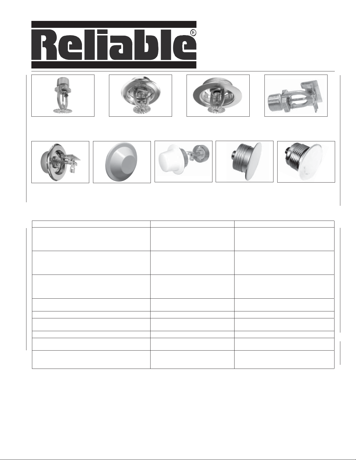
F1 Res 30/30LL,
49/49LL, 58/58LL & 76
Pendent
F1 Res 44/44LL
& 58/58LL
F1 Res 30/30LL,
49/49LL, 58/58LL & 76
Recessed HSW/F2
Sprinkler Model and Type Sprinkler Identifi cation Number Reliable Bulletin Number
F1 Res 30/30LL Pendent
F1 Res 30/30LL Recessed Pendent/F1
F1 Res 30/30LL Recessed Pendent/FP
F1 Res 30/30LL Concealed Pendent/CCP
F1 Res 49/49LL Pendent
F1 Res 49/49LL Recessed Pendent/F1
F1 Res 49/49LL Recessed Pendent/FP
F1 Res 49/49LL Concealed Pendent/CCP
F1 Res 58/58LL Pendent
F1 Res 58/58LL Recessed Pendent/F1
F1 Res 58/58LL Recessed Pendent/FP
F1 Res 58/58LL Concealed Pendent/CCP
RFC 30/30LL, 43/43LL & 49/49LL Concealed Pendent
RFC 56 Concealed Pendent RA0914 Horizontal Ceilings – 009
F1 Res 44/44LL Horizontal Sidewall
F1 Res 44/44LL Recessed Horizontal Sidewall
F1 Res 44/44LL SWC Concealed Horizontal Sidewall R3531, RA3331 Horizontal Ceilings – 135,033
F1 Res 58/58LL Horizontal Sidewall
F1 Res 58/58LL Recessed Horizontal Sidewall/F2
F1 Res 76 PendentF1 Res 76 Recessed Pendent/F1
F1 Res 76 Recessed Pendent/FP
F1 Res 76 Concealed Pendent/CCP
F1 Res 30/30LL,
49/49LL, 58/58LL & 76
Recessed Pendent / F1
F1 Res 44/44LL
SWC
CCP Pendent
R3516, RA3316
R3513, RA3313 Horizontal Ceilings - 135, 033
RA0611, RA0612, RA0616, RA3211,
RA3212, RA3216
R3531, RA3331
R3533, RA3335 Horizontal Ceilings - 135, 033
F1 Res 30/30LL,
49/49LL, 58/58LL & 76
Recessed Pendent / FP
RFC 30/30LL,
43/43LL, 49/49LL
R3511
RA3311
R7618 Horizontal Ceilings – 135, 176
Horizontal Ceilings – 135, 033
Horizontal Ceilings – 135, 033
Horizontal Ceilings – 006, 032
Horizontal Ceilings – 135, 033
F1 Res 44/44LL
& 58/58LL
HSW
RFC 56
Sloped Ceilings - 035
Sloped Ceilings – 035
Sloped Ceilings - 035
Table A
Model F1 Res and Model RFC Residential Sprinklers
The Reliable Automatic Sprinkler Co., Inc., 103 Fairview Park Drive, Elmsford, New York 10523

General
Reliable residential sprinklers utilize a fast response
thermal element and are intended for use in only wetpipe residential sprinkler systems designed in accordance with the following NFPA standards: NFPA 13D,
Installation of Sprinkler Systems for One-and Two-Family
Dwellings and Manufactured Homes; NFPA 13R, Installation of Sprinkler Systems for Residential Occupancies Up to and Including Four Stories in Height; and for
the residential portions of any occupancy as permitted
by NFPA 13, Installation of Sprinkler Systems. Fast response and high wall wetting characteristics of residential sprinklers improve life safety by maintaining a tenable environment, providing escape time for occupants.
NFPA 13D is appropriate for protection against fire
hazards only in one-and two-family dwellings and manufactured homes. Residential portions of any other type
of building or occupancy should be protected with residential sprinklers in accordance with NFPA 13, or in accordance with NFPA 13R. NFPA 13R is appropriate for
use as an option to NFPA 13 only in those residential
occupancies up to and including four stories in height.
Where buildings are greater than four stories in height,
or where buildings are of mixed use where residential is
not the predominant occupancy, protect residential portions of such buildings with residential or quick response
sprinklers in accordance with NFPA 13.
This document provides design guidelines for the
Model F1/Res and RFC Residential Sprinklers shown in
Table A, which are cULus Listed to provide a minimum
density of 0.05 gpm/ft
mentioned standards, manufacturer’s instructions, and
technical bulletins. Where documentation for residential
sprinkler systems does not exist for particular applications, information based on NFPA 13 is used.
Residential fire sprinkler systems should only be designed and installed by competent individuals trained
and experienced with automatic sprinkler system design and installation. Several criteria may apply to a
given installation and the designer and/or installer must
be familiar with the applicable codes, standards, and
guidelines governing such an installation. The Reliable
Model F1/Res and RFC residential sprinklers described
herein must be installed and maintained in compliance
with this document manufacturer’s recommendations,
with the latest published standards of the National Fire
Protection Association (NFPA), and with any additional
local jurisdictional requirements. Failure to comply may
result in the impairment of sprinkler integrity and proper
operation. Because of the various features of residential
type architecture, there will be some compartment designs which cannot be fully sprinklered in accordance
with the recommendations of NFPA 13, 13D, or 13R. In
these instances, consult the Authority Having Jurisdiction for guidance and approval.
2
, in accordance with the above-
The owner is responsible for maintaining their fire protection system and associated devices in proper operating condition. Refer to NFPA 25, Inspection, Testing,
and Maintenance of Water-Based Fire Protection Systems, for guidance on testing and maintenance of automatic sprinkler systems.
Approvals
All Reliable residential sprinklers have been designed
and tested in accordance with the latest Edition of Underwriters Laboratories (UL) 1626, Standard for Residential
Sprinklers for Fire Protection Service. Typically, they are
cULus Listed for installation under smooth, flat ceilings
of unobstructed construction, unless otherwise noted
in the specific listings, with specific approved spacing,
flows, and pressures. Reliable residential sprinklers are
cULus Listed for installation on both horizontal ceilings
with a maximum slope of 2/12 (9.4°) pitch, and sloped
ceilings (where applicable) having maximum slopes of
4/12 (18.4°) and 8/12 (33.7°) pitch. The design criteria
for residential sprinklers contained in the current NFPA
13D, 13R, and 13 Standards must be followed except
as modified by the individual UL 1626 listing information, the information in the Reliable residential sprinkler
bulletins, and this installation guide. The Authority Having Jurisdiction (AHJ) must make final approval for all
residential sprinkler installations for compliance with all
applicable codes, standards, and jurisdictional requirements.
One of the most important revisions of the Third Edition of UL 1626 is the new minimum density requirement
for residential sprinklers manufactured after July 12,
2002. When establishing a minimum cULus Listed flow
rate, the manufacturer must use a minimum discharge
rate over the specified coverage area corresponding
to a 0.05 gpm/ft2 density. In some cases, however, to
successfully pass the UL 1626 fire tests, the UL Listed
flow rate may be greater than the calculated 0.05 gpm/
ft2 density. Increased flow rates for horizontal sidewall
type sprinklers, which exceed this minimum density, is
common. Because this minimum density is a listing requirement, the use of residential sprinklers meeting this
criterion is applicable to all editions of NFPA 13, 13R and
13D. The design criteria for residential sprinklers contained in the current NFPA Standards must be followed
except as modified by the individual cULus Listing information provided in the technical bulletins referenced in
Table A.
2.

Defi nitions
The following NFPA definitions are applicable to the
terms used in this installation guide. Where terms are
not included, refer to NFPA 13, NFPA 13D and NFPA
13R for official definitions:
Residential Sprinkler – A type of fast-response sprinkler that has a thermal element with an RTI of 50 (m-s)
½ or less, has been specifically tested for its ability to
enhance survivability in the room of fire origin and listed
for use in the protection of dwelling units. Residential
sprinklers posses a fast response thermal element and
produce a spray pattern that discharges water higher
on the wall than a standard spray sprinkler.
Dwelling – Any building that contains not more than
one or two dwelling units intended to be used, rented,
leased, let or hired out to be occupied or that are occupied for habitation purposes.
Dwelling Unit – One or more rooms, arranged for the
use of one or more individuals living together, as in a
single housekeeping unit, that normally have cooking,
living, sanitary, and sleeping facilities. Dwelling units
include hotel rooms, dormitory rooms, condominiums,
apartments, and similar living units.
Compartment – A compartment is a space completely
enclosed by walls and a ceiling. The compartment enclosure is permitted to have openings (in walls) to an
adjoining space, provided that soffits or lintels along the
ceiling over the compartment opening has a minimum
depth of 8 in. (203mm) from the ceiling. In other words,
areas such as hallways, stairwells, and rooms must be
separated by beams, lintels or soffits 8 or more inches in
depth to be considered single compartments.
Obstructed Construction – Panel construction and
other construction where beams, trusses, or other members impede heat flow or water distribution in a manner
that materially affects the ability of sprinklers to control
or suppress a fire. See NFPA 13 Appendix for detailed
explanations of this type of construction.
Unobstructed Construction – Construction where
beams, trusses, or other members do not impede heat
flow or water distribution in a manner that materially affects the ability of sprinklers to control or suppress a
fire. This type of construction has the following features:
(1) horizontal structural members that are not solid; (2)
openings of the structural members are at least 70% of
the cross sectional area; (3) depth of the structural members do not exceed the least dimension of the openings;
or (4) the spacing of structural members exceeds 7.5
feet on center. See NFPA 13 Appendix for detailed explanations of this type of construction.
Flat Ceiling – a continuous ceiling in a single plane.
Smooth Ceiling – A continuous ceiling free from signifi-
cant irregularities, lumps or indentations.
Horizontal Ceiling – A ceiling that does not exceed a
slope of 2/12 pitch (slope of 16.7% or 9.4°).
Sloped Ceiling – A ceiling exceeding a maximum slope
of 2/12 (9.4°) pitch.
Installation Considerations
Residential sprinklers utilizing a glass bulb thermal element have orange protective caps and straps to provide
temporary protection to the frangible glass bulb during
shipping and installation.
a. Do not install any bulb type sprinkler if the bulb is
cracked or there is liquid missing from the bulb.
While holding the sprinkler in the horizontal position, a small air bubble having an approximate
diameter of 1/16” should be visible.
b. The sprinkler is designed for installation with the
protective strap in place using the appropriate
sprinkler wrench.
c. Sprinklers that are dropped during the installa-
tion process or that are installed on piping other
than that in accordance with item “a” shall be replaced, including sprinklers with protective caps
or straps.
d. Protective caps and straps shall be removed only
using means in accordance with the manufacturer’s installation instructions. They are not to be
left on the sprinkler after the sprinkler system is
placed in service.
e. Protective caps and straps shall be removed only
when water supply is made available to the sprinkler for the purposes of fire protection and placed
in service.
f. A leak-tight ½” NPT sprinkler joint should be ob-
tained with a maximum torque of 14 ft-lbs to 21
ft-lbs. (approximately 2 turns past hand tight. Do
not over tighten). Higher levels of torque may distort the sprinkler inlet or bend the frame, causing
leakage or impairment of the sprinkler.
Where applicable, escutcheon plates must be installed. Absence of an escutcheon plate, where there is
an annular space between the ceiling and the sprinkler,
may delay sprinkler operation in the event of a fire.
Never introduce any leak stopping additives to any fire
sprinkler system.
3.

Residential sprinklers must be installed with the manufacturer’s specified sprinkler wrench. Channel locks,
crescent wrenches or anything other than the proper
sprinkler wrench shall not be used.
Installing sprinklers in CPVC and copper piping systems require special considerations. Never install the
sprinkler into the reducing fitting prior to attaching the
reducing fitting to the system piping. When installing
residential sprinklers or commercial sprinklers in a CPVC
piping system, sprinklers must be installed only after the
reducing fitting has been installed and the CPVC manufacturer’s setting time for the primer and/or cement has
passed. This is to ensure that the cement does not accumulate within the sprinkler. In copper piping systems,
sprinklers must be installed only after the inside of the
sprinkler drop and associated fittings have been wirebrushed to remove any residual flux.. Residual flux can
cause corrosion. Both of these conditions can impair
and prevent proper sprinkler operation.
System Design Criteria
Permitted Sprinklers for Residential Sprinkler Systems
For NFPA 13D and 13R sprinkler systems, only listed
residential sprinklers shall be used, with the following
exceptions:
1. Listed standard dry-pendent or dry sidewall sprinklers
shall be permitted to be extended into unheated areas
not intended for living purposes.
2. Quick-response sprinklers shall be permitted to be used
in mechanical closets.
3. For NFPA 13R systems, listed quick-response sprinklers
shall be permitted to be installed in dwelling units meeting the definition of a compartment where no more than
four (4) sprinklers are located within the dwelling unit.
Non-residential sprinklers are to be installed in accordance with the criteria specified by NFPA 13.
Residential Sprinkler Positioning and Spacing Requirements
When locating residential sprinklers, consideration
must be given to sensitivity, sprinkler spacing, obstructions to discharge, temperature rating, and proximity to
heat sources.
Sprinkler Sensitivity - Deflector Positioning
Residential pendent sprinklers not listed with specific
positioning criteria must be positioned so that the deflectors are within 1 in. to 4 in. (25.4 mm to 102 mm) from the
ceiling. On flat, horizontal ceilings, Reliable Model F1
Res 49 pendent and recessed pendent sprinklers may
also be positioned with the deflector 4” to 8” (102 mm to
203 mm) from the ceiling, in accordance with the listed
flows and pressures shown in Bulletin 135. If located in
closets, it is permitted to install pendent sprinklers so that
the deflector is within 12 inches (305 mm) of the ceiling.
Residential sidewall sprinklers that have not been listed
with specific positioning criteria must be positioned so
that the deflectors are within 4 in. to 6 in. (102 mm to 152
mm) from the ceiling. Install sidewall sprinklers having
listed positioning criteria in accordance with their listing.
Under both horizontal and sloped ceilings, always align
sprinkler deflectors so that the deflector is parallel with
the plane of the ceiling surface.
Sprinkler Spacing Under Horizontal Ceilings
Several maximum coverage areas are used for residential sprinklers in accordance with minimum listed
flows and pressures. The area of coverage must be
equal to or greater than both the length and width of the
hazard area. Residential sprinklers must be located not
more than half the listed spacing nor less than 4” (102
mm) from walls. Adjacent sprinklers must be located no
farther apart than the listed spacing; the minimum distance to prevent cold soldering, unless otherwise specified, is 8 feet (2.44 m).
When selecting an area of coverage, the suggested
practice is to select one that can be adequately supplied
by the available water supply, allowing for the installation of as few sprinklers as possible while observing all
guidelines pertaining to obstructions and spacing. After selection of an area of coverage, sprinklers must be
spaced according to the criteria set forth in the NFPA
standards and this document.
Sprinkler Spacing Under Sloped Ceilings
For installation under sloped ceilings, several maximum coverage areas are also provided, but at different
minimum flows and pressures than those for horizontal
ceilings. The spacing of sprinklers is measured along
the slope when determining the distance off of walls and
between sprinklers. Residential sprinklers may be located no more than ½ the listed spacing nor less than 4”
(102 mm) from the peak of the sloped ceiling. Residential sprinklers located at the highest elevation must not
be located more than 3 feet (0.9 m) measured vertically
down from the peak. Refer to Reliable Bulletin 035 for
listed coverage areas, flow and pressure requirements,
and positioning criteria for residential sprinklers installed
under sloped ceilings.
Obstruction to Water Distribution
Refer to Figures 1 through 13 for the location of sprinklers relative to obstructions. The discharge from residential sprinklers is directed radially outward and downward from the sprinkler. Sprinklers must be located
such that there will not be any spaces shielded from
distribution by walls, dividing partitions, or other dwell-
4.
ing construction features. If the sprinkler water distribution pattern is obstructed, the obstruction is to be considered the maximum distance of coverage for a given
sprinkler. Additional sprinklers beyond the obstruction
may be necessary unless the obstruction criteria contained herein can be met. Consult the appropriate NFPA
standard and/or the AHJ for guidance regarding these
situations.
Reliable flat plate concealed sprinklers, the Models RFC30 (30LL), RFC43 (43LL), RFC49 (49LL) and
RFC56, utilize a drop-down style deflector. The distance
the deflector drops below the ceiling is needed when
determining the position of the deflector above the bottom of an obstruction. These distance are as follows:
• Nonadjusted (cover plate flush to cup) - 7/8” (22mm)
• At full (1/2”) adjustment - 3/8” (9.5mm)
Continuous and Noncontinuous Obstructions
A minimum distance is required to be maintained between sprinklers and continuous obstructions, such as
beams, soffits, and long horizontal light fixtures. See Figures 1, 2, 4, 5, 6, 7 and/or 13.
A minimum distance is also required to be maintained
between sprinklers and noncontinuous obstructions,
such as ceiling fans and certain light fixtures. The ceiling fan motor housing is the primary element that can
obstruct the sprinkler discharge pattern. Testing has
demonstrated that no adverse effects occur as a result
of the ceiling fan’s blade rotation in either direction.
With regards to location of sprinklers near light fixtures,
there are two considerations; the amount of heat the
light gives off and the light fixture as an obstruction. The
minimum distance of a sprinkler relative to the light as a
heat source is given in Table B. If the light is also an obstruction, then the obstruction criteria must be applied,
relative to the minimum distance required from Table B.
For noncontinuous obstructions, apply the “four times
rule” as provided in NFPA 13 where it is determined that
the sprinkler can spray to at least two sides of the obstruction, either over and under or around the obstruction on both sides. Sprinklers shall be positioned away
from the obstruction a minimum distance of four times
the maximum dimension of the obstruction. The maximum clear distance required shall be 36”(914mm).
Temperature Ratings
Ordinary temperature rated sprinklers (135°F [57°C],
155°F [57°C]) are only permitted for installation where
the maximum ambient ceiling temperature will not exceed 100°F (38°C). Where ambient ceiling temperatures are expected to exceed 100°F (38°C), use intermediate temperature-rated residential sprinklers (175°F
[79°C]), which can be exposed to a maximum ambient
temperature of 150°F (66°C). The following practices
apply, unless higher expected ambient temperatures require a higher temperature rated sprinkler:
1. Sprinklers under glass or plastic skylights exposed
to direct rays of the sun shall be of the intermediate
temperature classification.
2. Sprinklers in an unventilated concealed space under insulated roof or in an unventilated attic shall be
of the intermediate temperature classification.
3. Residential sprinklers must be located so as to prevent inadvertent operation due to exposure to normal heat sources. Sprinklers must be positioned a
sufficient distance away from heat sources such as
fireplaces, ovens, kitchen ranges, hot water pipes,
water heaters, furnaces and associated duct work,
and light fixtures. The following minimum distances in accordance with NFPA 13D and 13R must be
maintained as indicated in Table B.
Table B – Minimum Distances for Ordinary and
Intermediate Residential Sprinklers Relative to Specifi c Heat Sources
Minimum Distance
from Edge of Source
Heat Source
Side of open or Recessed fireplace 36 (914) 12 (305)
Front of recessed fireplace 60 (1524) 36 (914)
Coal or wood-burning stove 42 (1067) 12 (305)
Kitchen range 18 (457) 9 (229)
Wall oven 18 (457) 9 (229)
Hot air flues 18 (457) 9 (229)
Uninsulated heat ducts 18 (457) 9 (229)
Uninsulated hot water pipes 12 (305) 6 (152)
Side of ceiling or wall-mounted hot air diffusers 24 (607) 12 (305)
Front of wall-mounted hot air diffusers 36 (914) 18 (457)
Hot water heater or furnace 6 (152) 3 (76)
Light Fixture
0 W – 250 W
250 W – 499 W
to Ordinary Temperature Sprinkler
(135°F or 155°F)
in. (mm) in. (mm)
6 (152)
12 (305)
from Edge of Source to Intermediate
Minimum Distance
Temperature Sprinkler
(175°F)
3 (76)
6 (152)
5.

Hydraulic Design Requirements
Reliable residential sprinkler listings indicate minimum
flow rates for each specified coverage area. Hydraulic calculations are required to verify adequate water
supply at the hydraulically most remote single sprinkler
operating at the minimum flow and pressure listed for
single sprinkler operation. Where a compartment has
more than one sprinkler, multiple sprinkler calculations
are required, and each sprinkler within the design area
must be calculated using the flow rates corresponding
to its area of coverage. No reduction in minimum flow
requirements is provided for flowing multiple sprinklers.
More design sprinklers may need to be calculated than
the minimum stated by the NFPA standards where unusual conditions may result in more sprinklers operating.
These conditions include sloped ceilings having a pitch
greater than 8/12 (33.7°) or beamed ceilings qualifying as obstructed construction, as defined by NFPA 13.
Consult with the AHJ regarding the number of “design
sprinklers” for these types of applications..
NFPA 13D
The number of design sprinklers under flat, smooth,
horizontal ceilings shall include all sprinklers within a
compartment, up to a maximum of two (2) sprinklers,
that requires the greatest hydraulic demand. The cULus
Listed specific coverage criteria for systems designed
to NFPA 13R are given in the technical bulletins referenced in Table A, as a function of the maximum allowable coverage area and temperature rating. For actual
coverage areas less than or between those indicated in
the respective bulletin, it is necessary to use the minimum required flow for the next largest area, as shown
above.
For example, assuming the use of a pendent sprinkler,
for an actual coverage area of 12 ft x 14 ft (3.7 m x 4.2
m), the specific coverage criteria for a 14 ft x 14 ft (4.2
m x 4.2 m ) coverage area must be used. For an actual
coverage area of 15 ft x 15 ft (4.6 m x 4.6 m), the specific
coverage criteria for a 16 ft x 16 ft (4.9 m x 4.9 m) coverage area must be used.
NFPA 13R
The number of design sprinklers under flat, smooth,
horizontal ceilings shall include all sprinklers within a
compartment, up to a maximum of four (4) sprinklers,
that requires the greatest hydraulic demand. The cULus
Listed specific coverage criteria for systems designed
to NFPA 13R are given in the technical bulletins referenced in Table A, as a function of the maximum allowable coverage area and temperature rating. For actual
coverage areas less than or between those indicated in
the respective bulletin, it is necessary to use the minimum required flow for the next largest area, as shown
above.
NFPA 13
For residential sprinkler systems designed to NFPA 13,
a minimum density of 0.1 gpm/ft2 must be provided over
the “design area” that includes the four (4) hydraulically
most demanding sprinklers for the actual coverage areas being protected by the 4 sprinklers. The minimum
required discharge from each of the four most hydraulically demanding sprinklers shall be the greater of the
following:
1. The flow rates given in the Reliable Residential
Sprinkler Technical Bulletins referenced in Table A
for NFPA 13D and 13R as a function of temperature
rating and maximum allowable coverage area (for
actual coverage areas less than or between those
indicated in the respective technical bulletin, it is
required to use the minimum required flow for the
next largest coverage area); or
2. A minimum discharge density of 0.1 gpm/ft2 applied over the “design area” consisting of the four
most hydraulically demanding sprinklers for the
actual coverage areas being protected by the four
sprinklers. The maximum dimension of the actual coverage area cannot be any greater than the
maximum coverage area indicated in the technical
bulletins referenced in Table A.
Design Note: Using the As = S x L method to de-
termine the sprinkler protection area of coverage
in accordance with NFPA 13, apply the 0.1 gpm/ft
density to this area to determine the minimum required flow. Compare this flow to the minimum 0.05
gpm/ft2 cULus Listed flow for the appropriate coverage area in the technical bulletin for the specific
residential sprinkler. If the flow stated in the technical bulletin is less than the calculated 0.1 gpm/
ft2 density flow required, the .1 density flow must
then be used in the equation Q=K P, solving for
P, to establish the minimum required pressure using the sprinkler K-factor. Note: In many cases the
listed flow of individual residential sprinklers may
exceed the required minimum 0.05 gpm/ft2 density.
Reliable has available residential sprinklers with
larger K-factors (K=5.6 and K=5.8) that will provide
lower pressure demands for 0.1 gpm/ft2 densities
in NFPA 13 residential applications.
Example No. 1
If a room is 12 ft wide x 20 ft long (3.6 m x 6.1 m),
the coverage area being considered would be 240
ft2 (22.3 m2). Using an F1 Res 49 pendent sprinkler
(1”-4” ceiling-to-deflector distance), the flow for a 20
ft x 20 ft (6.1 m x 6.1 m) coverage area is 20 gpm @
16.7 psi (75.7 L/min @ 1.14 bar). However, based
on a discharge density of 0.1 gpm/ft2, the flow rate
required would be 24 gpm (90.8 L). Therefore, 24
gpm (90.8 L/min) would be the minimum flow required for each design sprinkler. The corresponding pressure would be 24 psi (1.65 bar)
6.
2
 Loading...