

Page 1
Bulletin 747 February 2019
Model DDX PrePaK, Type F
Preaction System
2” (50mm), 2
1
/
” (65mm), 3” (80mm), 4”
2
(100mm), 6” (150mm) & 8” (200mm)
Bulletin 747 February 2019
Instructions for
Double Interlock
Electric/Pneumatic Release
Installation, Operation,
Care and Maintenance
10 psi - 26 psi (0.7 bar - 1.8 bar) Recommended Supervisory Pressure
General Description
The Reliable Type F Model DDX PrePaK is a completely
self-contained, supervised preaction system that can be
readily installed within a floor space of less than 7.5 square
feet ( 0.70 square meters) (not including door swing). Refer
to Fig. 1 for cabinet dimensions. Installation of the PrePaK
(not including exterior devices, i.e., detectors and alarm
bells), requires just three piping connections. These connections are the water supply, the sprinkler system and the
drain. Reference locations of these piping connections are
shown in Fig. 1. Two electrical supply connections are required. Note: The Model DDX PrePak is available with an
optional 115V VAC (60Hz) air compressor and an optional
Potter Model PFC-4410-RC Releasing/Control panel wired
for a 120 VAC (50Hz) or 220 VAC (50/60Hz) power supply.
Full assembly drawings for the units are available on the
Reliable Automatic Sprinkler Company website (www.reliablesprinkler.com)
The Reliable Type F PrePaK utilizes an optional Potter
Model PFC-4410-RC Releasing/Control Panel. This fully
programmable, microprocessor-based releasing panel is
Underwriters Laboratories, Inc. Listed and is in compliance
with NFPA 13 and NFPA 72. Because the PFC-4410-RC is
totally zone and output programmable, the Reliable Type
F PrePaK can be utilized in many different preaction applications without having to rewire any of the factory installed
devices. Once the previously described connections are
completed, the 24 VDC detectors, output devices, and relay
contacts may be connected to achieve the desired system
implementation.
The Type F PrePaK is designed specifically for double
interlock applications. Reliable double interlock preaction
systems are designed for water sensitive areas that require
protection from inadvertent water flow into the sprinkler system piping.
Reliable Automatic Sprinkler Co., Inc., 103 Fairview Park Drive, Elmsford, New York 10523
Page 2

The major benefits of a double interlock preaction System,
when compared with a wet pipe system, are as follows:
A. A fire alarm sounds prior to the flow of water from
a sprinkler, which may enable extinguishment of
the fire by handheld means before the operation
of any sprinkler occurs.
B. An annunciator signals whenever the integrity of
piping or sprinklers is accidentally or intentionally
disturbed; however, no water flow occurs at that
time.
C. Detection and notification of a fire condition are
provided by fire detectors, without the delay associated with water delivery time in the event of
a fire. Note that with a wet pipe system, the fire
alarm is delayed until after water has begun flowing from and operated sprinkler.
To flow water into the system piping of a Type F double
interlock preaction system, two events must take place:
1) A fire detection device must detect heat and/or
smoke thereby causing the releasing/control panel
to energize the normally-closed solenoid valve.
2) The sprinkler system piping must discharge enough
supervisory air for the Model LP Dry Pilot Actuator
to operate. This is generally the result of a sprinkler
operating due to fire.
In the event that the system piping is ruptured, or a sprinkler head is accidentally opened, the Model LP Dry Pilot
Actuator will open and a low system air pressure alarm will
sound. The Model DDX Deluge Valve, however, will not be
released to flow water since the solenoid valve still remains
closed. Conversely, in the event of a false detection signal,
the releasing/control panel will activate an alarm, but the
Model DDX Deluge Valve will not flow water due to the fact
that the Model LP Dry Pilot Actuator remains closed.
When using the Reliable Type F PrePaK in double interlock applications the sprinkler system is pressurized (supervised) with air provided by the optional factory-installed air
compressor (or on-site Nitrogen supply) and is monitored
by a system pressure switch. If Nitrogen is used as the
supervisory gas, an optional Nitrogen Kit is available. This
kit contains a regulator and an additional pressure switch
that is used to monitor any low pressure conditions that may
arise due to having a limited Nitrogen supply. The optional
factory-installed air compressor can be utilized for make-up
air until the Nitrogen supply can be replenished.
Note: Compressed air is not to be considered as dry air
and may create ice plugs in the sprinkler system piping.
A Model B Hydraulic Manual Emergency Releasing station
is standard equipment in the Type F PrePaK. It consists of an
aluminum nameplate mechanically attached to a ball valve.
The valve handle in its OFF position is guarded against accidental turning to the ON position (and system discharge)
by a nylon cable tie provided with the PrePaK assembly.
The cable tie is designed to allow, in case of an emergency,
forceful turning of the valve handle to the ON position.
Listings and Approvals
1. Underwriters Laboratories, Inc. Listed and Certified
for Canada* (cULus) as an assembled unit in the
“Special System Water Control Valves Assembled
Units” category, (VKYL).
*The system’s pressure switches must be specified
to meet Canadian requirements. This option is available.
2. Factory Mutual Approved as a Refrigerated Area
Sprinkler System for use in refrigerated rooms or
buildings. Refrigerated area sprinkler systems are
FM Approved as complete systems. Systems are FM
approved for use with thermal detectors and Class A
detector wiring only.
3. Approved for use in New York City based on UL Listing.
Note: Although PrePak units are UL Listed, custom built
units are sometimes supplied upon request. The components within these special units maintain their individual
Listings/Approvals, whereas the assembled units do not.
PrePak units are also available without their Potter PFC4410-RC Releasing/Control Panel and Air Compressor.
These units will still retain their Listings/Approvals, however
the installing contractor should make sure that any remote
controlled Releasing/Control Panels used with these units
are Listed/Approved and programmed to handle the required sequence of operation necessary to operate the automatic sprinkler system. Any unauthorized modification or
addition made on-site to a factory-built Listed/Approved unit
will void the Listing/Approval. Such modifications or additions may void the unit’s warranty as well. Consult Reliable’s
Technical Services Department before proceeding with any
such modifications or additions.
Technical Data
1. The Reliable Type F Model DDX PrePaK is rated for
a minimum water supply pressure of 20 psi (1.4 bar)
and a maximum water supply pressure of 250 psi
(17.2 bar). Note: 1 bar = 100 kPa.
2. Friction loss, expressed in equivalent length of
Schedule 40 pipe and based on Hazen-Williams
Formula is:
System Size:
2” (50mm) 19.4 ft (1.3 m)
2½” (65mm) 24.5 ft (1.8 m)
3” (80mm) 28.9 ft (3.8 m)
4” (100 mm) 32.8 ft (17.7 m)
6” (150 mm) 54.7 ft (21.8 m)
8" (200mm) 79.3ft (24.2m)
These values account for the Model DDX Deluge Valve,
supply manifold tee, butterfly control valve, and small
pipe/manifold located directly above Model DDX Deluge
Valve.
Equivalent Length
2.
Page 3
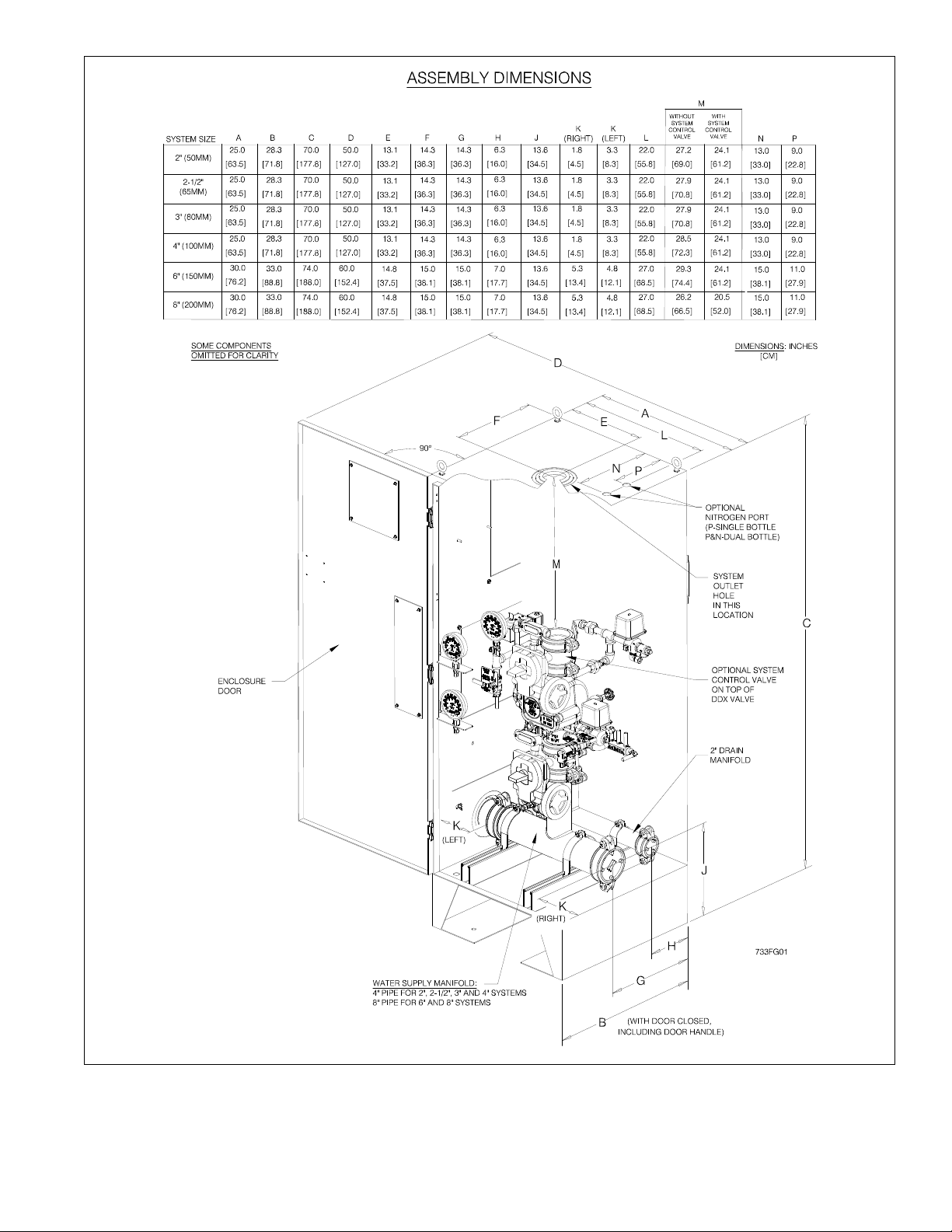
Fig. 1
3.
Page 4
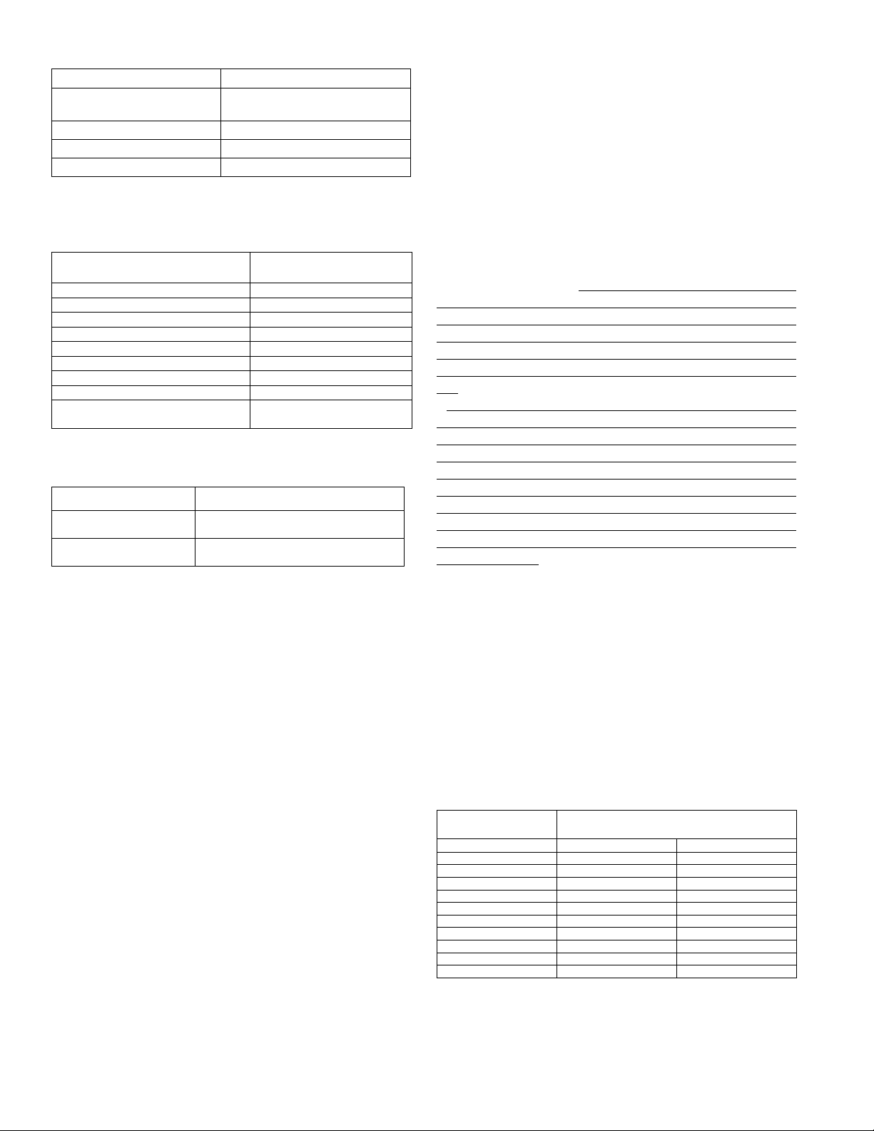
3. Shipping Weight:
System Size Weight
2” (50 mm), 2½” (65 mm)
& 3” (80 mm)
4” (100 mm) 710 lbs (322 kg)
6” (150 mm) 800 lbs (363 kg)
8" (200mm) 1350lbs (531kg)
554 lb. (252 kg)
4. Please reference Figure 1 for dimensions.
The following is a list of Technical Data Bulletins which de-
scribe the valves and devices which are used in the system:
Device
Model DDX Deluge Valve Reliable Bulletin 519
Type F Double Interlock Preaction Trim Reliable Bulletin 751
Low Air Pressure Switch Potter, 5401564
Alarm Pressure switch Potter, 5400928
Nitrogen Pressure Switch Potter, 5400930
Mechanical Sprinkler Alarm Reliable Bulletins 612/613
Releasing Control Panel Potter Manual #5403550
Fire Alarm Devices Reliable Bulletin 700
Desiccant Dryer
Reliable Bulletin #
(unless otherwise noted)
Wilkerson Catalog 9EM-
TK-190-4
The following table provides a quick reference to the vari-
ous programs (found in this bulletin and the Potter Manual
#5403550) that may be utilized with a Type F PrePaK:
Desired Application Program
Single Interlock,
Single Zone
Single Interlock,
Cross-Zoned
Note: The Model DDX Type F PrePak Double Interlock Preaction
system utilizes a solenoid controlled by single interlock programming in conjunction with a pneumatic (mechanical) actuator.
Potter Program #6
(Factory Setting)
Potter Program #7
Installation Requirements
The automatic sprinklers, releasing devices, fire
detection devices, manual pull stations, and signaling
devices which are utilized with the Reliable Model DDX
Type F PrePaK must be UL and/or ULC Listed or FM Approved, as applicable.
The steel enclosure and all the interconnecting piping
must be located indoors in a readily visible and accessible location and in an area that can be maintained at a
minimum temperature of 40°F (4°C). Note: Heat tracing
is not permitted. The solenoid valve is operated and
supervised by the Potter Model PFC-4410-RC Releasing Control Panel. Details on the electrical connections
of this system to the Potter Panel can be found in the
Potter Manual #5403550, Installation, Operation and
Instruction of PFC-4410-RC Releasing Control Panel
(this manual is included with other pertinent manuals
and shipped inside the enclosure). This panel is fully
zone and output programmable and may be adapted to
several applications. Hydrostatic Testing of DDX Valves
and DDX Systems.
Hydrostatic Testing of DDX Valves and
DDX Systems
As required by NFPA 13, fire sprinkler systems with working pressures up to and including 150 psi are to be hydrostatically tested at a water pressure of 200 psi. Fire sprinkler
systems with working pressures above 150 psi are required to
be hydrostatically tested at 50 psi above the system working
pressure. In addition to the hydrostatic tests described above,
dry pipe and double interlock preaction systems require an
additional low pressure air test.
In some cases, hydrostatic testing (in accordance with the
NFPA 13 requirements noted above) will result in pressures
that exceed the working pressure of the valve and trim kit for
the two-hour test period. The valve and applicable trim kit have
been tested, approved and listed under these conditions and
as such, hydrostatic testing in accordance with NFPA 13 is acceptable. In addition, the clapper can remain in the closed position and the trim kit need not be isolated, as each has been
designed to withstand hydrostatic testing as required by NFPA
13.
Hydrostatically testing the valve and trim to pressures higher
than their rating is limited to the hydrostatic test as referenced
by NFPA13. It does not address the occurrence(s) of a “water hammer” effect, which can indeed damage the valve. A
“water hammer” in the water supply piping of the valve can
create pressures in excess of the rated pressure and should
be avoided by all necessary means. This condition may be
created from improper fire pump settings, underground construction work, or an improper venting of trapped air in the water supply piping.
System Air / Nitrogen Pressure Requirements
The Model DDX Type F PrePaK includes gauges indicating
the pneumatic and water pressures of Model LP Dry Pilot Actuator. Table A specifies the air or nitrogen pressure level to be
applied to the Actuator. The factory installed Pressure Maintenance Device in the unit automatically provides adequate
makeup air or nitrogen flow to maintain supervisory pressure
with normal leakage for the system piping, while restricting the
flow of makeup air or nitrogen to allow for system operation.
Please note that when the optional Model B1 Accelerator is
to be utilized to expedite water-delivery time, the pneumatic
pressure must be not less than 15 psi (1.0 bar).
Table A
Water Pressure
psi (bar)
Maximum Not Less Than Not More Than
20 (1.4) 10 (0.7) 14 (0.9)
50 (3.4) 12 (0.8) 16 (1.1)
75 (5.2) 13 (0.9) 17 (1.2)
100 (6.9) 15 (1.0) 19 (1.3)
125 (8.6) 16 (1.1) 20 (1.4)
150 (10.3) 17 (1.2) 21 (1.4)
175 (12.1) 18 (1.2) 22 (1.5)
200 (13.8) 19 (1.3) 23 (1.6)
225 (15.5) 21 (1.5) 25 (1.7)
250 (17.2) 22 (1.5) 26 (1.8)
Supervisory Air or Nitrogen Pressure in
Sprinkler System, psi (bar)
4.
Page 5

Note: During system set-up, a higher pneumatic pressure may be required in order to properly set the Model
LP Dry Pilot Actuator. The dew point of the air supply
must be maintained below the lowest ambient temperature to which the preaction system will be exposed. Introduction of moisture into the system piping exposed
to freezing temperatures can create ice blockage which
could prevent proper system operation. As a minimum,
the supply of air should be taken from the area of lowest temperature within the protected area. The air supply
system must be carefully designed to prevent plugging
by frost deposits. Special requirements, such as those
in FME&R’s “Installation Guidelines for Refrigerated Storage” may need incorporated.
Nitrogen used in refrigerated area systems minimizes a
possibility of ice build-up and blockage inside the system
piping that could inhibit proper system operation. The dewpoint of nitrogen compressed to 20 psig (1.4 bar) pressure is
-46°F (-43.3°C), and -52°F (-46.7°C) when compressed to 10
psig (0.7 bar). High-pressure nitrogen cylinders can typically
be rented from a local source, with rental fees varying by
supplier and cylinder sizes. The calculated nitrogen supply
in lbs (kg) to pressurize various system capacities to 10 psi
(0.7 bar) at different freezer temperatures is shown in Table B.
A Nitrogen Kit is available as an option, for installations where
nitrogen is used as the supervisory gas. A “low-nitrogen” LED
is mounted onto the door of the Potter Model PFC-4410-RC
Releasing/Control Panel. It will illuminate when the nitrogen
pressure switch detects that the available nitrogen supply falls
to 100 psi (6,9 bar). The nitrogen source should be replaced
promptly upon operation of the pressure switch. If the nitrogen
supply is not replaced, the entire amount of make-up air will
come solely from the unit’s air compressor (if installed).
Table B
System
Capacity
Gal. (L)
250
(946)
500
(1891)
750
(2840)
1,000
(3785)
Note: To obtain required nitrogen supply (lbs.) for 15 psi (1.0
* When filled with the Rapid Air – Fill Shutoff Valve open.
20°F
(-6.7°C)
(1.65)
(2.50)
(3.30)
bar) or 22 psi (1.5 bar), multiply the tabulated values by
a factor of 1.5 or 2.2 respectively.
(1 bar = 100 kPa)
If the air compressor in the Model DDX Type F PrePaK is
used to initially fill the sprinkler system with air, the steel enclosure door should remain open to provide maximum intake air
flow to the air compressor. The air compressor is connected
to a storage tank. This tank functions as a reservoir, providing make-up air to compensate for small, intermittent leaks in
the sprinkler system. It should be noted that significant leaks
may overburden this storage tank, thereby causing the air
compressor to continuously cycle on and off.
Freezer Temperature
0°F
(-18°C)
1.90
(.86)
3.64
5.50
7.30
1.90
(.86)
3.80
(1.72)
5.70
(2.60)
7.60
(3.44)
-20°F
(-29°C)
2.00
(.90)
4.00
(1.81)
6.00
(2.72)
8.00
(3.62)
-40°F
(-40°C)
2.10
(.95)
4.20
(1.91)
6.30
(2.86)
8.33
(3.78)
-60°F
(-51°C)
2.20
(1.00)
4.40
(2.00)
6.60
(3.00)
8.80
(4.00)
Approx.
Fill Time
(min.)*
1
2
3
4
The factory-installed system air pressure switch may need
on-site adjustment to correspond with the air pressure values found in Table A. Adjustment, if required, should be
made according to Potter Bulletin 5401564 included with
the switch.
System Electrical Requirements
All releasing, alarm, and detection devices in the Reliable Model DDX Type F PrePaK are supervised by a Potter
Model PFC-4410-RC Releasing Control Panel. All of the terminals are translated to a water-tight terminal box mounted
on the interior of the enclosure. All field wiring is connected
to this terminal box. Note: The EOL (End of Line) resistors
have also been relocated.
The Reliable Model DDX PrePaK is delivered with six
factory-installed electrical devices. They consist of the following:
1. A system air pressure switch, which is used to monitor
sprinkler piping.
2. An alarm pressure switch, which indicates an actuation
of the deluge valve.
3. A normally-closed, releasing solenoid valve, which is
used to actuate the deluge valve.
4. A 1/2 HP (2”, 2-1/2”, & 3” valve), 1 HP (4” valve), or 1-1/2
HP (6” & 8” valve) air compressor with tank.
5. A supervised butterfly (main control) valve (Note: A sys-
tem side butterfly valve is available as an option).
6. A release control disable switch (RCDS) which is used
to disable the solenoid valve for test purposes.
The factory electrical connections of these devices,
along with information on the connection of detection devices (initiating zones 1 and 2), signaling devices, and supervisory outputs to the Potter PFC4410-RC Releasing Control
Panel are included in this bulletin. The power supply, standby emergency power supply, battery charger and rectifier
circuitry are all contained within the PFC4410 panel. Batteries that provide 90 hours of standby power are provided
with the panel. For additional information and detailed wiring
diagrams, please refer to Potter Manual #5403550 (Installation, Operation and Instruction of PFC4410-RC Releasing
Control Panel).
Note: In order for the solenoid valve to maintain a warranty it
must remain sealed as it came from the factory. If there are
concerns about the valve’s internal components, immediate replacement is recommended.
System Operation (Double Interlock)
To fully activate (discharge water from) the Reliable Model
DDX Type F PrePaK system, a fire detection device must activate and pneumatic pressure must be lost from the sprinkler system piping (normally from the activation of one or
more fire sprinklers).
When the system is properly set for service, the water supply pressure simultaneously acts on both the underside of
the deluge valve’s clapper and on the valve’s push rod by
means of the pressurized push rod chamber. The resultant
pressure force acting on the push rod, in unison with the mechanical advantage of the deluge valve lever, is more than
sufficient to hold the valve clapper in the closed position
against the water supply pressure.
5.
Page 6

Energizing the releasing solenoid valve is only one of the
events required towards opening the deluge valve. Air pressure in the sprinkler system must also be reduced to a level
low enough to activate the Model LP Dry Pilot Actuator. Both
of these events allows the deluge valve’s push-rod chamber
to be vented to drain through its outlet. Since the push-rod
chamber pressure cannot be replenished through the inlet
restriction as rapidly as it is vented, the pressure falls rapidly.
When the push-rod chamber pressure drops below onethird of the water supply pressure, the force acting beneath
the valve clapper becomes greater than the push-rod force
acting on the lever which causes the clapper to open. Refer
to Reliable Technical Bulletin 751 for further details.
Once the clapper has opened, the lever acts as a latch,
preventing the clapper from returning to the closed position.
Water from the supply flows through the deluge valve into
the system piping and also through the alarm outlet to activate water flow alarm devices. Note that the solenoid valve
will be maintained open by the Potter Model PFC-4410-RC
Releasing/Control Panel latching feature until it is reset for
operation.
After system shutdown and draining, the Model DDX Deluge Valve clapper is easily reset without special tools using the external reset feature. Restore detection devices by
resetting or replacing any operated device. Once detection
devices are restored the system can be reset (see Resetting
Model DDX Type F Double Interlock Preaction System).
Resetting Model DDX Type F Double Interlock
Preaction System
1. Close the valve controlling water supply to the Deluge Valve and close the air or nitrogen supply to the
sprinkler system.
2. Close the pushrod chamber supply valve.
3. Open main drain valve and drain system.
4. Open all drain valves and vents at low points throughout the system, closing them when flow of water has
stopped. Open the Model B Manual Emergency Station
to relieve pressure in the pushrod chamber of the Deluge
Valve.
5. With the alarm line valve open, push in the plunger of
ball drip valve, forcing the ball from its seat, and drain the
alarm line.
6. With the Model B Manual Emergency Station open,
push in and rotate the Deluge Valve’s external reset knob
counterclockwise (when facing the valve), until you hear
a distinct noise indicating that the clapper has reset.
Note: The reset knob can be rotated only while pressure
in the pushrod chamber is vented to atmospheric conditions (0 psig).
7. Inspect and replace any portion of the detection system and/or sprinkler system subjected to fire conditions.
8. Open the pushrod chamber supply valve and allow
water to fill the pushrod chamber. Close the Model B
Manual Emergency Station.
9. Purge all air from the actuation piping: Open the solenoid valve by operating a detector or an electric manual
emergency station. Note that the Model LP Dry Pilot Actuator should also be open since there is no pneumatic
pressure on the system.
10. While water is flowing through the solenoid valve
AND the actuator, cause the actuator to close first by applying air or nitrogen pressure to the system.
11. Open the air or nitrogen supply quick fill valve to restore supervisory pressure in the sprinkler system and
close the dry pilot actuator. Allow the pressure to build
to the level specified in Table A, then set the pneumatic
supply to automatic operation. (Note: To build supervisory air pressure in the sprinkler system, it may be necessary to temporarily close the main drain valve and the
alarm line valve until air pressure has built up to the recommended level.)
12. After the Model LP Dry Pilot Actuator has been set,
close the solenoid valve by resetting the release control
panel. (All detectors and manual pull stations must be in
a normal state before the panel can be reset.)
Note: It is important that the piping between the solenoid valve and the dry pilot actuator is filled with water
and not air. This is accomplished by closing the dry pilot
actuator FIRST while water is flowing through the device
and closing the solenoid valve only AFTER the actuator
is completely set.
13. Open the alarm line valve. Verify the main drain valve
is open. Slightly open the main valve controlling water
supply to the Model DDX Deluge Valve, closing the main
drain valve when water flows. Observe if water leaks
through the ball drip valve. If no leak occurs, the Deluge
Valve clapper is sealed. Slowly open the main valve controlling water supply until fully open and verify that it is
properly monitored.
14. Verify that the pushrod chamber supply valve and
alarm line valve are open. The pushrod chamber supply
valve must remain open when the Deluge Valve has been
reset, to maintain water pressure in the pushrod chamber.
15. Verify that the Model B Manual Emergency Station is
secured in the OFF position with the appropriate nylon
tie.
Inspection and Testing
1. Water supply — Confirm that valves controlling water
supply to the Deluge Valve are opened fully and properly
monitored.
2. Alarm line — Confirm that the alarm line valve is open
and remains in this position.
3. Other trim valves — Confirm that the pushrod chamber supply valve is open, as well as all pressure gauge
valves. The main drain valve, condensate drain valve,
and alarm test valve should be closed.
4. Ball drip valve — Push in on the plunger to be sure
ball check is off its seat. If no water appears, the Deluge
Valve water seat is tight. Inspect the bleed hole on the
underside of the pushrod chamber for leakage.
6.
Page 7

5. Dry pilot trim — Inspect air pressure for conformance
to Table A.
6. Releasing device — Check outlet of the releasing device (i.e., solenoid valve and hydraulic manual emergency station) for leakage. Also verify that tubing drain lines
from releasing devices are not pinched or crushed which
could prevent proper releasing of the Deluge Valve.
7. Testing alarms — Open the alarm test valve permitting water from the supply to flow to the electric sprinkler
alarm switch and to the mechanical sprinkler alarm (water motor). After testing, close this valve securely. Push
in on the plunger of ball drip valve until all water has
drained from the alarm line.
8. Operational test — Open the Model B Manual Emergency Station. Alternatively, operate the electrical detection system and deplete pneumatic pressure from the
sprinkler system.
Note: AN OPERATIONAL TEST WILL CAUSE THE DELUGE VALVE TO OPEN AND FLOW WATER INTO THE
SPRINKLER SYSTEM.
9. Secure the Model B Manual Emergency Station in the
OFF position with nylon tie after Deluge Valve is reset.
Testing Detection System Without Operating
Deluge Valve
1. Close the valve controlling water supply to the deluge valve and open the main drain valve.
2. Verify that valve supplying hydraulic pressure to the
piston/pushrod chamber is open, allowing water to enter
the pushrod chamber.
3. Operate the electrical detection system and deplete
pneumatic pressure from the sprinkler system.
4. Operation of the detection combined with loss of
pneumatic pressure must result in a sudden drop of water pressure in the pushrod chamber, as indicated by the
pressure gauge on the hydraulic release trim.
5. Reset the valve per the reset instructions.
Maintenance
The owner is responsible for maintaining the fire protection system in proper operating condition. Any system
maintenance or testing that involves placing a control
valve or detection/control system out of service may
eliminate the fire protection that is provided by the fire
protection system.
The Reliable Model DDX valve and associated equipment shall periodically be given a thorough inspection
and test. NFPA 25, “Inspection, Testing, and Maintenance of Water Based Fire Protection Systems,” provides
minimum maintenance requirements. System components shall be tested, operated, cleaned, and inspected
at least annually, and parts replaced as required. Replace any components found to be corroded, damaged,
worn, or non-operable. Increase the frequency of inspections when the valve is exposed to corrosive conditions
or chemicals that could impact materials or operation of
the assembly.
If face plate is removed during maintenance, torque face
plate bolts to the following values during re-installation:
35 ft-lbs. (47 N-m) for 2” through 4” valves
70 ft-lbs. (95 N-m) for 6”-8” valves
Draining Excess/Condensate Water from the
System
1. Notify the owner and monitoring company that maintenance is being performed on the system.
2. Close the main water control valve.
3. Open the Main Drain Valve.
4. Open the Condensate Drain Valve until all water has
drained.
5. Close Condensate Drain Valve.
6. Partially open the Main Water Control Valve.
7. Slowly close the Main Drain Valve.
8. Fully open the Main Water Control Valve.
9. Notify the owner and monitoring company that the
system has been returned to service.
SOLENOID VALVE INSPECTIONS, TESTS
AND MAINTENANCE
WARNING: THE OWNER IS RESPONSIBLE FOR MAINTAINING THE FIRE PROTECTION SYSTEM IN PROPER OPERATING CONDITION. ANY SYSTEM MAINTENANCE OR TESTING THAT INVOLVES PLACING A
CONTROL VALVE OR DETECTION SYSTEM OUT OF
SERVICE MAY ELIMINATE THE FIRE PROTECTION
OF THAT SYSTEM. PRIOR TO PROCEEDING, NOTIFY
ALL AUTHORITIES HAVING JURISDICTION. CONSIDERATION SHOULD BE GIVEN TO EMPLOYMENT OF
A FIRE PATROL IN THE AFFECTED AREA.
WARNING: PRIOR TO OPERATING THE SOLENOID
VALVE, BE SURE TO CLOSE THE SYSTEM CONTROL
VALVE TO AVOID UNINTENTIONAL OPERATION OF
THE DELUGE VALVE
1. Inspections: It is imperative that the system be inspected and tested in accordance with NFPA 25 on a
regular basis. The frequency of the inspections may
vary due to contaminated water supplies, corrosive
water supplies, or corrosive atmospheres. In addition, the alarm devices, detection systems, or other
connected trim may require a more frequent schedule. Refer to the system description and applicable
codes for minimum requirements.
2. The valve must be inspected at least monthly for
cracks, corrosion, leakage, etc., cleaned and replaced as necessary.
3. If leakage is suspected through the solenoid valve, it
should be replaced.
7.
Page 8

8.
Note: Trim valve location is common to wet pilot
line, dry pilot line, and electric release systems.
Fig. 2
Page 9

Fig. 3
9.
Page 10

Fig. 4
10.
Page 11

Fig. 5
11.
Page 12

12.
Fig. 6
Page 13

13.
Fig. 7
Page 14

14.
Fig. 8 — Wiring Diagram
Page 15

Fig. 9 — Wiring Diagram
15.
Page 16

Single Interlock, Single Detection Zone
Potter Program #6
1. Apply power to panel.
2. Slide the program switch down.
3. Press the FUNCTION button until the display reads
“PASSWORD=000.”
4. To enter a password, press the SELECT button until
the proper number is displayed above the “^” symbol; then press the SET button to move to the next
digit. After entering the third number the display will
change. (All panels are shipped with a “000” password.)
5. Press the FUNCTION button until the display reads
“PROGRAM ##.” (the second “#” character refers to
the current program number between “0” and “24”).
6. Press the SELECT button until the display reads
“PROGRAM #6.”
7. Press the SET button
8. The panel is completely programmed except for the
custom banner and zone messages. Slide the program switch back up.
POTTER PROGRAM #6
ZONES
OUTPUTS
#1 ALARM X
#2 WATERFLOW X
#3 SUPERVISORY X X
#4 RELEASE X
Supervisory 2
(1)
#1
Conventional
(2)
#2
Conventional
(2)
#3
Waterflow
Low Air Supervisory
#4
INPUTS: 1 conventional zone, 1 manual release zone, 1 waterflow zone, 1 low air zone, 1 supervisory zone.
OUTPUTS: 1 general alarm bell, 1 waterflow bell, 1 supervisory bell, 1 solenoid release circuit.
OPERATION: Activation of either conventional zone (or operation of the manual pull station within the PrePak cabi-
net) will operate the solenoid release circuit and the general alarm bell. Activation of the waterflow
zone will operate the waterflow bell. Activation of either the low air zone or the supervisory zone will
operate the supervisory bell. When either Zone #1 or #2 is in alarm, Output #1 (general alarm) and
Output #4 (solenoid release) will operate. When Zone #3 is in alarm, Output #2 (waterflow bell) will
operate. When either Zone #4 or the supervisory zone is activated, Output #3 (supervisory bell) will
operate.
Note:
(1)
The Butterfly valve in the PrePaK assembly is connected to Supervisory 2 input of the Potter PFC-4410RC Releas-
ing/Control panel
(2)
The emergency manual release within the PrePak cabinet is wired into the conventional detection zones 1 and 2, and is de-
signed to release the solenoid for setup and testing purposes.
For additional Information, please refer to the “Installation, Operation, and Instruction Manual” for the Potter
PFC4410-RC Releasing Control Panel (provided with the unit).
16.
Page 17

Single Interlock, Cross Zoned Detection
Potter Program #7
1. Apply power to panel.
2. Slide the program switch down.
3. Press the FUNCTION button until the display reads
“PASSWORD = 000.”
4. To enter a password, press the SELECT button until
the proper number is displayed above the “^” symbol; then press the SET button to move to the next
digit. After entering the third number the display will
change. (All panels are shipped with a “000” pass-
word).
5. Press the FUNCTION button until the display reads
“PROGRAM ##.” (the second “#” character refers to
the current program number between “0” and “24”).
6. Press the SELECT button until the display reads
“PROGRAM #7.”
7. Press the SET button.
8. The panel is completely programmed except for the
custom banner and zone messages. Slide the program switch back up.
POTTER PROGRAM #7
ZONES
OUTPUTS
#1 ALARM X X
#2 WATERFLOW X
#3 SUPERVISORY X X
#4 RELEASE XX XX
Supervisory 2
(1)
#1
Conventional
(2)
INPUTS: 2 conventional zones (cross-zoned), 1 waterflow zone, 1 low air zone, 1 supervisory zone.
OUTPUTS: 1 general alarm bell, 1 waterflow bell, 1 supervisory bell, 1 solenoid release circuit.
OPERATION: Activation of both conventional zones at the same time (or operation of the manual pull station within
the PrePak cabinet) will operate the solenoid release circuit and the general alarm bell. Activation of
either conventional zone will operate the general alarm bell. Activation of the waterflow zone will operate the waterflow bell. Activation of either the low air zone or the supervisory zone will operate the
supervisory bell. When either Zone #1 or #2 is in alarm, Output #1 (general alarm) will operate. When
Zones #1 and #2 are in alarm at the same time, Output #4 (solenoid release) and Output #1(general
alarm) will operate. When Zone #3 is in alarm, Output #2 (waterflow bell) will operate. When either
Zone #4 or the supervisory zone is activated, Output #3 (supervisory bell) will operate.
#2
Conventional
(2)
#3
Waterflow
Low Air Supervisory
#4
Note:
(1)
The Butterfly valve in the PrePaK assembly is connected to Supervisory 2 input of the Potter PFC-4410RC Releas-
ing/Control panel
(2)
The emergency manual release within the PrePak cabinet is wired into the conventional detection zones 1 and 2, and is de-
signed to release the solenoid for setup and testing purposes.
For additional Information, please refer to the “Installation, Operation, and Instruction Manual” for the Potter
PFC4410-RC Releasing Control Panel (provided with the unit).
17.
Page 18

Manufactured by
The equipment presented in this bulletin is to be installed in accordance with the latest published Standards of the National Fire Protection Association, Factory
Mutual Research Corporation, or other similar organizations and also with the provisions of governmental codes or ordinances whenever applicable.
Products manufactured and distributed by Reliable have been protecting life and property for almost 100 years.
Ordering Information: PrePak Part Number Configuration
655 U V W X Y Z 0
Reliable Automatic Sprinkler Co., Inc.
(800) 431-1588 Sales Offices
(800) 848-6051 Sales Fax
(914) 829-2042 Corporate Offices
www.reliablesprinkler.com Internet Address
EG. Printed in U.S.A. 02/19
Revision lines indicate updated or new data.
P/N 9999970383
Recycled
Paper
DDX Valve Size/System
Side Control Valve
U
2 = 2”
0 = 2-1/2”
3 = 3” 3 = Dry Pipe
4 = 4” 4 = Deluge Wet Pilot
Trim Type
V
1 = Preaction Type D
Sin gle/Double Interlock
2 = Preaction Type F
Double Interlock
(4)
(1)
(1)(2)
Solenoid
Valve
W
0 = None 0 = None 0 = None 0 = None
(4)
1 = 175 psi
Rated
2 = 300 psi
Rated
Releasing/Control
Panel
X
1 = Potter PFC4410RC
Air Compressor
(3)
Y
1 = 1/2 HP 115 VAC
(systems up to 3” in size)
2 = 1 HP 115 VAC
(for 4” systems)
3 = 1-1/2 HP 115 VAC
(for 6” & 8” systems)
Supply w/ Auto Switchover
System Air Devices
Z
1 = Nitrogen Supply Kit
2 = Nitrogen Supply Kit &
Model B Accelerator
3 = NS-ASAM (Nitrogen
and Monitoring)
4 = NS-ASAM (Nitrogen
6 = 6” 5 = Deluge Dry Pilot
(1)
Supply w/ Auto Switchover
and Monitoring) & Model
B Accelerator
8 = 8”
A = 2” w/ System Side
Control Valve
B = 2-1/2” w/ System Side
Control Valve
C = 3” w/ System Side
Control Valve
6 = Deluge Electric
Actuation
7 = Preaction Single
Interlock Dry Pilot
8 = Preaction Single
Interlock Wet Pilot
9 = Preaction Type PL
Double Interlock
(2)
(1)
(1)
(1) (4)
5= Model B Accelerator
6 = Desiccant Kit
7 = Desiccant Kit &
Model B Accelerator
D = 4” w/ System Side
Control Valve
E = 6” w/ System Side
Control Valve
F =8” w/ System Side
Control Valve
Note:
(1)
No Solenoid Valve or Control Panel are utilized with this trim. If selected, the 6th and 7th digits in the P/N are required to be “0” (None).
(2)
No Air Compressor or System Air Devices are utilized with this trim. If selected, the 8th and 9th digits in the P/N are required to be “0” (None).
(3)
Air Compressor sizing may differ if specified sprinkler system has an uncommon volume capacity.
(4)
Type D is Electric/Electric Actuation; Type F is Electric/Pneumatic Actuation; Type PL is Pneumatic/Pneumatic Actuation.
 Loading...