

Page 1
FPI FIREPLACE PRODUCTS INTERNATIONAL LTD.
6988 Venture St., Delta, BC Canada, V4G 1H4
918-515
G36D Zero Clearance Direct Vent Gas Fireplace
WARNING: If the information in these instructions are not followed exactly,
vapors and liquids in the vicinity of this or any other appliance. Installation
What to do if you smell gas:
Do not touch any electrical switch:
Do not touch any electrical switch:
Do not touch any electrical switch:
Do not touch any electrical switch:
do not use any phone in your building
Immediately call your gas supplier
Immediately call your gas supplier
Immediately call your gas supplier
Immediately call your gas supplier
from a neighbour's phone. Follow the
gas supplier's instructions.
If you cannot reach your gas supplier,
If you cannot reach your gas supplier,
If you cannot reach your gas supplier,
If you cannot reach your gas supplier,
call the fi re department.
www.regency-fi re.com
Installer: Please complete the details on the back cover
and leave this manual with the homeowner.
Homeowner: Please keep these instructions for future reference.
Page 2
®
G36D Zero Clearance Direct Vent Gas Fireplace
You are the owner of a state-of-the-art Gas Fireplace by
FIREPLACE PRODUCTS
®
®
product has been tested and listed by Warnock Hersey as a Direct Vent Wall Furnace to the following standards: VENTED GAS
®
®
Mobile/Manufactured Home Listed appliance
®
Mobile/Manufactured Home listed appliance
Page 3

®
G36D Zero Clearance Direct Vent Gas Fireplace
....................................................................
...................................................
Aeration
Adjustment
............
...........................................
...............................................................
.............................................................
.......................................
WARRANT
Y
............................................................
..................................................
Additional
...............................................
...................................................
Venting
.......................................................
Venting
...........................
...............................................
Vertical Termination
Venting Arrangements - Vertical Terminations
................
.............................................................
..........................................
1:
............................................
3:
...........................................................
Page 4
®
G36D Zero Clearance Direct Vent Gas Fireplace
UltraGlow
®
units are constantly being
APPAREIL FONCTIONNANT AU GAZ PROPANE
CONCU POUR ETRE POELE:
Pression d'allimentation
minimum
Pression à la tubulure d' chappement lev
e
Pression à la tubulure d' chappement basse
Grandeur de l'injecteur
D bit minimum selon
D bit maximum selon
l'altitude
Modéle
G36D-LP1
é é
é
é
é
é
Calorifique
Calorifique
DO NOT REMOVE THIS LABEL / NE PAS ENLEVER CETTE ÉTIQUETTE
300
NATURAL GAS:
Minimum supply pressure
Manifold pressure high
Manifold pressure
low
Orifice s
ize
Minimum input
Maximum input
Altitude
Model G36D-NG1
L
PROPANE:
Minimum supply pressure
Manifold pressure high
Manifold pressure
low
Orifice s
ize
Minimum input
Maximum input
Altitude
Model G36D-LP1
L
DOO R SEAL: Please
che ck that the do or is
pro perly seale d
FPI Fireplace Products International Ltd.
Delta,
BC, Canada
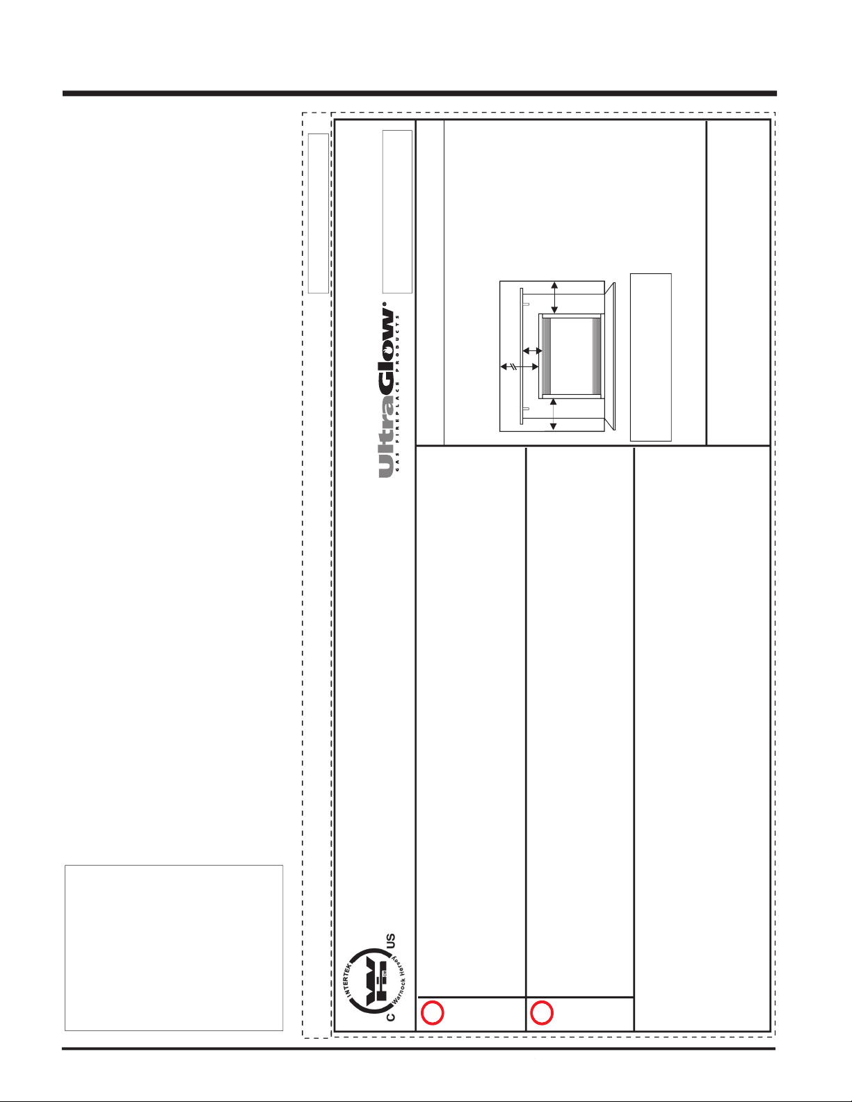
Minimum Clearances to Combustibles /
Degagement Minimum De Materiaux Combustibles
0" Clearance to
combustibles from
:
Mantel Clearances from
Top:
Side
Wall Clearance
from Side Facing
Alcove Clearances:
Minimum
Vent Clearances:
Top, sides, bottom and rear of unit
(A) Min. 7" (177mm
)
B) 6"
with Flush
Alcove approved for
Flush Louvers.
Max. Depth 36" (914mm)
Min. Widt
h 48" (1219mm),
Min. Height 72" (1229mm)
Horizontal To
p 2-1/2" (64mm)
Horizontal Side
Horizontal Bottom 1-1/2" (38mm
)
1-1/2" (38mm
)
Serial No./ No de serie
918-493
5" WC(1.25 kPa)
3.8" WC(0.95 kPa)
1.1" WC(0.27 kPa)
# 4
2 DMS
13,100 Btu/h (4.54 kW)
0-4500 ft/pi(0-1372 m)
26,000 B (8.79 )tu/h kW
12" WC(3.00 kPa)
11" W
C(2.74 kPa)
2.9" WC(0.72 kPa)
# 5
3 DMS
13,800 Btu/h (3.96 kW)
0-4500 ft/pi(0-1372 m)
26,000 B (7.91 )tu/h kW
APPAREIL FONCTIONNANT AU NATURAL GAZ
CONCU POUR ETRE POELE:
Pression d'allimentation
minimum
Pression à la tubulure d'
chappement lev e
Pression à la tubulure d'
chappement basse
Grandeur de l'injecteur
D bit minimum selon
D bit maximum selon
l'altitude
Modéle
G36D-NG1
é é é
é
é
é
Calorifique
Calorifique
VENTING: This appliance must be installed in accordance with the manufacturer's installation instructions and with local
codes, if any; if not, follow the current ANSI Z223.1 in the USA or the current CAN 1-B149 in Canada. For Manufactured
Home
Installation: This Direct Vent System Appliance must be installed in accordance with the manufacturer's
installation instructions
and Manufactured Home Construction and Safety Standard Title 24 CFR, Part 3280, or the
current Standard for Fire Safety Criteria for Manufactured Home Installations, Sites, and Communities ANSI/NFPA501A,
and with CAN/CSA Z240 MH Mobile Home Standard in Canada. This appliance is only for use with the type of gas
indicated
on the rating plate and may be installed in an aftermarket, permanently located, manufactured (mobile) home
where
not prohibited by local codes. See owner’s manual for details. This appliance is not convertible for use with other
gases, unless a certified kit is used.
Not for use
with solid fuel.
This vented gas fireplace is not for use with filters.
MAY BE INSTALLED IN MANUFACTURED (MOBILE)
HOMES AFTER FIRST SAL
E.
Listed:
Certified for/Certifi e pour:
Tested to:
Report No.
VENTED GAS FIREPLACE HEATER
CANADA and U.S.A.
Gas-Fired Appliances For Use At High Altitudes
476-3031-977
é
CAN/CGA-2.17-M91,
Vented Gas Fireplace Heaters ANSI Z21.88b-2003/CSA 2.33b-2003
Made in Canada/Fabrique au Canada
Duplicate S/N
B
B
32"
Ceilin
g
Wall
Wall
A
(See Instruction Manual for
Detailed Instructions)
Model/M
odele:
G36D-NG1
Model/Modele:
G36D-LP1
300
Page 5
®
G36D Zero Clearance Direct Vent Gas Fireplace
Check all clearances to combustibles. Refer
a) Locating Your Gas Stove
b) Clearances
c) Mantel Leg Clearances
d) Combustible Mantels
e) Framing and Finishing
f) Hearth Requirement
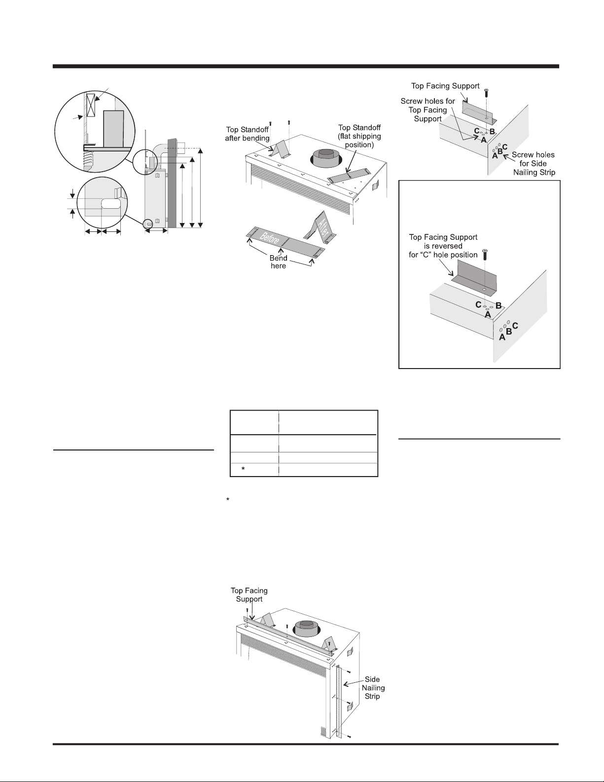
Assemble Top Standoffs and Top Facing
Install standard and optional features.
a. Log Set Installation
b. Standard Flush Door
c. Option 1: Remote Control
d. Option 2: Wall Switch
e. Option 3: Wall Thermostat
f. Installating the Optional Fan
Final check.
with these instructions. Carefully read all the
The appliance installation must conform
with local codes or, in the absence of local
The appliance when installed, must be
with the current National Electrical Code,
ANSI/NFPA 70 or CSA C22.1 Canadian
See general construction and assembly
This appliance must be connected to the
Inspect the venting system annually for
Venting terminals shall not be recessed into
Any safety glass removed for servicing
To prevent injury, do not allow anyone who
Wear gloves and safety glasses for protection
while doing required maintenance.
Be aware of electrical wiring locations in
walls and ceilings when cutting holes for
Un der no ci rc um stances sh ou ld t his
Installation and any repairs to this appliance
A professional service person should be
Do not slam shut or strike the glass door.
Under no circumstances should any solid
fuels (wood, paper, cardboard, coal, etc.)
The appliance area must be kept clear and
free of combustible materials, (gases and
AND AT LEAST ANNUALLY BY A
APPLIANCE SHOULD BE LOCATED
WARNING: FAILURE TO INSTALL THIS
APPLIANCE CORRECTLY WILL VOID
YOUR WARRANTY AND MAY CAUSE
A SERIOUS HOUSE FIRE.
AND SHOULD STAY AWAY TO AVOID
YOUN G CHILD REN SHOULD B E
ANCE.
Page 6
®
G36D Zero Clearance Direct Vent Gas Fireplace
Clocking the appliance to ensure the correct
If required, adjusting the primary air to ensure
When selecting a location for your fi replace,
Provi d e a d e q u a t e clear a n c e s f o r
The appliance must be installed on a fl at,
width and depth of the appliance.
The G36D Direct Vent Gas Fireplace can be
This appliance is Liste d for bedroom
The G36D Direct Vent Gas Fireplace is
A)
Flat on Wall
Flat on Wall Corner
Recessed into
Wall/Alcove
Corner
ADDITIONAL
Ensure that structural members are not cut
Ensure proper grounding using the #8
Page 7
®
G36D Zero Clearance Direct Vent Gas Fireplace
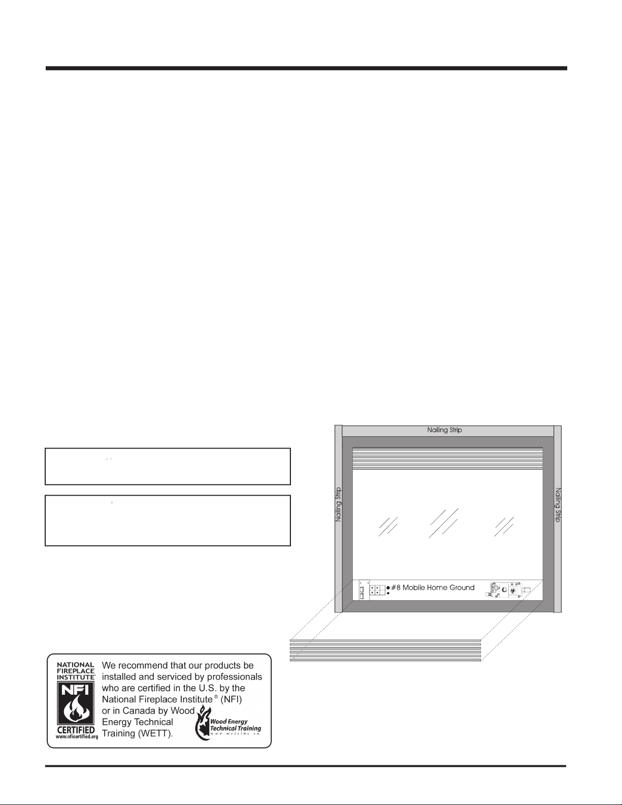
Determine the total thickness of facing
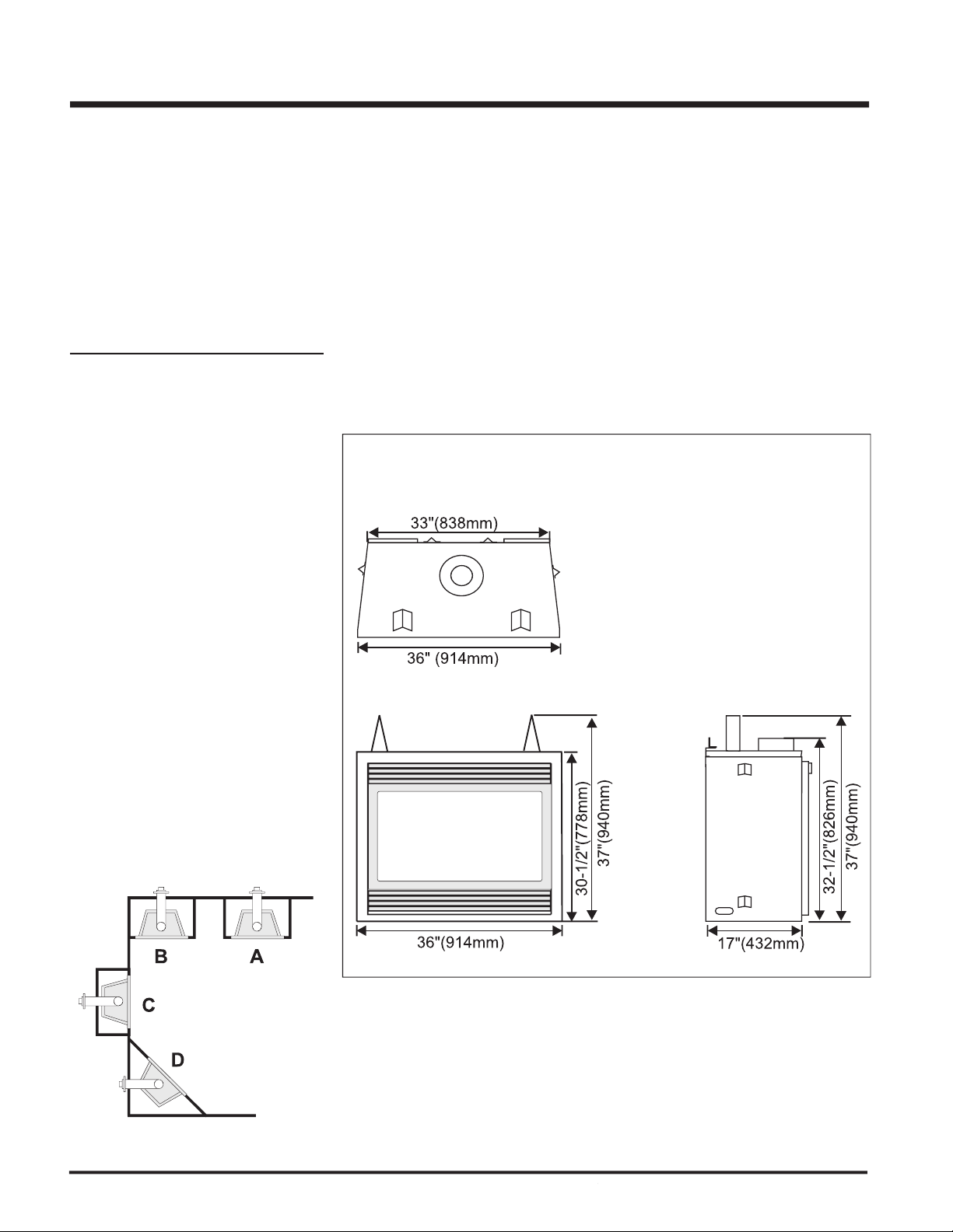
Frame in the enclosure for the unit with
framing material. The framed opening is
37-1/4" high x 36-1/4" wide x 17-3/8" deep
A major cause of chimney related fi res is
vent system be installed only in accordance
with these instructions.
Back
0" (0mm)
Side
0" (0mm)
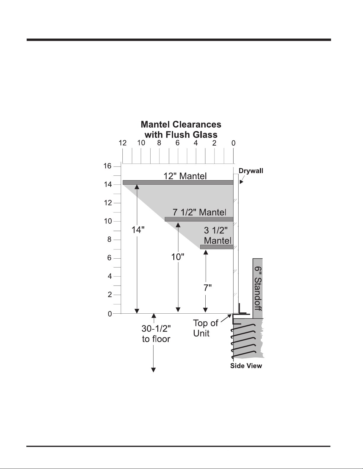
Floor
0" (0mm)
Mantel*
Ceiling
from top of unit. 32" (1016mm)
Flush Front
6" (152mm)
Top 2-1/2" (64mm)
Side 1-1/2" (38mm)
Bottom 1-1/2" (38mm)
Vertical Vent Clearances
1-1/4" (32mm)
Alcove Clearances**:
Max. Depth
36" (914mm)
Min. Width
48" 1219mm)
Min. Height
72" 1829mm)
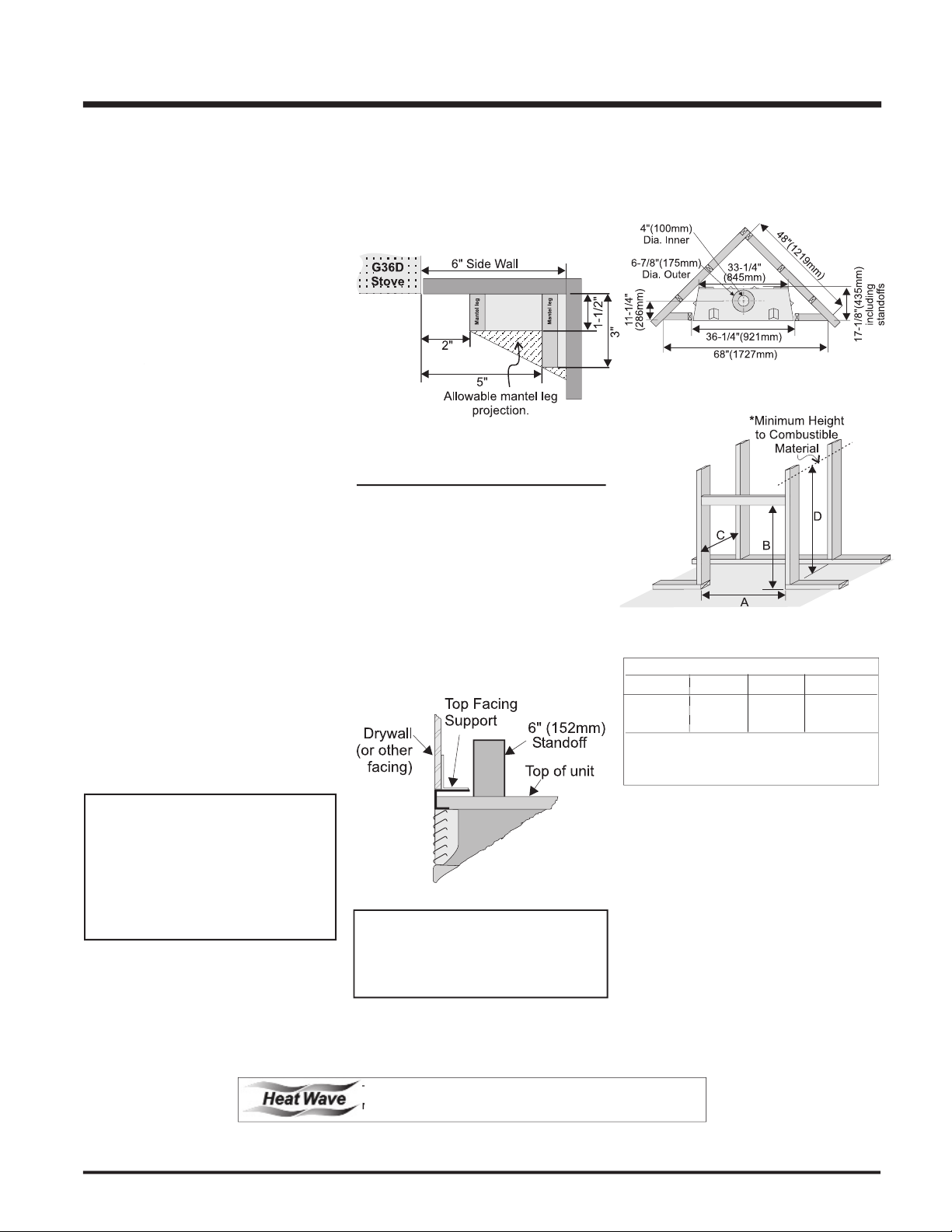
For exterior walls, insulate the enclosure to
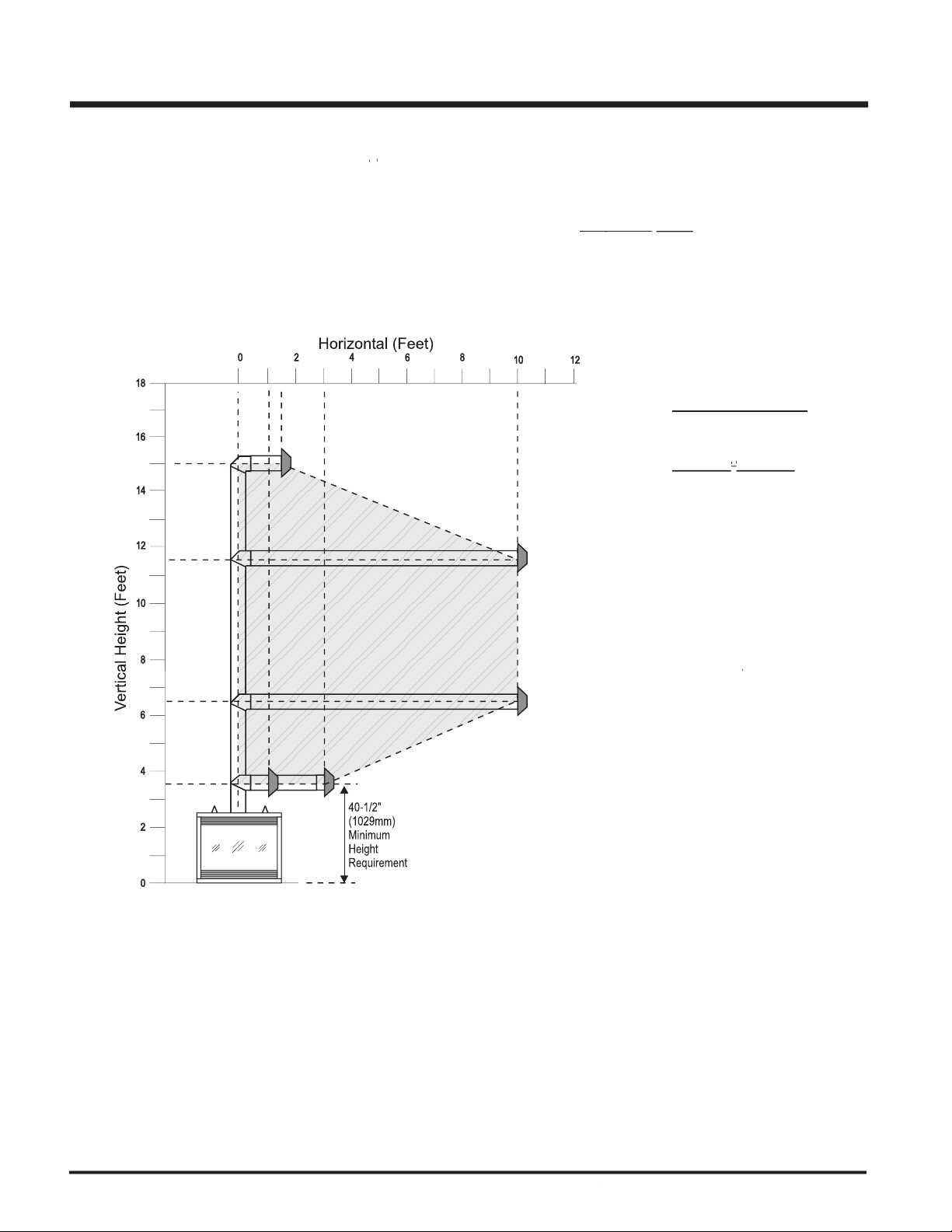
The top of the unit must not be closer than
WARNING:
Aseembly Prior to Installation" section for
Duct Kit has different clearance and framing
manual for details.
A B C D
36-1/4" 37-1/4" 17-3/8" 46-1/2"*
921mm 946mm 441mm 1181mm*
Page 8
®
G36D Zero Clearance Direct Vent Gas Fireplace
with a non-combustible board.
Page 9
®
G36D Zero Clearance Direct Vent Gas Fireplace
For "C" screw position the top facing support
Mount Top Facing Support using the 3
facing depth.
Use the same screw hole position for the
VENTING
17-1/8"
3-1/2"
4"
2"
40-1/2"
37
”
32-1/2"
10" dia. hole
through wall
for Flex
or for DuraVent
1/2"
Drywall
To
p Header
Opening for gas
connection
Use steel studs for framing where the
1-1/2" (38mm) clearance from the vent to
with 2 screws per standoff (on opposite
A 1/2" / 13mm
1-1/4" / 32mm
Page 10
®
G36D Zero Clearance Direct Vent Gas Fireplace
.
B
B
B
B
A
C
V
V
V
V
V
V
V
A
A
V
Fixed
Fixed
Openable
Closed
Closed
Openabl
e
N
L
B
E
B
M
D
F
K
H
j
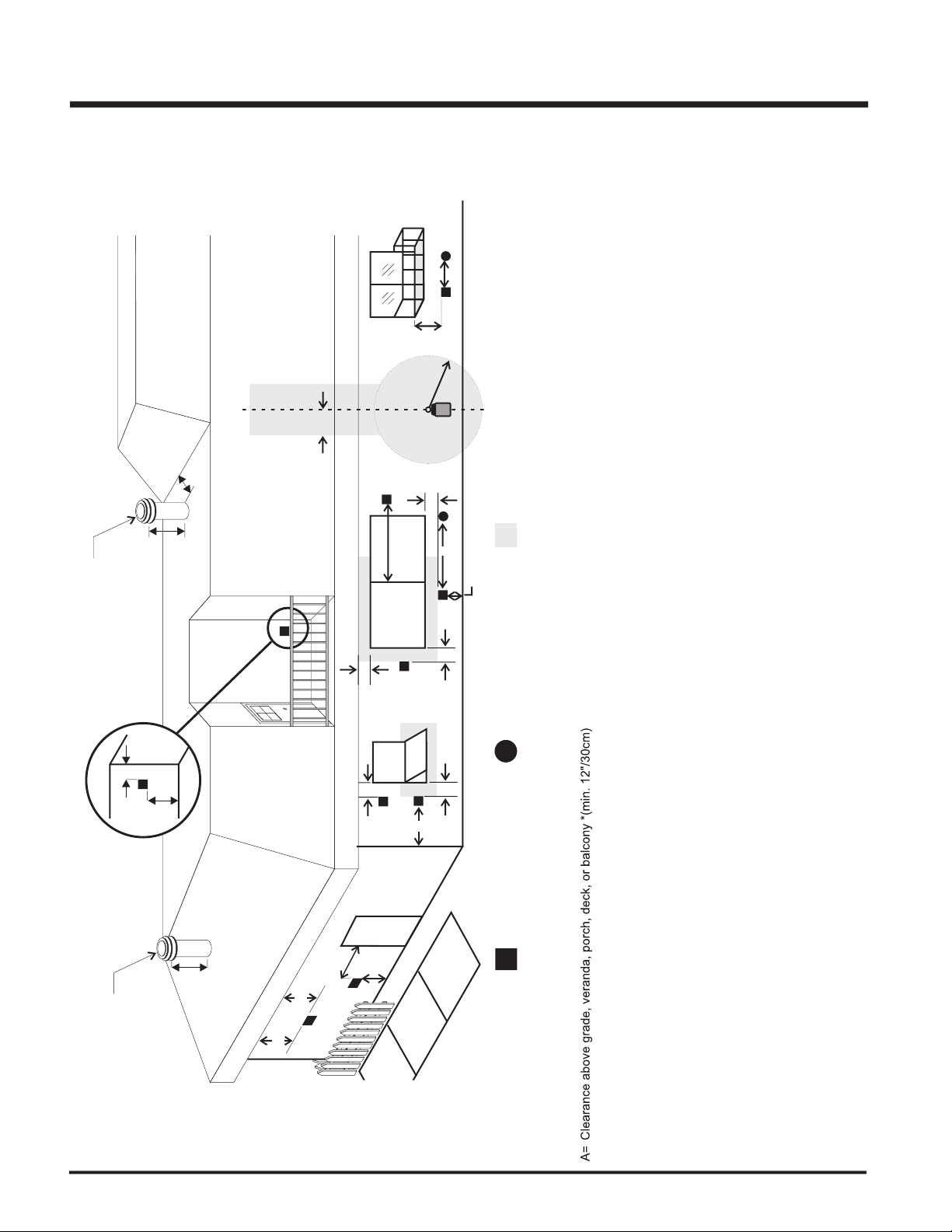
Vertical
Termination
V
Vent
terminal
Area
where
terminal
is
not
permited
A
Air
supply
outlet
24"
V
A
G
Inside
corner
det
ail
V
24"
18"
Vertical
Termination
A= Clearance above grade, veranda, porch, deck, or balcony *(min. 12"/30cm)
AstroCap
AstroCap
Page 11
®
G36D Zero Clearance Direct Vent Gas Fireplace
VENTING
®
®
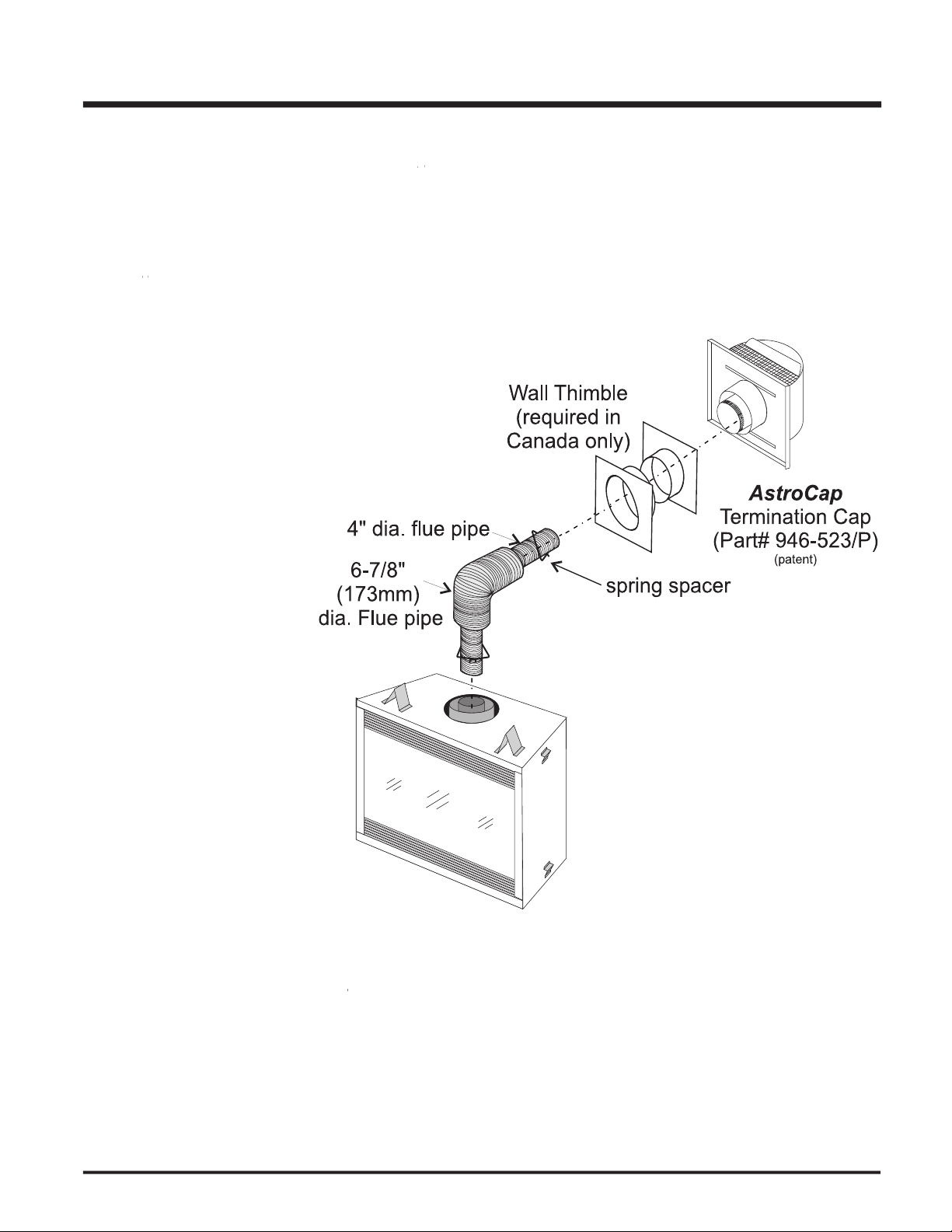
Direct Vent System (Flex)
®
®
Direct Vent Flex Termination Kit (Part # 946-515) includes all the parts
®
may be used for Flex installations.
6-7/8" dia. fl exible liner (4 ft. length)
4" dia. fl exible liner (4 ft. length)
spring spacers (4)
thimble (2)
AstroCap
termination cap (1)
screws (12)
tube of Mill Pac (1)
plated screws (8)
screws #8 x 1-1/2" Drill Point, Stainless Steel (4)
Page 12
®
G36D Zero Clearance Direct Vent Gas Fireplace
All Simpson Dura-Vent components are available directly from FPI.
®
Direct VentGS
®
Direct Vent
®
Adjustable Length, 11"-14", Galv. 911 4DT-AJ N/A
Adjustable Length, 11"-14", Black 911B 4DT-AJB N/A
Adjustable Length, 17"-24", Black 917B N/A N/A
Adjustable Length, 7" Galvinized N/A N/A 4D7A
Adjustable Length, 7" Black N/A N/A 4D7AB
Adjustable Length, 12" Galvinized N/A N/A 4D12A
Adjustable Length, 12" Black N/A N/A 4D12AB
Elbow, Galvinized 945 4DT-EL45 4D45L
Elbow, Black 945B 4DT-EL45B 4D45LB
Elbow, Swivel, Galvinized 945G N/A N/A
Elbow, Swivel, Black 945BG N/A N/A
Elbow, Galvinized 990 4DT-EL90S 4D90LS
Elbow, Black 990B 4DT-EL90SB 4D90LBS
Elbow, Swivel, Galvinized 990G N/A N/A
Elbow, Swivel, Black 990BG N/A N/A
Attic Insulation Shield 12" N/A N/A 4DAIS12
Attic Insulation Shield - Cold Climates 36" N/A N/A 4DAIS36
Vertical Termination Kit 978 4DT-VKC 4DVTK
Verical Termination Cap 980 4DT-HVC 4DVC
Adjustable Flashing, 0/12-6/12 943 4DT-AF6 4DF
Adjustable Flashing, 6/12-12/12 943S 4DT-AF12 4DF12
Vinyl Siding Standoff 950 4DT-VS N/A
Vinyl Siding Shield Plate N/A 4DT-VSP N/A
#N/A
#N/A
#N/A
#N/A
#N/A
#N/A
#N/A
#N/A
#N/A
#N/A
#N/A
#N/A
#N/A
#N/A
#N/A
Page 13
®
G36D Zero Clearance Direct Vent Gas Fireplace
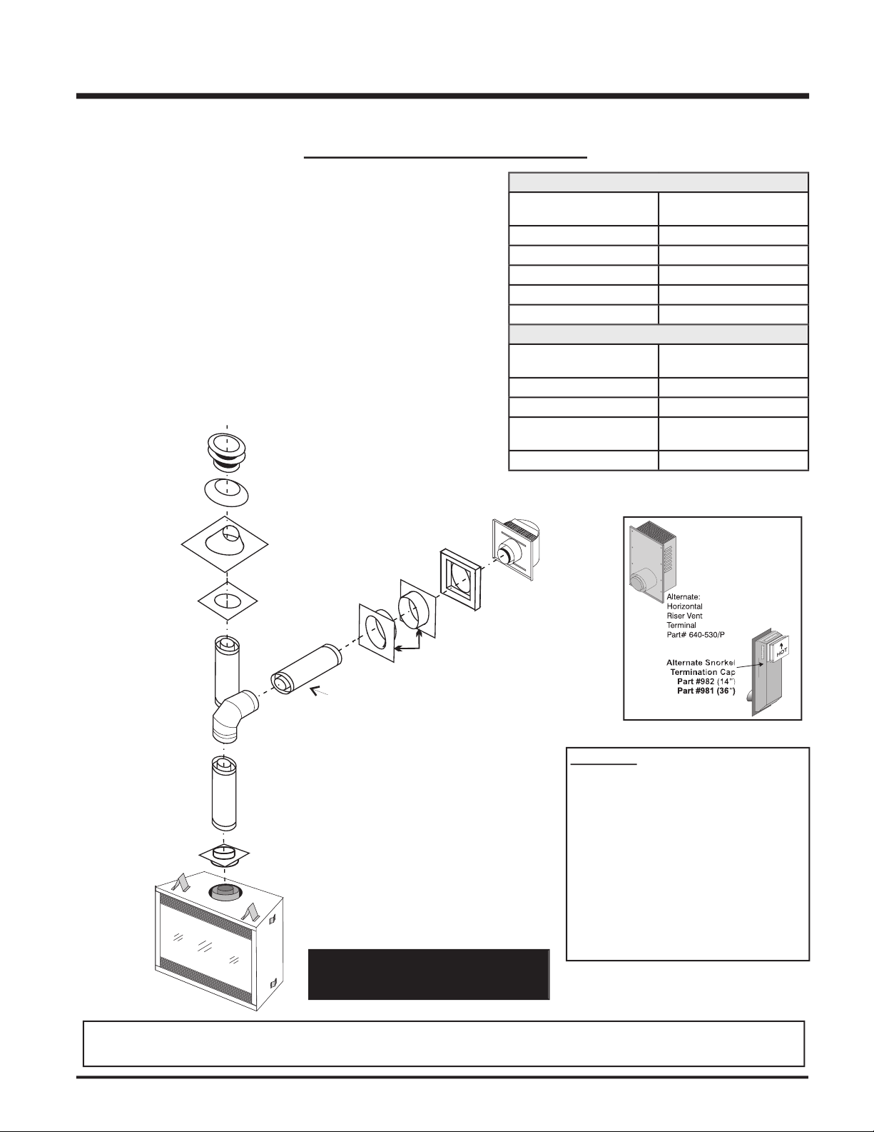
Rigid Pipe Adaptor
(Part# 510-994)
Pipe Length
Vertical
Terminal
Storm Collar
(Part # 953)
Flashing
943 or 943S
Ceiling Firestop
(Part # 963)
24" Pipe
Length
Adj.Pipe
Length
11" - 14-5/8"
90 Elbow
o
Horizontal
Termination Cap
(Part# 946-523/P)
Wall Thimble
(Part # 942)
Vinyl Siding
St
andoff (Optional)
(Part
#950)
1 Horizontal Termination Cap
1 90
Elbow
1 Rigid Pipe Adaptor
1 Wall Thimble
1 Length of pipe to suit wall thickness (see chart)
Alternate
American Metal Products Ameri Vent Direct Vent and Selkirk Direct-Temp.
AstroCap
is the proprietary trademark of FPI Fireplace Products International
for using a Rigid Pipe Adaptor in conjunction
with Dura-Vent Direct Vent GS, Selkirk Direct-
WARNING:
and FPI
Wall Thickness
Vent Length
12"
Wall Thickness
Vent Length
When using Rigid Vent piping other than
Simpson Dura-Vent, 3 screws must be
used to secure rigid pipe to adaptor.
Page 14
®
G36D Zero Clearance Direct Vent Gas Fireplace
DIRECT VENT SYSTEM (FLEX)
elbow
(two 45
All Rigid Pipe Systems
All Rigid Pipe Systems
Flex Vent
A v ent g uar d s hou ld be u se d
whenever the termination is lower
®
Direct Vent System
Page 15

®
G36D Zero Clearance Direct Vent Gas Fireplace
DIRECT VENT SYSTEM (FLEX)
elbows (two 45
elbow).
elbows are permitted.
2) A minimum of 6 ft. (1.8m) vertical from base of unit is required if two 90
elbows are used.
3) Minimum distance between elbows is 2 ft. (0.6m).
4) Determine the permitted range of horizontal termination arrangements by using chart in the "Rigid Pepi Venting
Arrangements - Vertical Termination" section and deducting 3 ft. (0.9m) from the maximum horizontal distance for the
second 90
All Rigid Pipe Systems
All Rigid Pipe Systems
Flex Vent
and Finishing," & "Hearth Requirement" sections.
A vent guard should be used whenever the
Page 16

®
G36D Zero Clearance Direct Vent Gas Fireplace
elbows (two 45
elbow) with
vent systems for Propane and
elbow (two 45
elbow) with
vent systems for Propane
Vent must be supported at offsets
®
®
Direct Vent System (Flex) is only approved for horizontal terminations.
Page 17

®
G36D Zero Clearance Direct Vent Gas Fireplace
vent systems for Propane and Natural Gas, as per the diagram 3.
vent systems for
elbows allowed.
Page 18

®
G36D Zero Clearance Direct Vent Gas Fireplace
VERTICAL TERMINATION
WITH CO-LINEAR FLEX SYSTEM
Arrangements on next page for minimum and
Termination Cap
which contains the following:
Co-linear Flex Adapter
Outer Pipe
Inner Pipe Adapter
Alternate Approved Caps
3" Co-linear Adapter with fl ashing
Flex Liner
Exhaust
Flue
A maximum
of two certified
joiner kits
may be used
per length.
#948-305 (35 ft
)
Air Intake
Co-linear
DV
Vertical Termination
Cap # 946-529
Co-Linear
Flex
Adapter
with Kit#
946-563
Outer
Pipe
with Kit#
946-563
Inner Pipe
Adapter
with Kit#
946-563
Rigid Pipe
Adaptor
# 510-994
90 Degree
Elbow
Pipe
Length
Page 19

®
G36D Zero Clearance Direct Vent Gas Fireplace
VENTING ARRANGEMENTS - VERTICAL TERMINATIONS
with Co-linear Flex System for both
Page 20

®
G36D Zero Clearance Direct Vent Gas Fireplace
Insure that the 1-1/2"
from entering the Snorkel Termination. Refer
WITH HORIZONTAL
Set the unit in its desired location. Check
Direct Vent pipe and fi ttings are designed with
with the Simpson Dura-Vent Direct Vent GS
Put a bead of silicone inside the outer section
Assemble the desired combination of pipe
a) Twist-lock procedure: Four indentations,
will not be visible from the outside, on
female ends.
b)
Horizontal ru ns o f vent must be
Mark the wall for a 10" x 10" square hole.
elbo w
The horizontal run of vent must be
The location of the horizontal vent
For installations requiring a vertical
Vent. Follow
Page 21

®
G36D Zero Clearance Direct Vent Gas Fireplace
joint.
WITH VERTICAL
Maintain the 1-1/2" clearances
when passing through ceilings,
wal l s, r o ofs, e nclo s ures ,
The four wood screws provided should
Before connecting the horizontal run of vent
Slide the appliance and vent assembly
Install wall thimble in
wit h wood screws
Set the gas appliance in its
where the vent will penetrate the ceiling. Drill
wi ll o bs tru ct
A Firestop spacer must be installed in the
Assemble the desired lengths of pipe and
Cut a hole in the roof centered on the small
Continue to assemble pipe lengths.
Wall straps are available for this
Galvanized pipe is desirable above the
Feet Meters
Page 22

®
G36D Zero Clearance Direct Vent Gas Fireplace
Separate the 2 halves of the wall thimble and
for 2 x 4 or 2 x 6 walls.
Slip the assembled liner and termination
with proper down slope for draining water.
Pull the centre 4"(100mm) liner and outer
6-7/8"(175mm) liner out enough to slip over
wish to cut the liner shorter to make it more
workable.) Do not bend liner more than
Apply Mill Pac over the fi replace inner collar
Do the same with the 6-7/8"(175mm) liner.
Apply a bead of silicone between the thimble
Do not locate termination
®
®
Direct Vent
Locate the unit in the framing, rough in the
x 10"(254mm) (inside dimensions)
to ensure that the termination
Level the fi replace and fasten it to the framing
Assemble the vent assembly by applying
with the 3 screws.
Ensure vent is vertical and secure the base
Install the vertical termination cap by twist-
Page 23

®
G36D Zero Clearance Direct Vent Gas Fireplace
®
dealer for
Make sure the valve is in the "OFF"
Loosen the "IN" and/or "OUT" pressure
1/8" wide fl at screwdriver.
Attach manometer to "IN" and/or "OUT"
Light the pilot and turn the valve to "ON"
The pressure check should be carried out
with the unit burning and the setting should
When fi nished reading manometer, turn
Gas on/off knob
Manual high/low adjustment
Pilot Adjustment
Thermocouple Connection -
Inlet Pressure Tap
Pilot Outlet
Main Gas Outlet
Alternative TC Connection
Alternative TC Connection
Point
#42
26,000 Btu/h
min.5.0" w.c.
(High)
3.8"+/- 0.2"w.c.
Vent System:
Vent System or UltraGlow
®
Direct
Vent System (Flex)
#53
min.12.0" w.c.
(High)
11"+/- 0.2" w.c.
Vent System:
Vent System or UltraGlow® Direct
Vent System (Flex)
Page 24

®
G36D Zero Clearance Direct Vent Gas Fireplace
THIS CONVERSION MUST BE DONE BY A QUALIFIED GAS FITTER
IF IN DOUBT DO NOT DO THIS CONVERSION !!
f the gas supply
R
Assembly to the
Assembly to the left and lift out
f the pilot cap to expose the pilot
pilot ori
Assembly to the left and lift out.
position
or 4mm
Allen wrench into
R
wrench and discard. Use another wrench
R
stamped
y.
P
Allen Ke
Injector (Pilot Ori
y.
Power Cord
Ve
Ve
THIS CONVERSION MUST BE DONE BY A QUALIFIED GAS FITTER IF IN DOUBT DO NOT DO THIS CONVERSION !!
Page 25

®
G36D Zero Clearance Direct Vent Gas Fireplace
WA
Re-assemble the black protection cap
Also check that the pilot
Attach the label "This unit has been
U
Allen wrench as shown in
D
C
wires
with
which
C
washer from the kit.
Page 26

®
G36D Zero Clearance Direct Vent Gas Fireplace
It should be kept away from the
Page 27

®
G36D Zero Clearance Direct Vent Gas Fireplace
Position Log
across the cutouts in Logs 02-75 and 02-51 with
Carefully remove the logs from the box and unwrap them. The logs
Place Log
on the rear log support pins with the fl at side to the
f) 02-54 Center Right Log
02-51
Place Log
on the front right side of the burner. Push the back
Sprinkle the vermiculite all over the top of the base brick panel.
02-75
02-51
02-75
02-53
02-75
02-51
02-51
Page 28

®
G36D Zero Clearance Direct Vent Gas Fireplace
positioning of Log 02-52.
Place the bottom left front edge of Log
against the rear bracket
Place Log
between Logs 02-51 and 02-75 and on the indentation
Sit Log
on the front left side of the burner. Push the back of
Position Log
02-54
across the cutouts in Logs 02-51 and 02-53. The
02-51
02-54
02-54
02-75
02-52
02-51
02-54
02-75
02-55
02-51
02-55
02-50
Page 29

®
G36D Zero Clearance Direct Vent Gas Fireplace
Place the embers on the front of the burner tray in the places shown
Test fi re to ensure proper light off (make sure fl ame fl ows smoothly
from one end of burner to the other). If there is any fl ame hesitation,
Install fl ush glass as per instructions in manual.
02-51
02-75
02-54
02-55
02-55
02-50
02-51
02-54
Page 30

®
G36D Zero Clearance Direct Vent Gas Fireplace
Install each top by clipping the louver lip
The bottom louver has a hinge that is
Open the bottom louver. Pull the Burner
frame. To install the frame, simply hook the top
Attach the round magnets to the back of the
Page 31

®
G36D Zero Clearance Direct Vent Gas Fireplace
3:
WALL THERMOSTAT
A wall thermostat may be installed if desired,
wire length.
®
offers an optional programmable
wall thermostat wires
®
®
Remote Control Kit approved
for this unit. Use of other systems may void
Choose a convenient location on the wall
Connect the two wires to the gas valve. See
WALL SWITCH
Run the wire through the right or left side inlet
Connect the wire to the wall switch and install
wall switch wire to a 120V wire.
Install 3 AAA alkaline batteries in transmitter
Page 32

®
G36D Zero Clearance Direct Vent Gas Fireplace
WIRING DIAGRAM
will continue to operate.
CAUTION: Label all wires prior
to disconnection when servicing
cont r o ls. Wiring errors can
cause improper and dangerous
Page 33

®
G36D Zero Clearance Direct Vent Gas Fireplace
Open the bottom louver door.
Slide the fan in towards the rear of the unit
If you require extra space to slide the fan to the back, the left spring can be unhooked
from the bracket.
If the left spring was unhooked in step 3),
wire holder clip (Part #910-199) onto the
Plug the fan to the receptacle as shown in
Shut the power off.
Reverse the above instructions.
you vacuum the fan area on a regular
Page 34

®
G36D Zero Clearance Direct Vent Gas Fireplace
Read and understand these instructions
Check to see that all wiring is correct and
Check to ensure there are no gas leaks.
Make sure the glass in the door frame is
Verif y t ha t the ven ti ng an d cap are
Ensure that the brick panels are installed.
Verify log placement. If the pilot cannot be
The unit should never be turned off, and on
wait.
Turn burner OFF using "ON/OFF" switch.
Turn gas control knob so indicator points
Turn gas control knob counterclockwise
When the pilot stays lit, turn the gas knob
furthe r counterclockwise to the "ON"
Use the wall switch, thermostat or remote
Rotate the fl ame height regulator to adjust
Use the wall switch, thermostat or remote
Turn the main gas control clockwise to the
Turn off all electric power to appliance if
will disappear in a few minutes as
or the fi lm will bake on and
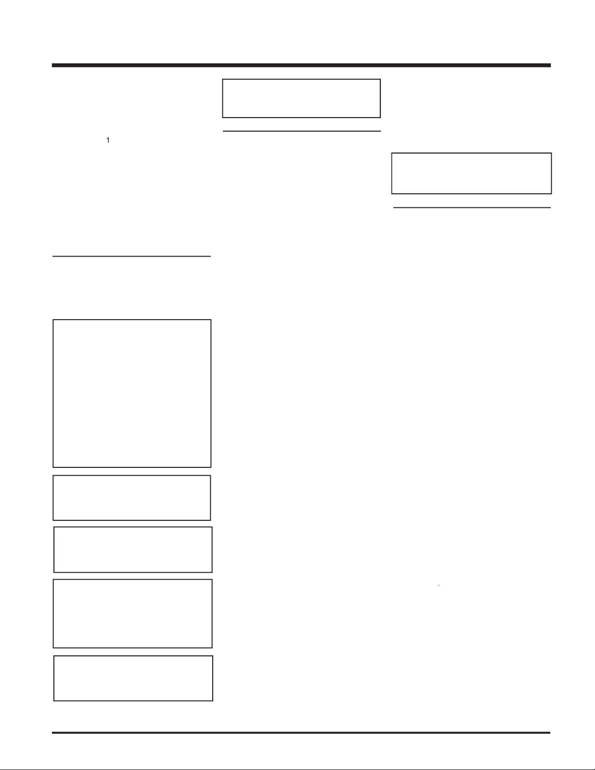
AERATION
ADJUSTMENT
3/16" Natural Gas
1/2" Propane
Carbon will be produced if air shutter
®
Installer at the time of
Adjustment Wire: push to close or
pull to open aeration cap.
IMPORTANT
be operated with the tension springs
WITHOUT THE GLASS FRONT IN
To ignite or reignite the pilot,
you must fi rst release the ten-
sion springs below the door.
Page 35

®
G36D Zero Clearance Direct Vent Gas Fireplace
Always turn off the gas valve before cleaning.
Clean appliance and door with a damp
The heater is fi nished in a heat resistant
®
uses StoveBright
Gas Inlet
TURN OFF GAS
APPLIANCE
YOUR SAFETY
READ BEFORE LIGHTING
READ BEFORE LIGHTINGYOUR SAFETY
LIGHTING INSTRUCTIONS
f th e fl ame s wi tc h.
f al l el ect ri c po we r to th e ap pl ia nce i f se rv ic e is to b e pe rform ed .
Yo
f th e pi lot d ur in g pr olo ng ed n on u se pe ri od s to cons er ve f ue l.
Wa
way
when
A)
which
When
follow
for
fl
DO IF
YOU SMELL
GAS
from
fi
will
water
vapors
DO NOT REMOVE THIS INSTRUCTION PLATE
W
ARNING:
you
with
ANSI Z223.1/NFP
B149.1. (Australia:
B149.1. (Australia:
AG601, New Zealand: NZS 5261
AG601, New Zealand: NZS 5261
FOR UNITS NOT EQUIPPED WITH ELECTRIC SPARK BOXES:
FOR ALL PROPANE UNITS AND UNITS EQUIPPED WITH ELECTRIC SPARK BOXES:
Gas Inlet
position.
way
fl
BURNER
VEILLEUSE
APPLIANCES
from your gas appliance. This is perfectly normal
will expand and contract at slightly different
for steel fi reboxes.
As the gas control valve turns ON and OFF, a
Page 36

®
G36D Zero Clearance Direct Vent Gas Fireplace
Make a periodic check of burner for proper
The appliance and venting system must be
Do not use this appliance if any part has been
water.
Verify operation after servicing.
Check the Venting System for corrosion in
Remove the Cap, and shine a fl ashlight
Ch e ck for evi d enc e s o f e xce ssi v e
Ins pect jo ints, to verify that no pipe
Open the bottom louvers.
Loosen the thermocouple or thermopile with
Disconnect thermocouple by loosening
Drop the thermocouple or thermopile down
from the bracket and pull it out of the unit.
Reinstall the new ones in reverse order.
# 936-155).
Your UltraGlow
®
fi replace is supplied with high
withstand the highest heat that your unit will
when hot.
®
dealer only, and follow our step-by-
WARNING
with the glass panels removed, cracked
Page 37

®
G36D Zero Clearance Direct Vent Gas Fireplace
Undo the pilot tube from the valve with a
7/16" wrench.
Undo the quick drop out thermocouple nut
Remove the Piezo ignitor wire and push
Undo the "gas out" fl are nut with a 13/16"
wrench.
wrench.
Remove the 4 Phillips head screws from
Attach the valve to the valve bracket with
Reconnect the "gas out" fl are fi tting with an
Reconnect the "gas out" fl are nut with a
13/16" wrench.
Reconnect the quick drop out thermocouple
Reconnect the pilot tube nut with a 7/16"
wrench.
Scrape off the old gasket from the fl oor of the
Install a new gasket and reinstall the valve
performance.
Reinstall the 12 hold down screws.
Hook up the 2 TP and 2 TH wires to the
Reinstall the bottom brick panel and the
front log stand.
Hook up the gas line and check for gas
for leak testing.)
Fire up the unit temporarily
Check the manifold pressure.
Reinstall the logs and base panels as
Close the door and replace the louvers.
Fire up the unit again and check for proper
Remove louvers.
Open and remove the fl ush door.
Remove logs.
Remove the burner assembly by removing
Remove the rear log stand by removing the
Lift out the bottom base panel.
Disconnect the inlet gas line.
Disconnect the 2 TP wires and the 2 TH
wires from the valve.
Verify proper operation
Page 38

®
G36D Zero Clearance Direct Vent Gas Fireplace
Part # Description
910-882 Wire-Harness-Valve to Burner
331-917 Fan & Speed Control Assy
(120 Volts) Optional
918-515 Manual
290-969 Conversion Kit - NG to LP
Page 39

®
G36D Zero Clearance Direct Vent Gas Fireplace
Part # Description
786-574/P Valve Assy - Natural Gas
786-576/P Valve Assy - Propane
910-380 Valve - S.I.T. - Propane
910-039 Pilot Assy - S.I.T. - 3 Flame LP
904-430 Orifi ce #42 - Natural Gas
904-345 Orifi ce #53 - Propane
936-170 Orifi ce Gasket
Page 40

®
G36D Zero Clearance Direct Vent Gas Fireplace
510-947 Flush Glass Trim (Set) - Steel
510-932 Flush Glass Trim (Set) - Gold
Part # Description
Page 41

®
G36D Zero Clearance Direct Vent Gas Fireplace
___________________________________________________
___________________________________________________
___________________________________________________
___________________________________________________
___________________________________________________
___________________________________________________
___________________________________________________
___________________________________________________
___________________________________________________
___________________________________________________
___________________________________________________
___________________________________________________
Page 42

®
G36D Zero Clearance Direct Vent Gas Fireplace
___________________________________________________
___________________________________________________
___________________________________________________
___________________________________________________
___________________________________________________
___________________________________________________
___________________________________________________
___________________________________________________
___________________________________________________
___________________________________________________
___________________________________________________
___________________________________________________
Page 43

®
G36D Zero Clearance Direct Vent Gas Fireplace
®
®
products, are designed with reliability and simplicity in mind. In addition, our internal Quality Assurance Team carefully
®
®
is pleased to extend this one year warranty to the original purchaser
®
®
product. This warranty is not transferable.
Any part or parts of this unit which in our judgement show evidence of such defects will be repaired or replaced at FPI's option, through an accredited
if requested.
workmanship from unauthorized service persons or dealers.
At all times FPI reserves the right to inspect product in the fi eld which is claimed to be defective.
All claims must be submitted to FPI by authorized selling dealers. It is essential that all submitted claims provide all of the necessary information
At no time will FPI be liable for any consequential damages which exceed the purchase price of the unit. FPI has no obligation to enhance or modify
warranty policy.
Any unit which shows signs of neglect or misuse is not covered under the terms of this warranty policy.
Any alteration to the unit which causes sooting or carboning that results in damage to the interior / exterior facia is not the responsibility of FPI.
Page 44

G36D Zero Clearance Direct Vent Gas Fireplace
______________________________________________
___________________________________________________________________
___________________________________________________________
___________________________________________________________
______________________________________________________
__________________________________________________________
®
®
online at
© Copyright 2005, FPI Fireplace Products International Ltd. All rights reserved.
 Loading...