

Page 1
•
Ceiling Fa n Ow n e r ’s Ma n u a l
•
Style that revolves around you.
•De u C e Hu g g e r •
WARNING: Read and follow these instructions carefully and be mindful of all warnings shown throughout.
10/09
第 1 页,共 12 页2009-11-11
Page 2
ge n e r a l in s t a l l a t i O n & Op e r a t i O n in s t r u C t i O n s
I m p o r t a n t Sa f e g u a r d S :
1. To ensure the success of the installation, be sure to read the instructions and review the diagrams thoroughly before
beginning.
2. To avoid possible electrical shock, be sure electricity is turned off at the main power box before wiring. All electrical
connections must be made in accordance with local codes, ordinances and/or the National Electric Code. If you are
unfamiliar with the methods of installing electrical wiring and products, secure the services of a qualified and licensed
electrician as well as someone who can check the strength of the supportive ceiling members and make the proper
installation(s) and connections.
3. Make sure that your installation site will not allow rotating fan blades to come in contact with any object. Blades should
be at least 7 feet from floor.
4.
When mounting
on a ceiling outlet box, an approved box UL listed as “suitable for fan support” is required.
The box and its supporting members must be able to support the moving weight of the fan’s listed weight.
The box must not be able to twist or work loose. Installation on a concrete ceiling should be performed by
qualified personnel.
5. Blades should be attached after motor housing is hung and in place. Fan motor housing should be kept in the carton
until ready to be installed to protect its finish. If you are installing more than one ceiling fan, make sure that you do
not mix fan blade sets, as each blade is part of a weighted set.
6. After making electrical connections, spliced conductors should be turned upward and pushed carefully up into outlet
box. The wires should be spread apart with the common conductor and the grounding conductor on one side of the
outlet box, and the “HOT” wires on the other side.
7. Electrical diagrams are for reference only. Light kits that are not packed with the fan must be UL listed and should be
installed per the light kit’s installation instructions.
8. After fan is completely installed, check to make sure that all connections are secure to prevent fan from falling and/or
causing damage or injury.
9. The fan can be made to work immediately after installation - the bearings are adequately charged with grease so that,
under normal conditions, further lubrication should not be necessary for the life of the fan.
10. The fan should be turned off and allowed to stop rotating before reversing fan direction.
ATTENTION: Under the Energy Policy Act of 2005, federal regulations require all ceiling fans with light kits manufactured
or imported after Jauary 1, 2009, to limit the total wattage consumed by the light kit to 190 watts. Therefore, this product
is equipped with a 190W limiting device. If lamping exceeds 190 watts, the light kit will shut off automatically until the
proper wattage of bulbs are installed. Reset the light kit by turning it off, replacing the bulbs with the correct wattage, and
then turning the light kit back on.
1
第 2 页,共 12 页2009-11-11
Page 3
Warnings:
• Disconnect power by removing fuse or turning off circuit breaker before installing the fan.
• Support directly from building structure.
• To reduce the risk of fire, electric shock, or personal injury, mount to outlet box marked “acceptable for
fan support” and use mounting screws provided with the outlet box. Most outlet boxes commonly used for the
support of lighting fixtures are not acceptable for fan support and may need to be replaced. Consult a qualified
electrician if in doubt.
• To reduce the risk of fire, electrical shock, or personal injury, only use this fan with an appropriate speed control
device designed for use with ceiling fans if you choose a wall control. DO NOT USE INCANDESCENT LIGHT
DIMMER. Do not use this fan with any transformer type fan speed control device.
• To reduce the risk of personal injury, do not bend the blade arms when installing them, balancing the blades or
cleaning the fan. Do not insert any objects(s) between rotating fan blades.
NOTE: The important precautions, safeguards and instructions appearing in this manual are not meant to cover all
possible conditions and situations that may occur. It must be understood that common sense, caution and carefulness
are factors which cannot be built into this product. These factors must be supplied by the person(s) installing, caring
for, and operating the unit.
tO O l s a n D Ma t e r i a l s re q u i r e D
Thank you for choosing a Regency Ceiling Fan. You have chosen the best!
Your new ceiling fan has been designed to provide many years of service and enjoyment.
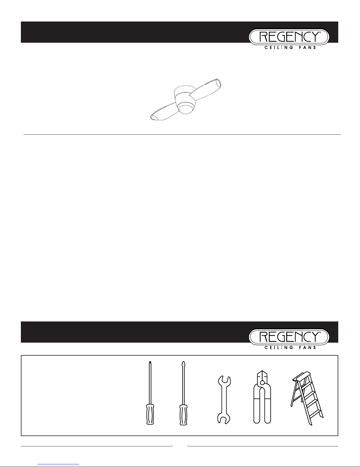
• Phillips screwdriver
• Blade screwdriver
• Wrench or pliers
• Wire cutter
• Stepladder
• Wiring supplies as required by
electrical code
2
iM p O r t a n t sa F e t y pr e C a u t i O n s
第 3 页,共 12 页2009-11-11
Page 4
第 4 页,共 12 页2009-11-11
Page 5
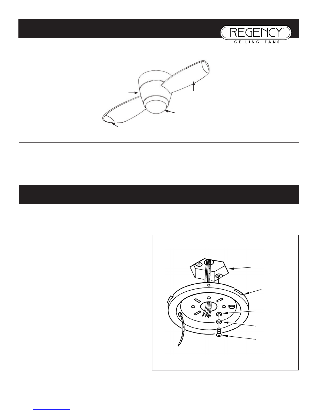
pr e p a r a t i O n
4
Blade
Blade Tip
Light / Cover
Fan
Housing
pr e p a r a t I o n :
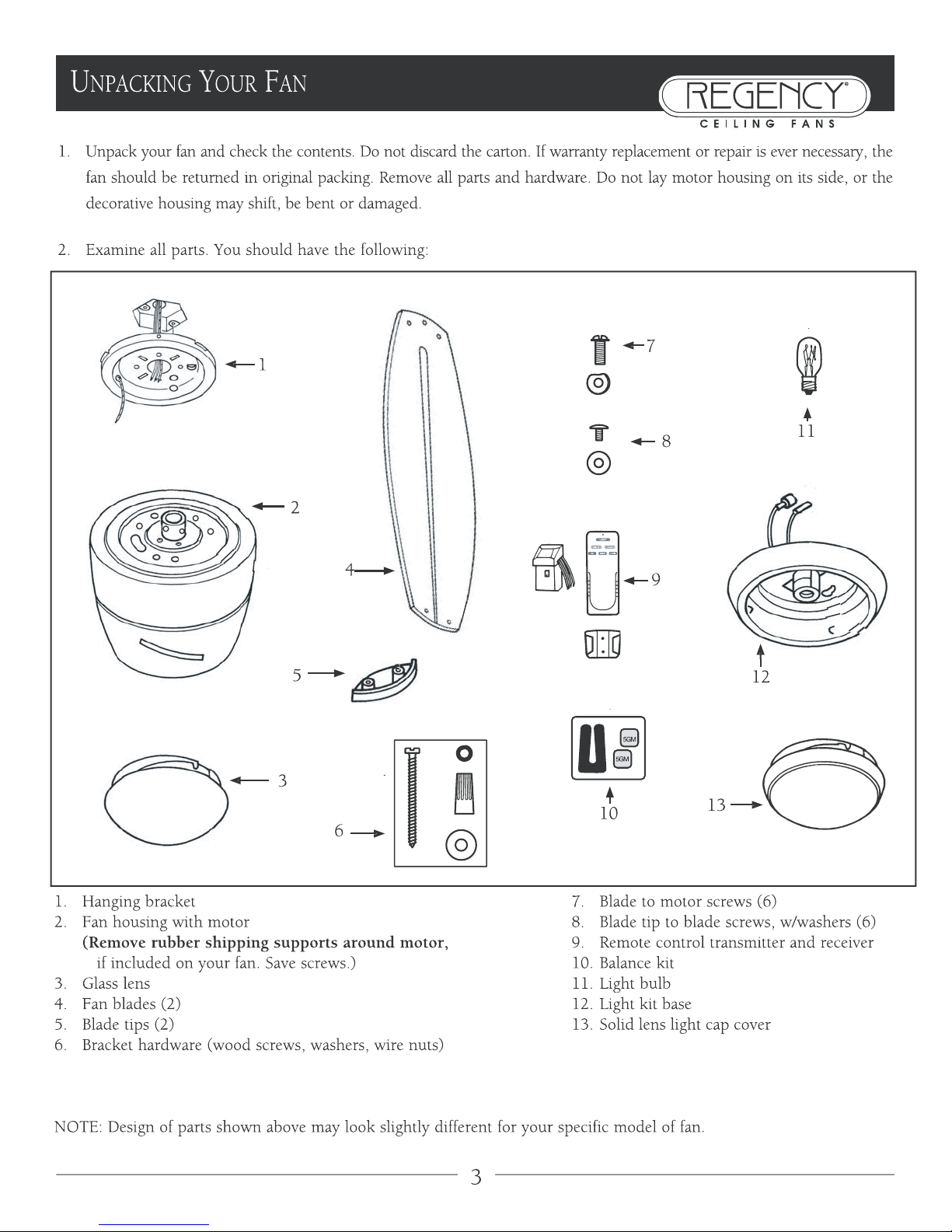
Verify that you have all parts before beginning the installation. Check foam insert closely for missing parts. Remove motor
from packing. To avoid damage to finish, assemble motor on soft padded surface or use the original foam inset in motor box.
Do not lay fan on its side as this could result in shifting of motor in decorative enclosure.
Caution: To avoid possible electric shock, be sure electricity is turned off at the main power box before wiring. All wiring
must be in accordance with National and Local Electrical Codes and the ceiling fan must be grounded as a precaution against
possible electrical shock.
in s t a l l i n g t H e Ha n g i n g Br a C k e t
1. Locate ceiling joist where fan is to be mounted, being
sure location agrees with the requirements in the
minimum clearance section of this guide. Wood joist
must be sound and of adequate size to support 35 lbs.
(See Page 1, Items 3 and 4)
2. If not already present, mount a UL listed outlet
box marked “suitable for fan support”, following
the instructions provided with the outlet box. The
outlet box must be able to support a minimum of 35
pounds.
3. Attach hanging bracket to outlet box using screws
provided with the outlet box.
Electric Box
Mtg. Plate
Split Washer
Flat Washer
Mtg. Screw
第 5 页,共 12 页2009-11-11
Page 6
in s t a l l i n g t H e Fa n
5
WARNING: To avoid damaging the blades, do not install
them onto fan until fan is fastened to ceiling.
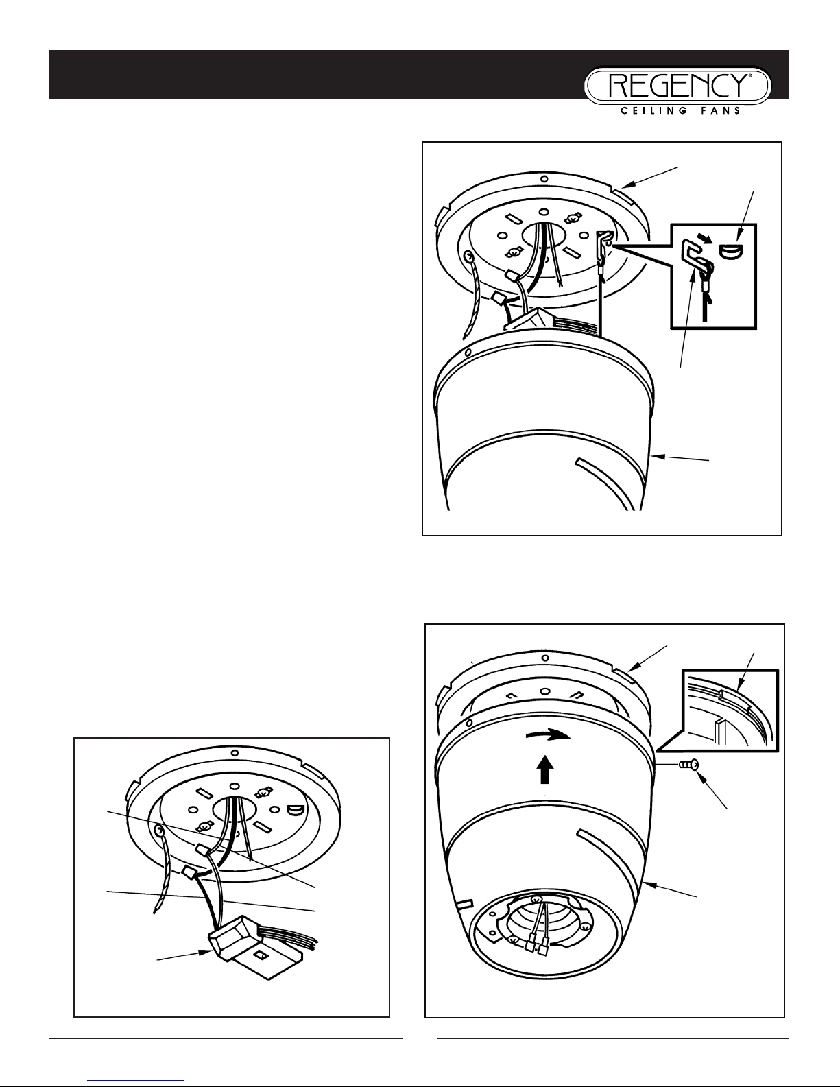
1. Carefully support the fan body (motor) in its styrofoam
packing with the top (where the wires come out) facing
upward.
2. Lift fan body to the hanging bracket and attach the
installation tether from the fan body to the mounting
plate for easier installation.
NOTE: The installation tether is a tool to assist during the
installation of the fan. It is not intended to be the only
means of supporting the fan. Care should be taken until the
fan is securely attached to the mounting plate. (Fig. 1).
Attach the Receiver (Fig. 2)
3. Connect the white wire from the outlet box to the white
wire on AC In side of the receiver.
4. Connect the black wire from the outlet box to the black
wire on the AC In side of the receiver.
5. Make wire connections (refer to page 6 “Electrical
Connections”.)
6. Lift fan up to the hanging bracket aligning the keys on the
fan body with the mounting plate. Rotate clockwise a 1/4
turn until the screw holes in the fan body align with the
holes in the mounting plate. Attach the 3 screws to secure
the fan to the mounting plate. (Fig.3).
Locking Tab
Mtg. Screw
Fan Body
Fan Body
Mtg. Plate
Tether Hole
Installation
Tether
Fig. 1
Fig. 3
White Wire
Receiver
Black
Wire
Black
Wire
Fig. 2
第 6 页,共 12 页2009-11-11
Page 7
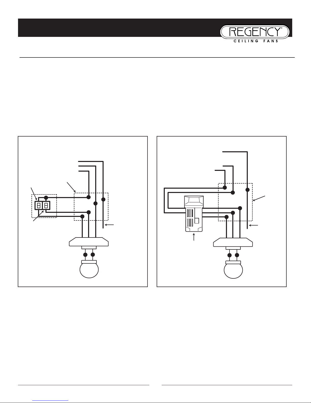
el e c t r I c a l co n n e c t I o n S : Be sure electricity is turned off at the main power box before wiring
el e C t r i C a l CO n n e C t i O n s
6
Wire Connections:
Four wires are connected to the fan.
Black – this is the “hot” power to run fan.
White – this is the “common” power to run fan and light.
Blue – this is the “hot” power for light kit.
Green – ground wire (on bracket).
Wiring
Light
BLK
BLUE
WH
Fan and light controlled by
Ground to
BLUE
BLK
WH
Fan
Light
Power lines
GROUND
BLK
WH
GREEN
Fan
independent approved speed/light wall controller
120V
box
switch
bracket
mounting
switch
WH
Wiring
WH
BLUE
BLK
Fan and light controlled by
Ground to
BLUE
BLK
WH
Fan
Light
Power lines
GROUND
BLK
WH
GREEN
remote transmitter.
120V
box
Receiver
downrod
WH
BLK
WH
*
第 7 页,共 12 页2009-11-11
Page 8
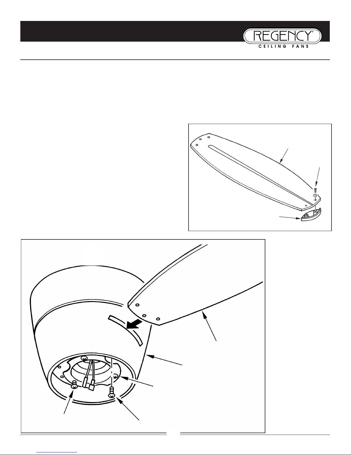
1. Place fiber washer on screw. Insert this assembly through the blade and start the screw into the blade tip. Repeat this
procedure without tightening the screw until all 3 screws have been started into the blade tip (Fig. 1).
2. Tighten each screw starting with center screw.
3 Insert the blade into the motor housing and fasten blade assembly to motor with provided screws and metal lock
washers (Fig. 2). Repeat procedure for the other blade. Make sure screws are TIGHT! Loose motor screws can contribute
to unnecessary humming and wobbling during operation.
7
Bl a D e at t a C H M e n t
Bl a d e at t a c h m e n t :
Blade Assembly
Blade To Motor Screw
Fan Motor
Fig. 2
Blade
Blade Tip
Blade Tip Screw
Fig. 1
NOTE: Cordless power screwdrivers are NOT recommended,
as they tend to strip the heads of the screws and usually will
not fully compress the spring washers on the motor screws.
Use a large flat blade screwdriver for final tightening to fully
compress the spring washers. This will help ensure proper
alignment of the blades and noise-free, wobble-free running.
Fan Housing
Blade To Motor Screw
第 8 页,共 12 页2009-11-11
Page 9
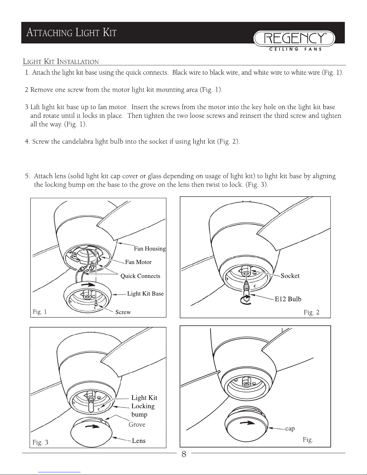
NOTE: If using fan with solid light kit cap cover, do not install bulbs, just install a cap instead(Fig.4)
第 9 页,共 12 页2009-11-11
Page 10
9
re M O t e CO n t r O l
ge n e r a l In f o r m a t I o n
NOTE: For use with a standard remote control.
Multiple code choices are included with your fan’s remote control in case:
• you have more than one remote control fan and want them to respond only to their own remote control
• you have other radio controlled devices in your home that may interfere with the fan remote control (i.e. garage door
opener)
• you experience radio interference on a chosen frequency (code setting)
Se t -u p a n d op e r a t I n g In S t r u c t I o n S
Setting the code:
This unit has 16 different code combinations. To set the code, perform these steps:
1. Setting the code on the TRANSMITTER:
a. Remove battery cover.
b. Slide code switches to your choice of ON or OFF position. Use a small screwdriver or ball point pen to slide
each switch firmly up or down.
c. Install 9v battery (not included).
d. Replace battery cover on transmitter.
2. Setting the code on the RECEIVER:
a. Locate the code switches on the bottom of the remote receiver.
b. Slide code switches to the SAME POSITIONS as set on your transmitter.
Operating buttons on the transmitter:
HI – fan high speed
MED – fan medium speed
LOW – fan low speed
FAN OFF – fan speed off
LIGHT – light brightness and off
FOR/REV – forward or reverse (down or up) air flow
• The light function is controlled by pressing the light button. Hold button down to increase or decrease light brightness.
Tap button quickly to turn light off or on.
• Keep pressing the button for more than one second to dim the light and vary it cyclically from dim to bright and back again.
• The light button has auto return (memory function), so it will stay at the same brightness as the last time it was turned off.
• Range of the transmitter is approximately 25 ft.
第 10 页,共 12 页2009-11-11
Page 11
op e r a t I n g B u t t o n S o n t h e tr a n S m I t t e r
HI – fan high speed
MED – fan medium speed
LOW – fan low speed
FAN/OFF – fan speed off
LIGHT – light brightness and off function for uplight
FOR/REV – forward and reverse
• The light functions are controlled by pressing the light button. Hold button down to
increase or decrease light brightness. Tap button quickly to turn light off or on.
• Keep pressing the button for more than one second to dim the light and vary it
cyclically from dim to bright and back again.
• Range of the transmitter is approximately 25 ft.
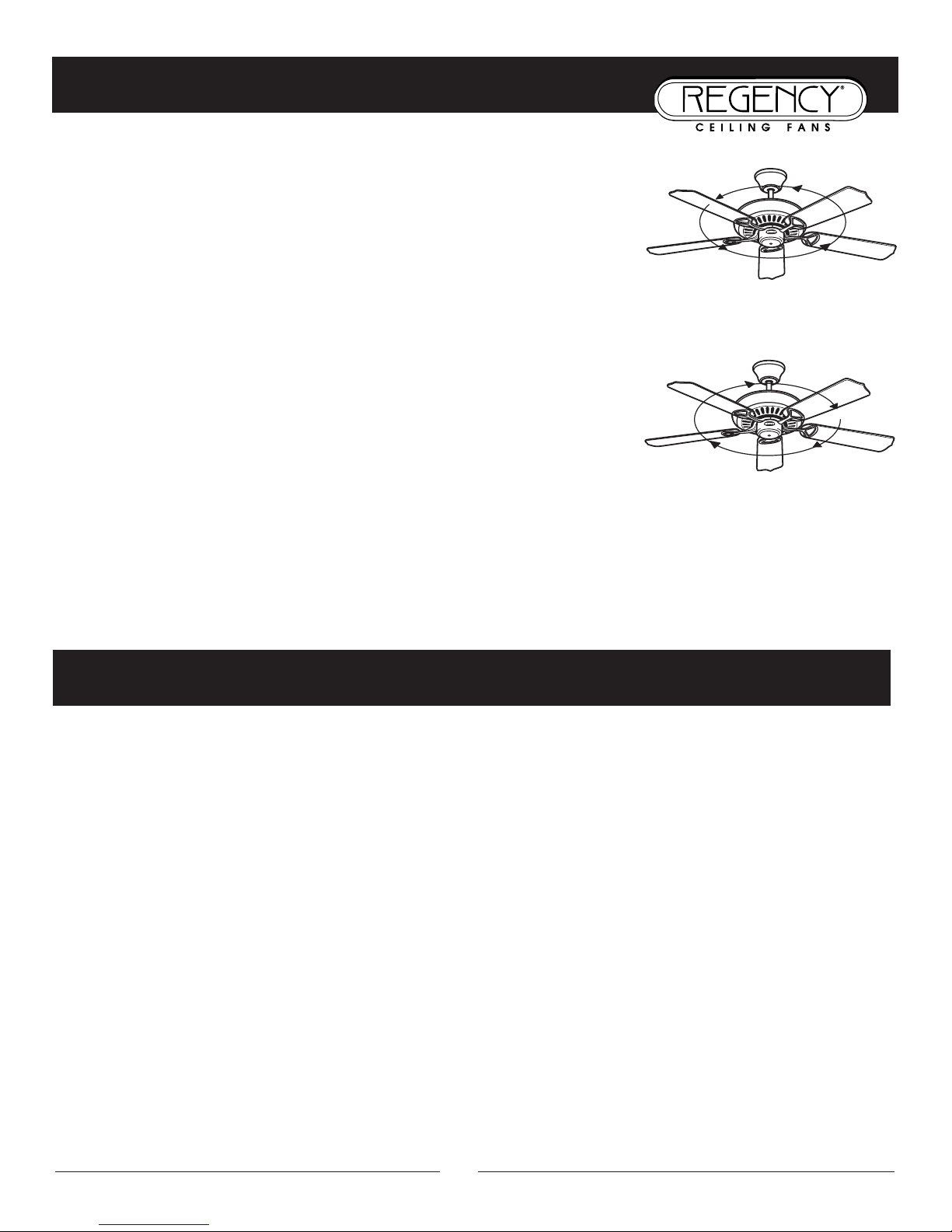
• Forward/Reverse Direction:
Forward is a counterclockwise rotation of the blades when viewed from beneath the
fan. This will create a downward breeze that can be felt below the fan. This is the
normal direction for the fan to run when the weather is warm.
Reverse (clockwise) will draw air up through the blades and towards the ceiling, down
the walls, and into the living space during the cooler months.
IMPORTANT: To prevent damage or cause injury, be sure that fan is switched to off and blades have stopped moving
completely before attempting to change direction of rotation.
10
Op e r a t i O n
WARM MONTHS
Forward (counterclockwise)
COOL MONTHS
Reverse (clockwise)
1. If fan will not start: Check main and branch circuit breakers and/or fuses. Check line wire connections to fan and switch
housing wiring. Make sure forward/reverse switch is set to one or the other position, not stuck in between.
2. If fan is noisy: Check and make sure that all screws in motor housing are snug (but not over tight). Check that the screws
securing blade brackets to the motor are tight. Check that wire connectors in switch housing are not rattling against each other
or the interior wall of the switch housing. Check that all glassware is finger tight and that bulb(s) are well held in the sockets,
if a light kit is used. Check that the canopy is firmly attached to hanging bracket and not vibrating against ceiling.
3. If fan wobbles: Check that all blades are firmly screwed into blade arms. Check that all blade arms are firmly secured to the
motor. Make sure that the light kit (if present) is firmly attached to switch housing and that all glassware and shades are
fastened properly. Wobble can also result from even the smallest deviations in distance from blade tip to blade tip - if
measurements from blade tip to blade tip are not equal, loosen screws connecting blade to bracket one at a time and adjust
blade(s) so that distances are equal. Interchanging adjacent blades may redistribute mass and result in smoother operation.
Blade arms can be bent slightly to restore same pitch to all blades if a blade is different than the other blades when viewed
edge on.
tr O u B l e s H O O t i n g - in Ca s e O F Di F F i C u l t y
第 11 页,共 12 页2009-11-11
Page 12

tH a n k y O u F O r p u r C H a s i n g a re g e n C y Ceili n g Fa n .
Write to us at:
Regency Ceiling Fans
P.O. Box 730
Fenton, MO 63026
For additional troubleshooting tips,
visit us on the Web at: www.regencyfans.com
10/09 Regency Ceiling Fans
Periodic cleaning of your new ceiling fan is about the only maintenance that is needed. Only use a soft brush or lint free cloth
to avoid scratching the finish. DO NOT use water when cleaning your ceiling fan. It could damage the motor or the wood
blades, and/or create the possibility of electrical shock.
NOTE: Periodically it may be necessary to re-tighten blade screws to prevent clicking or humming sound during
operation. This is especially true in climates with broad temperature and humidity ranges and in fans with painted or high gloss
blades.
NOTE: When dusting the blades, you must support the blade to prevent bending - no pressure should be applied to
the blades.
Ca r e a n D Cl e a n i n g
第 12 页,共 12 页2009-11-11
 Loading...