

Page 1
•
CEILING FAN OWNER’S MANUAL
•
5/03
• I/O “THE INDOOR/OUTDOOR FAN” •
WARNING: Read and follow these instructions carefully and be mindful of all warnings shown throughout.
Page 2

Page 3

GENERAL INSTALLATION & OPERATION INSTRUCTIONS
I
I
MMPPOORRTTAANNT
TToo eennssuurree tthhee ssuucccceessss ooff tthhee iinnssttaallllaattiioonn,, bbee ssuurree ttoo rreeaadd tthhee iinnssttrruuccttiioonnss aanndd rreevviieeww tthhee ddiiaaggrraammss tthhoorroouugghhlly
1.
bbeeffoorree bbeeggiinnnniinngg.
TToo aavvooiidd ppoossssiibbllee eelleeccttrriicc sshhoocckk,, bbee ssuurree eelleeccttrriicciittyy iiss ttuurrnneedd ooffff aatt tthhee mmaaiinn ppoowweerr bbooxx bbeeffoorree wwiirriinngg..
2.
connections must be made in accordance with local codes, ordinances and/or the National Electric Code. If you are
unfamiliar with the methods of installing electrical wiring and products, secure the services of a qualified and
licensed electrician as well as someone who can check the strength of the supportive ceiling members and make
the proper installation(s) and connections.
3. Make sure that your installation site will not allow rotating fan blades to come in contact with any object. Blades
should be at least 7 feet from floor when fan is operating.
4. The fan should be mounted on a ceiling outlet box, an approved box UL listed as
required. The box and its supporting members must be able to support the moving weight of the fan (at least
35lbs.). The box must not be able to twist or work loose. Installation on a concrete ceiling should be performed
by qualified personnel.
S
T
S
AAFFEEGGUUAARRDDS
:
S
:
.
All electrical
““ssuuiittaabbllee ffoorr ffaann ssuuppppoorrt
t
” is
y
5. Blades should be attached after
ton until ready to be installed to protect its finish. If you ar
car
that you do not mix fan blade sets, as each blade is part of a weighted set.
6. After making electrical connections, spliced conductors should be turned upward and pushed carefully up into
outlet box. The wires should be spread apart with the common conductor and the grounding conductor on one
side of the outlet box, and the “HOT” wir
7. Electrical diagrams are for reference only.
After fan is completely installed, check to make sur
8.
and/or causing damage or injury.
The fan can be made to work immediately after installation - the bearings ar
9.
that, under nor
10. The fan should be turned off and allowed to stop rotating before reversing fan direction.
mal conditions, further lubrication should not be necessary for the life of the fan.
motor housing is hung and in place. Fan motor housing should be kept in the
e installing more than one ceiling fan, make sure
es on the other side.
e that all connections ar
e secur
e adequately char
e to prevent fan from falling
ged with gr
ease so
1
Page 4
IMPORTANT SAFETY PRECAUTIONS
Thank you for choosing a Regency Ceiling Fan.
You have chosen the best!
Your new ceiling fan has been designed to provide
many years of service and enjoyment.
W
W
AARRNNIINNGGS
DDiissccoonnnneecctt ppoowweerr bbyy rreemmoovviinngg ffuussee oorr ttuurrnniinngg ooffff cciirrccuuiitt bbrreeaakkeerr bbeeffoorree iinnssttaalllliinngg tthhee ffaann aanndd//oorr ooppttiioonnaall lliigghhttiinngg.
*
* To reduce the risk of fire, electric shock, or personal injury, mount to outlet box marked “acceptable for fan support”
and use mounting screws provided with the outlet box. Most outlet boxes commonly used for the support of
lighting fixtures are not acceptable for fan support and may need to be replaced. Consult a qualified electrician
if in doubt.
* To reduce the risk of fire, electrical shock, or personal injury, only use this fan with an appropriate speed control
device designed for use with this ceiling fan.
* To reduce the risk of personal injury, do not bend the blade arms when installing or balancing the blades or cleaning
the fan. Do not insert any objects between r
NNOOTTEE:
TThhee iimmppoorrttaanntt pprreeccaauuttiioonnss,, ssaaffeegguuaarrddss aanndd iinnssttrruuccttiioonnss aappppeeaarriinngg iinn tthhiiss mmaannuuaall aarree nnoott mmeeaanntt ttoo ccoovveerr aalll
ppoossssiibbllee ccoonnddiittiioonnss aanndd ssiittuuaattiioonnss tthhaatt mmaayy ooccccuurr.. IItt mmuusstt bbee uunnddeerrssttoooodd tthhaatt ccoommmmoonn sseennssee,, ccaauuttiioonn,, aannd
ccaarree aarree ffaaccttoorrss wwhhiicchh ccaannnnoott bbee bbuuiilltt iinnttoo tthhiiss pprroodduucctt.. TThheessee ffaaccttoorrss mmuusstt bbee ssuupppplliieedd bbyy tthhee ppeerrssoonn((ss)
iinnssttaalllliinngg,, ccaarriinngg ffoorr aanndd ooppeerraattiinngg tthhee uunniitt.
:
S
:
otating fan blades.
:
.
.
l
d
)
TOOLS AND MATERIALS REQUIRED
• Phillips scr
• Blade screwdriver
ench or pliers
r
• W
• Wire cutter
• Stepladder
iring supplies as required by
• W
electrical code
ewdriver
2
Page 5
UNPACKING YOUR FAN
1
7
8
3
9
6
2
4
5
10
11
REV
MED
OFF
HI
LOW
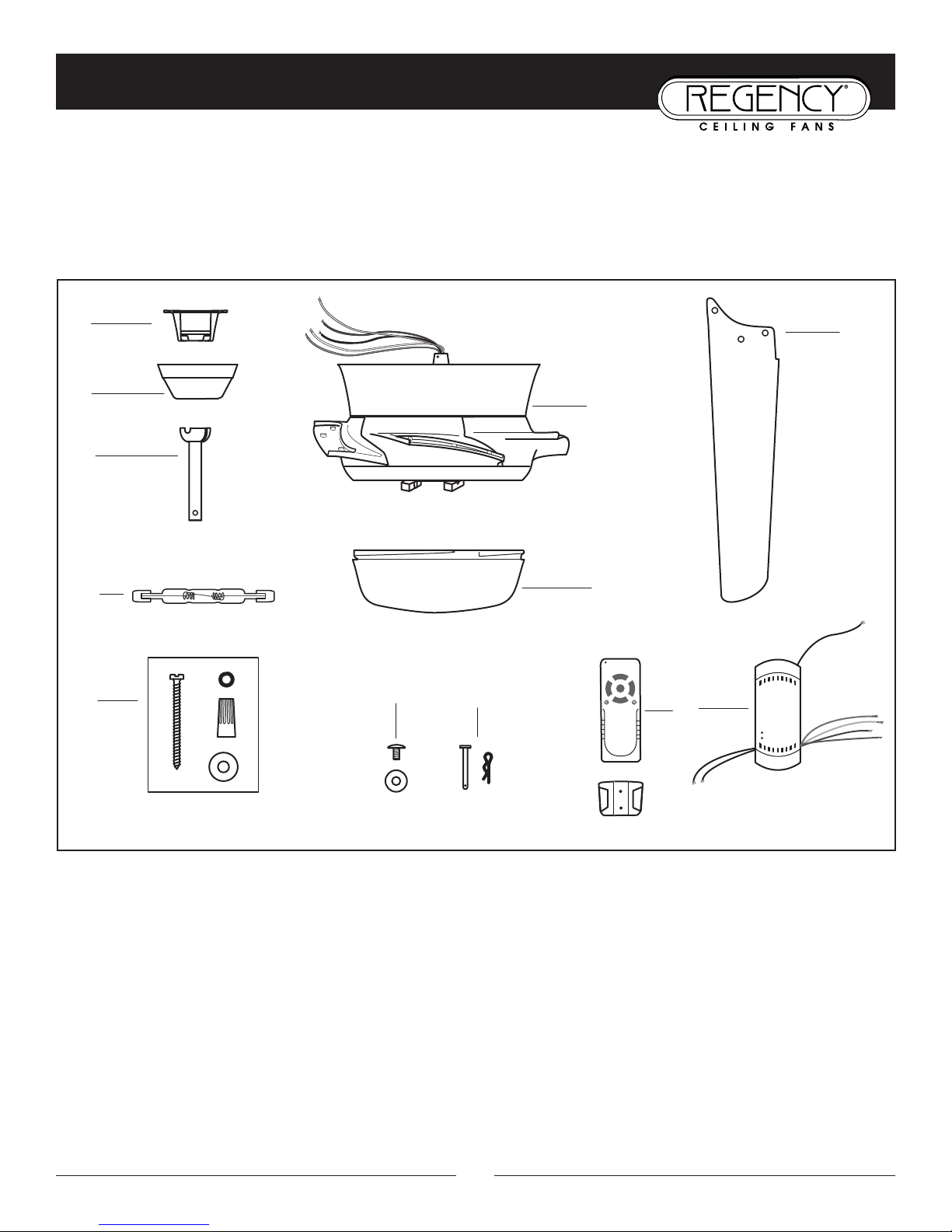
1. Unpack your fan and check the contents. Do not discard the carton. If warranty replacement or repair is ever necessary,
the fan should be returned in original packing. Remove all parts and hardware. Do not lay motor housing on its
side, or the decorative housing may shift, be bent or damaged.
2. Examine all parts. You should have the following:
1. Mounting bracket
2. Ceiling canopy
3. Downrod/ball assembly
4. Fan housing with motor and blade arms
Blade ar
8.
Downr
9.
Remote contr
10.
Light bulb (100W “J” type)
11.
5. Shade
6. Fan blades (5)
7. Bracket hardware (wood screws, washers,
Recommended for uplight:
Four candelabra base (E12) 40W bulbs (not included)
wire nuts)
m to blade scr
od pin and cotter pin
ol transmitter and r
ews w/washers
eceiver w/wall holster
3
Page 6
PREPARATION
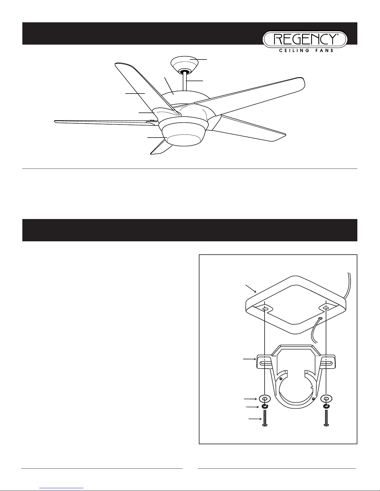
Ceiling Fan
Outlet Box
Hanger
Bracket
Outlet Box
Screw
Flat Washer
Spring Washer
Parts identification on assembled fan
Fan Housing
Blade
Blade Arm
Glass Shade
P
P
RREEPPAARRAATTIIOON
Verify that you have all parts before beginning the installation. Check foam insert closely for missing parts. Remove motor from
packing. To avoid damage to finish, assemble motor on soft padded surface or use the original foam inset in motor box. Do not
lay fan on its side as this could r
:
:
N
esult in shifting of motor in decorative enclosure.
Canopy
Downrod
INSTALLING THE MOUNTING BRACKET
CCaauuttiioonn::
tricity is turned off at the main power box before wiring. All
wiring must be in accor
Electrical Codes and the ceiling fan must be grounded as a
ecaution against possible electric shock.
pr
1. Locate ceiling area where fan is to be mounted, being sure
location agrees with the requirements in the minimum
clearance section of this guide. Mounting ar
sound and of adequate size to support 35 lbs. (p. 1, #3
and #4)
If not alr
2.
marked “suitable for fan support” following the instruc-
tions pr
be able to support a minimum of 35 pounds.
To avoid possible electrical shock, be sure elec-
dance with National and Local
ea must be
eady pr
ovided with the outlet box. The outlet box must
esent, mount a UL listed outlet box
3. Attach hanger bracket to outlet box using screws pro-
with the outlet box.
vided
4
Page 7
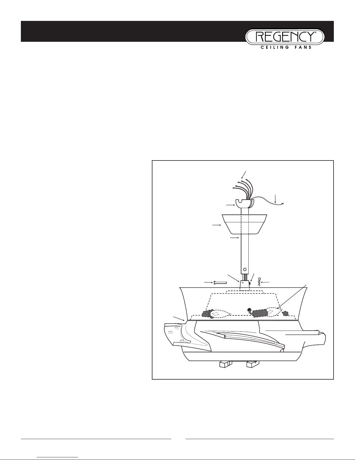
ASSEMBLY INSTRUCTIONS: DOWNROD AND CANOPY
Ground
Wire
H
ook-up Wires (5)
Ball
Security Screw and Lock Nut
Mounting Collar
Downrod Pin
Fan
Housing
Canopy
Downrod
(Optional extension shown)
40W Candelabra
Base Bulbs
Cotter Pin
1. Carefully support fan housing (motor) in its styrofoam packing with the mounting collar (where the wires come
out) facing upward.
2. Remove ball from downrod by loosening set screw in the side of the ball. Slide ball down and remove ball pin;
remove ball.
3. Feed the wires from top of fan through the end of the downrod, and set end of downrod into mounting collar so
the hole in the downrod lines up with the hole in the side of the mounting collar.
4. Insert downrod pin through holes in mounting collar and downrod and insert cotter pin to secure downrod.
5. Tighten security screw against downrod using a large flat blade screwdriver to ensure a tight fit against downrod.
Tighten lock nut to mounting collar.
NOTE: Fan has 6 feet of hook-up wire in case you
ires can be
are using a long extension downr
cut so only 8 inches or so extend beyond the top
of the downrod to make the electrical connections
easier and safer
.
od. W
6. Feed wires through canopy and slide
canopy over downrod to lay on top of fan.
It will be attached to ceiling later.
7. Feed wires through ball and slide ball over
downrod, past hole in the top end of downrod.
Insert ball pin (removed in Step 2), slide ball
up and tighten set screw to secure ball in
place.
8. Install 4 candelabra base bulbs (E12, 40w
max) in top sockets.
5
Page 8
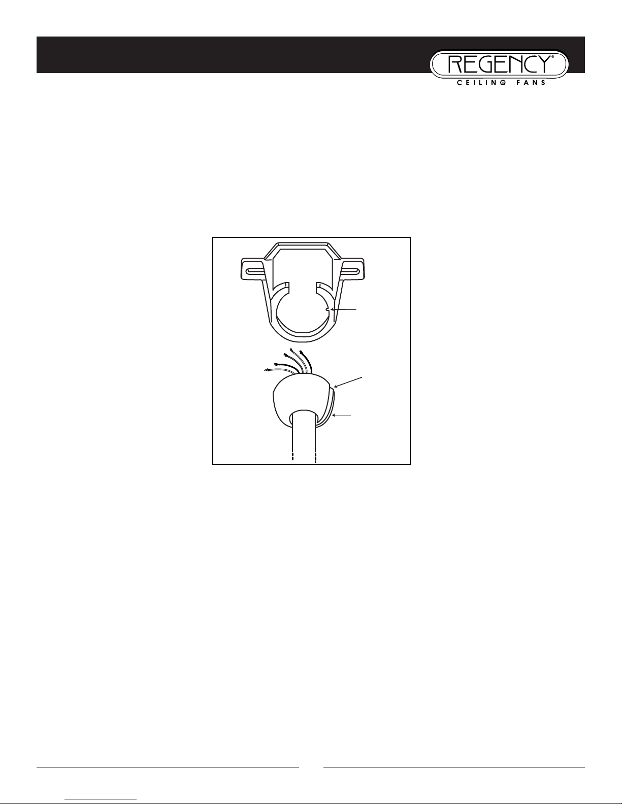
INSTALLING THE FAN
Hanger
bracket
tab
Ball
Ball slot
1. Lift ball/downrod/fan into hanger bracket opening. NOTE: The tab opposite hanger bracket opening should fit in
slot on ball.
2. Install remote control receiver (with codes set) and make wire connections, (refer to sections titled “Remote
Control” and “Electrical Connections”).
3. Slide canopy up and fasten to hanger bracket with screws provided.
WWAARRNNIINNGG:
If arms are bent or misaligned, e
:
To avoid damaging the blade arms and blades, do not install blades onto fan until fan is fastened to ceiling.
xcessive wobble may occur.
6
Page 9
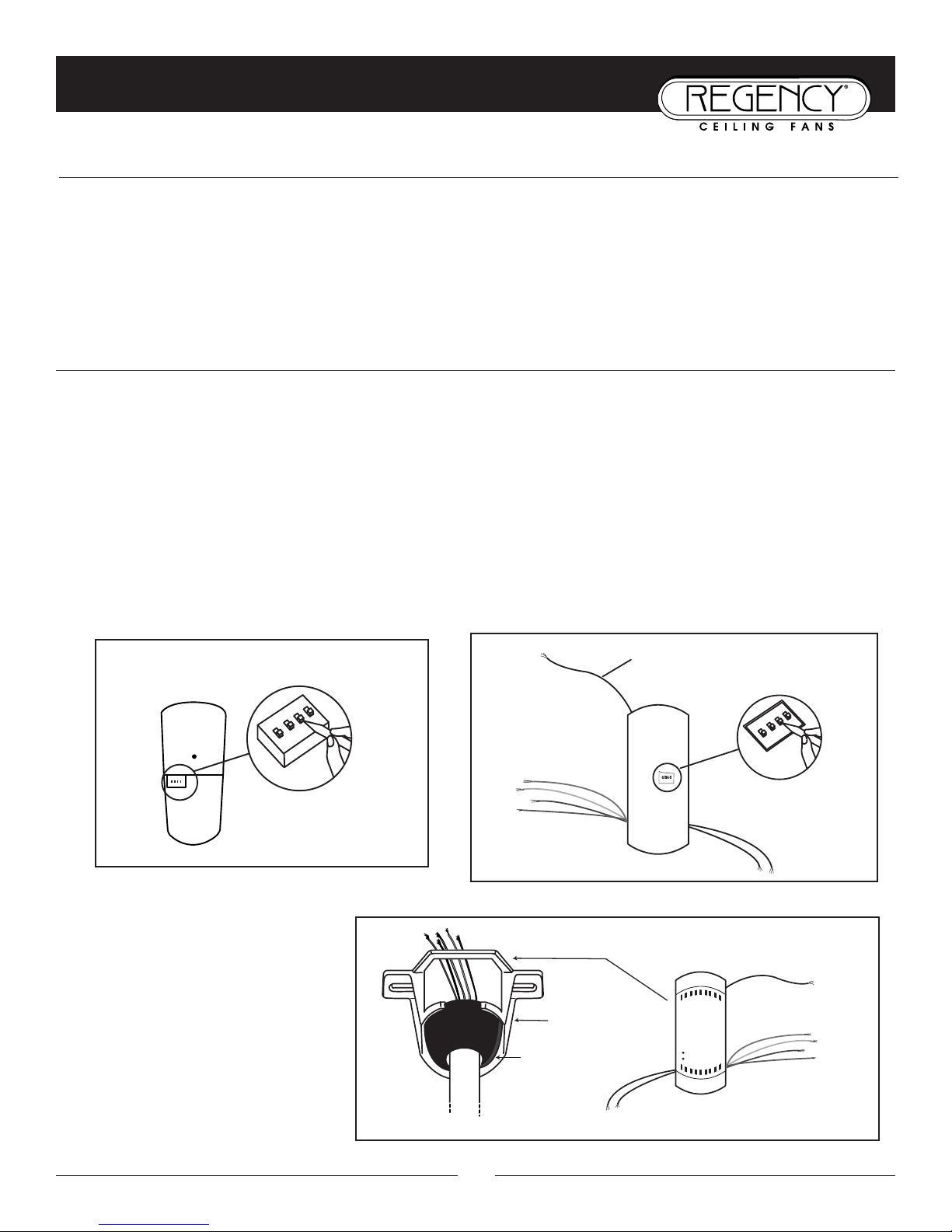
REMOTE CONTROL
1
234
1 2 3 4
ON
Code
Switches
TRANSMITTER
O
N ECE
Code
Switches
RECEIVER
1 2 3 4
ON
1
2
3
4
ON DIP
Antenna
Hanger
bracket
Ball
Receiver
G
G
EENNEERRAAL
I
L
I
NNFFOORRMMAATTIIOON
N
Multiple code choices are included with your fan’s remote control in case:
• you have more than one remote control fan and want them to respond only to their own remote control
• you have other radio controlled devices in your home that may interfere with the fan remote control (i.e. garage
door opener)
• you experience radio interference on a chosen frequency (code setting)
S
-
S
T
-
EET
UUPPAANND
SSeettttiinngg tthhee ccooddee:
This unit has 16 dif
D
O
O
:
PPEERRAATTIINNG
I
NNSSTTRRUUCCTTIIOONNS
S
I
G
ferent code combinations. To set the code, perform these steps:
1. Setting the code on the TRANSMITTER [Fig. 1]:
a. Remove battery cover.
Slide code switches to your choice of ON or OFF position. Use a small screwdriver or ball point pen to slide
b.
each switch firmly up or down.
c. Install 9v battery (not included).
d. Replace battery cover on transmitter
.
2. Setting the code on the RECEIVER [Fig. 2]:
a. Locate the code switches on the bottom of the remote receiver.
Slide code switches to the SAME POSITIONS as set on your transmitter
b.
.
After codes are set, install the receiver
in the space above the ball in the
hanger bracket [Fig. 3]. Be careful not
to pinch any of the receiver’s wires.
Fig. 1
Fig. 2
Fig. 3
7
Page 10
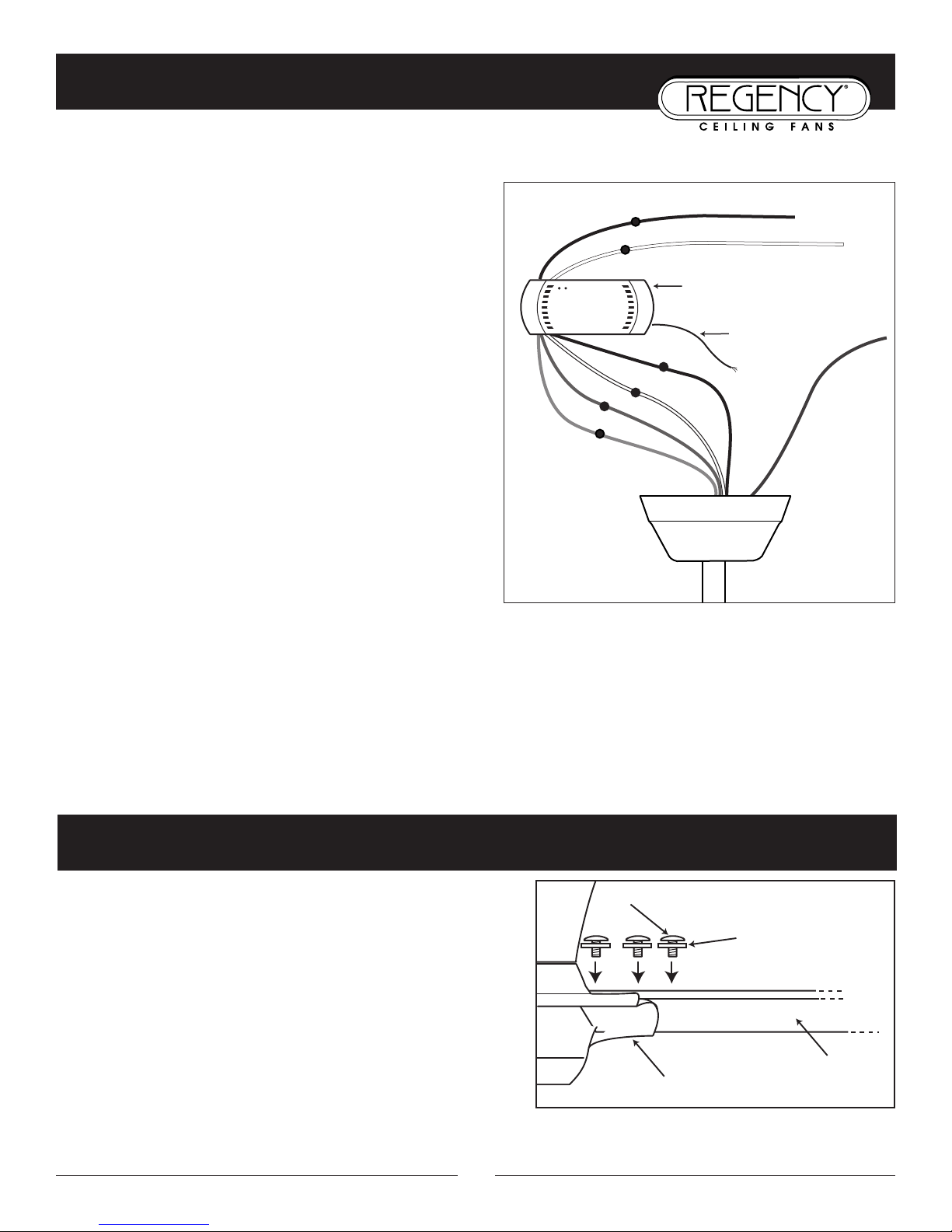
ELECTRICAL CONNECTIONS
Screw
Washer
Blade Arm
Blade
Receiver
Antenna
G
R
A
Y
G
R
A
Y
B
L
U
E
B
L
U
E
W
H
I
T
E
W
H
I
T
E
B
L
A
C
K
B
L
A
C
K
G
R
E
E
N
G
R
O
U
N
D
B
L
A
C
K
S
U
P
P
L
Y
1
1
0
v
(
B
LA
C
K
)
W
H
I
T
E
S
U
P
P
L
Y
C
O
M
M
O
N
(
W
H
I
T
E
)
Be sure electricity is turned off at the main power box before wiring.*
*
Four wires are connected to the fan (plus the ground wire).
Black - the “hot” power to run fan.
White - the “common” power to run fan and light,
also referred to as “AC neutral”.
Blue - the “hot” power for lower light.
Gray - the “hot” power for upper light.
Green - ground wire.
Six wires are connected to the remote control receiver. Four
will connect to the four wires coming out of the fan
(matching color to color) and the remaining black wire and
white wire will connect to the building 110v AC circuit.
BE SURE ELECTRICITY IS TURNED OFF AT THE
MAIN POWER BOX BEFORE WIRING.
Connect six power wir
es as shown [Fig. 1], using wir
e nuts
provided. Connect green ground wires to building ground
wire circuit. Extend antenna wire inside canopy, but do not
Fig. 1
attach to any other wire.
NOTE: If power to the fan’s electrical ceiling box is controlled by a wall switch, the wall switch must remain ON
for the radio remote control to operate. Turning the wall switch OFF will turn off all fan/light function and resets
the receiver back to default mode. The wall switch will need to be tur
ned back ON to allow use of remote control.
* Restore power by replacing fuse or resetting circuit breaker ONLY AFTER ALL INSTALLATION AND ELECTRICAL
WORK IS COMPLETED AND DOUBLE-CHECKED.
BLADE ATTACHMENT
1. Place washer on screw. Insert this assembly through the
blade and start the screw into the blade arm. Repeat this
ocedur
pr
e without tightening the scr
have been star
2. Tighten each screw, starting with center screw.
ted into the blade ar
ew until all 3 screws
m (Fig. 2).
Fig. 2
8
Page 11
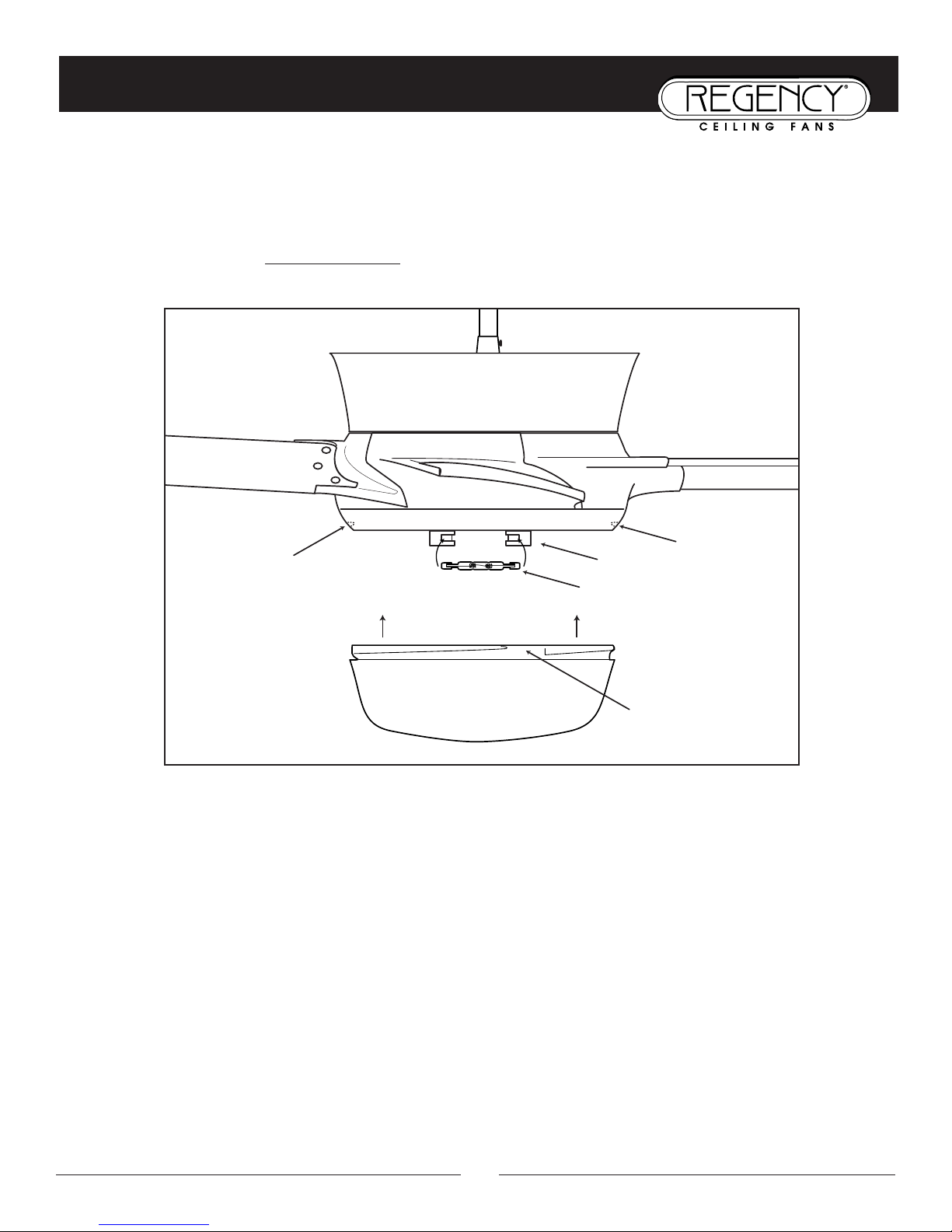
COMPLETING THE INSTALLATION
Glass shade
Lower socket
100W "J" type halogen bulb
Nub
Nub
Fan body
Indentation
1. Install “J” type halogen bulb into lower socket on bottom of fan. Do not touch bulb with bare fingers. Use tissue of bulb’s
packing to keep fingerprints and oils off bulb’s surface.
2. Lift bottom glass shade up to fan, aligning indentations in glass with nubs on bottom of fan [Fig. 2]. Turn glass
shade to secure in place. Do not over
tighten or glass may break..
CONGRATULATIONS! Your fan is now ready to enjoy!
9
Page 12
OPERATION
O
O
PPEERRAATTIINNGGBBUUTTTTOONNSSOONNTTHHE
HHII –– ffaann hhiigghh ssppeeeed
MMEEDD –– ffaann mmeeddiiuumm ssppeeeed
LLOOWW –– ffaann llooww ssppeeeed
OOFFFF –– ffaann ssppeeeedd oofff
UU//LL –– lliigghhtt bbrriigghhttnneessss aanndd ooffff ffuunnccttiioonn ffoorr uupplliigghht
DD//LL –– lliigghhtt bbrriigghhttnneessss aanndd ooffff ffuunnccttiioonn ffoorr lloowweerr lliigghht
RREEVV –– rreevveerrssee ((ddoowwnn oorr uupp)) aaiirr fflloow
• The light functions are controlled by pressing the light buttons. Hold a button down to increase or decrease light brightap button quickly to turn light off or on. The U/L button controls the up-light and the D/L button controls the lower
ness. T
light. They can be controlled independently and each has its own memory circuit that will keep the preset brightness you
have chosen. Just release the button at the desired light brightness and that setting will be remembered the next time the
light is tur
brightness is reached.
• Keep pressing the button for more than one second to dim the light and vary it cyclically from dim to bright and back again.
• Range of the transmitter is approximately 25 ft.
ned on. The pre-set brightness can be changed by holding down the light button again until the new desired
d
d
f
T
E
T
RRAANNSSMMIITTTTEER
d
R
t
t
w
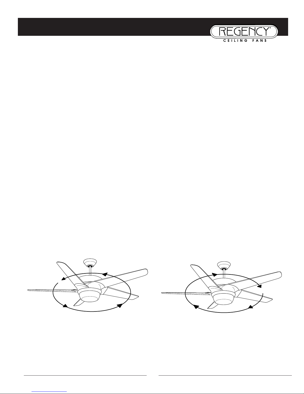
• Forward/Reverse Direction:
Forward
that can be felt below the fan. This is the normal direction for the fan to run when the weather is warm.
Reverse
during the cooler months.
is a counterclockwise rotation of the blades when viewed from beneath the fan. This will create a downward breeze
(clockwise) will draw air up through the blades and towards the ceiling, down the walls, and into the living space
WWAARRMM MMOONNTTHHS
FFoorrwwaarrdd ((ccoouunntteerrcclloocckkwwiissee)
S
)
CCOOOOLL MMOONNTTHHS
RReevveerrssee ((cclloocckkwwiissee)
S
)
10
Page 13

CARE AND CLEANING
P
eriodic cleaning of your new ceiling fan is about the only maintenance that is needed. Only use a soft brush or lint free cloth
to avoid scratching the finish. DO NOT use water when cleaning your ceiling fan. It could damage the motor or the blades
and/or create the possibility of electrical shock.
Periodically it may be necessary to re-tighten blade to blade arm screws or blade arm to motor screws to prevent clicking or
humming sound during operation. This is especially true in climates with broad temperature and humidity ranges and in fans
with painted or high gloss blades.
When dusting the blades, you must support the blade to prevent its bending - no pressure should be applied to the blades. If you
experience any flaws in the operation of your fan, please check the following points:
TROUBLESHOOTING - IN CASE OF DIFFICULTY
CCAAUUTTIIOONN:: SSwwiittcchh ooffff ppoowweerr ssuuppppllyy bbeeffoorree ccaarrrryyiinngg oouutt aannyy ooff tthheessee cchheecckkss.
IIff ffaann wwiillll nnoott ssttaarrtt::
• Check main and branch circuit breakers and/or fuses.
• Check line wire connections to fan and switch housing wiring.
• Make sure a fresh battery is in the remote control transmitter.
• Make sure the codes on both the transmitter and receiver are set the same.
• Fully extend the receiver antenna inside of canopy.
IIff ffaann iiss nnooiissyy:
• Check that all screws in motor housing are snug (but not overtight).
• Check that the screws securing blades to the motor are tight.
• Check that wire connectors in the canopy are not rattling against each other or the interior wall of the canopy.
••
Check that all glassware is finger tight and that bulb(s) are well held in the sockets.
Check that the canopy is firmly attached to hanging bracket and not vibrating against ceiling.
•
IIff ffaann wwoobbbblleess:
• Check that all blades ar
• Check to make sur
•
Wobble can also result from even the smallest deviations in distance from blade tip to blade tip - if measurements from
blade tip to blade tip are not equal, loosen screws connecting blade to bracket one at a time and adjust blade(s) so that
distances are equal. Interchanging adjacent blades may redistribute mass and result in smoother operation.
• Check to make sure that all hanger bracket screws and electrical box fasteners are tight. If electrical box is not tight to
the building, the whole fan, bracket, and electrical box may be moving as a result of the wobble. This can be dangerous if the electrical box should work loose from the building.
:
:
e that all glasswar
e fir
mly scr
ewed into blade ar
e and shades are fastened properly.
ms.
.
egencyfan.com
isit www
V
.r
11
Page 14

Page 15

Page 16

THANK YOU FOR PURCHASING A REGENCY CEILING FAN.
Write to us at:
Regency Ceiling Fans
P.O. Box 730
Fenton, MO 63026
Visit us on the Web at: www.regencyfan.com
5/03 Regency Ceiling Fans
 Loading...