

Page 1
Gas Stoves
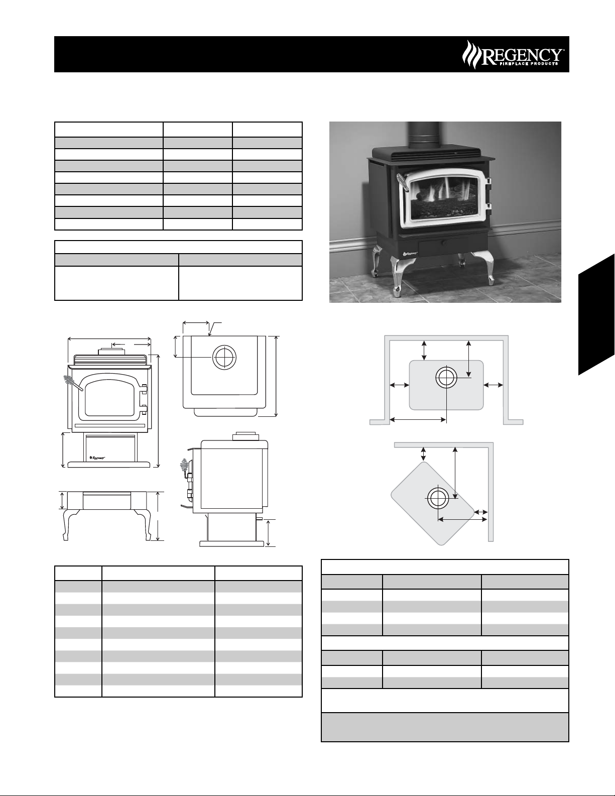
C34 Freestanding Direct Vent Gas Stove
Model C34-NG3 C34-LP3
Fuel Type Natural Gas Propane
Minimum Supply Pressure 5.0” W.C. (1.25 kPa) 12.0” W.C. (3.00 kPa)
Manifold Pressure - High 3.82” W.C. (0.95 kPa) 11” W.C. (2.74 kPa)
Manifold Pressure - Low 1.1” W.C. (0.27 kPa) 2.9” W.C. (0.72 kPa)
Orifi ce Size #36 #52
Minimum Input 16,000 BTU/h 16,000 BTU/h
Maximum Input 32,000 BTU/h 32,000 BTU/h
Vent Sizing 4” Inner / 6-5/8” Outer 4” Inner / 6-5/8” Outer
Approved Venting Systems
Flex Vent Systems: FPI AstroCap™ Flex Vent
Rigid Pipe Vent Systems: Simpson Dura-Vent® Direct Vent GS
A
G
American Metal Products Ameri Vent
Security Secure Vent®
Selkirk Direct-Temp.
J
Gas Line In
H
Back wall
L
C34 Gas Stove
Gas Stoves
N
Side wall
B
D
F
E
Gas Line In
Dimension Description C34
A Unit Width 24” (610mm)
B Unit Height 29-11/16” (737mm)
C Unit Depth 21-5/8” (549mm)
D Pedestal Height 11-3/4” (298mm)
E Cast Leg Height
F Bottom shield Height 4” (102mm)
G Vent centerline to Side 12” (305mm)
H Vent centerline to Back 7” (178mm)
I Gas Line Height (from base) 9” (229mm)
J Side to Gas Line 4-1/2” (114mm)
(including Bottom shield) 11-3/4” (298mm)
C
K K
Side wall
M
Wall
O
P
I
Alcove clearances
Dimension Description C34
K Side Wall to Unit 10” (250mm)
L Back Wall to Unit 6” (150mm)
M Side wall to Vent Centerline 22” (559mm)
N Back wall to Vent Centerline 13” (330mm)
Corner Clearances
Dimension Description C34
O Wall to Unit Corner 1.5” (38mm)
P Wall to vent centerline 14” (356mm)
Minimum ceiling height is 36" (914mm) from top of unit.
Minimum clearance to vent is 1-1/4” (32mm).
The above listed clearances are minimum distances to combustible
materials. When installing on carpet or vinyl fl ooring the bottom pedestal
cover plate must be installed.
Wall
O
P
145June 2007 Regency Product Specifi cations Book
Page 2
C34 Gas Stove
Regency Direct Vent System
Horizontal Terminations Only
These venting systems, in combination with the C34 Direct Vent Gas
Fireplace, have been tested and listed as a direct vent heater system
by Warnock Hersey. The location of the termination cap must conform
to the requirements in the Vent Terminal Locations diagram.
FPI Direct Vent (Flex) System Termination Kits include all the parts
needed to install the C34 using a fl exible vent.
FPI Kit # Length Contains:
#946-116 2 Feet 1) 6-5/8” Rigid Pipe Section (Kit length)
#946-216 4 Feet
Gas Stoves
Notes:
1) Liner sections should be continuous without any joints or seams.
2) Only Flex pipe purchased from Regency may be used for Flex
installations.
3) Horizontal sections must be supported every 3 feet.
2) 4” fl exible liner (Kit length)
3) spring spacers (4)
4) 90° Elbow
5) Adjustable pipe section 13-1/2” to 24”
6) thimble cover (1)
7) thimble (1)
8) adapter
9) AstroCap termination cap (1)
10) trim collar (2)
11) tube of Mill Pac (1)
12) S.S. screws #8 x 1-1/2”, self-tap, (12)
13) Blk. screws #8 x 1-1/2”, self-tap, (14)
14) Blk. screws #8 x 1-1/2” drill point, (4)
15) S.S. screws #8 x 1-1/2” drill point, (4)
16) Wood screws #8 x 1” (8)
17) vinyl siding standoff
(optional #946-206)
Wall Thimble
(only required
in Canada)
Gas Stoves
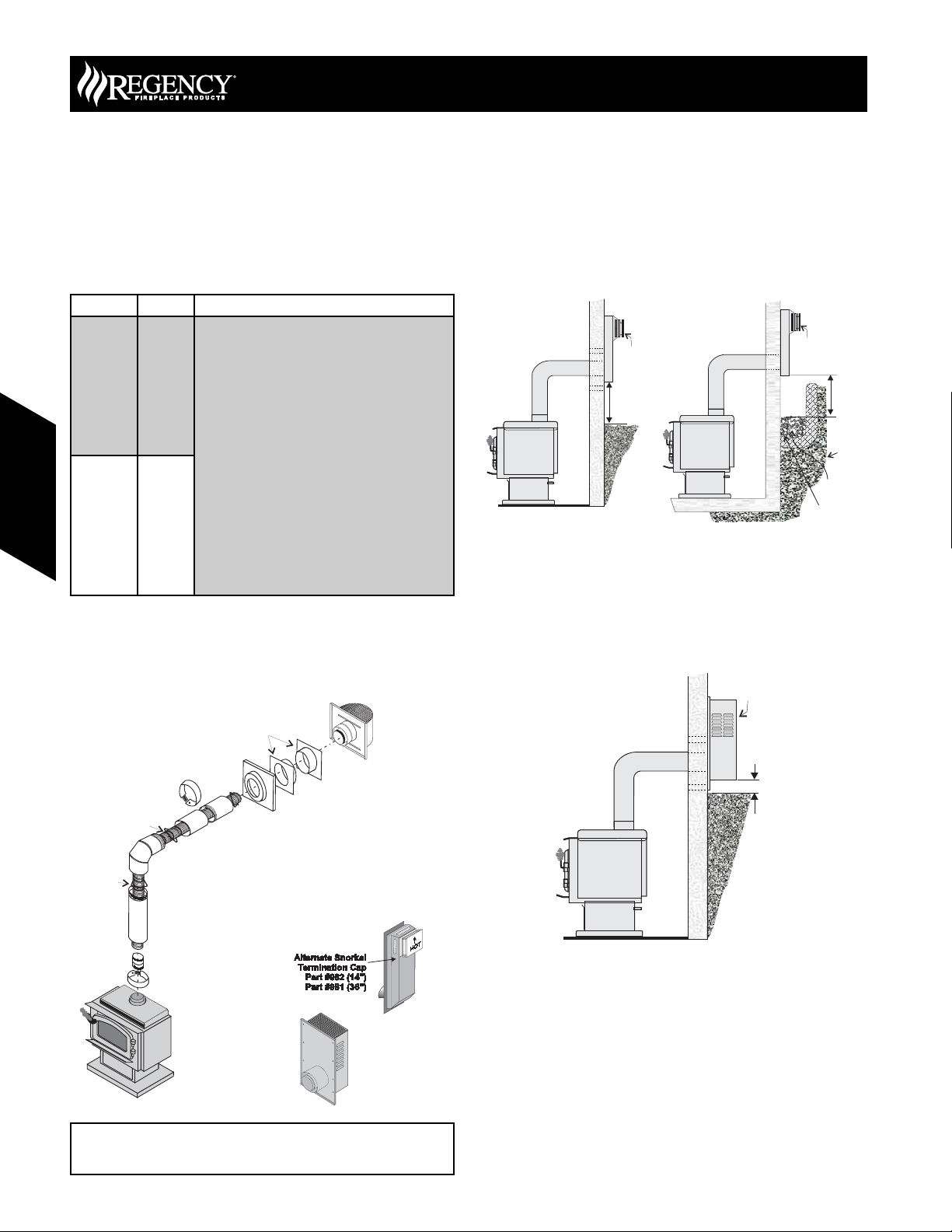
Snorkel Terminations
Snorkel Terminations:
For installations requiring a vertical rise on the exterior of the building,
14-inch and 36-inch tall Snorkel Terminations and the Riser Vent are
available. Follow the same installation procedures as used for standard
Horizontal Termination. NEVER install the snorkel upside down.
Dura-Vent
Snorkel
Min. 12"*
(305mm)
Below Grade Snorkel Installation (Dura-Vent Only)
If the Snorkel Termination must be installed below grade, i.e. basement
application, proper drainage must be provided to prevent water from
entering the Snorkel Termination. Refer to Rigid Pipe Installation
instructions for details. Do not attempt to enclose the Snorkel within the
wall, or any other type of enclosure.
Riser Vent
Termination
Dura-Vent
Snorkel
Adequate
drainage
Gravel
Min. 12"*
Window
Well
(305mm)
Thimble
4" ID Liner
Spacer
Spring
Trim Collar
Trim
Collar
o
90 Elbow
Pipe Length
Adapter
Cover
Adjustable Pipe
Length 13-1/2" - 24",
2 pieces
Alternate Horizontal
Termination Caps
AstroCap
Termination Cap
(Part# 946-523/P)
Alternate:
Horizontal
Riser Vent
Terminal
Part# 640-530/P
Min. 6-1/4"*
(159mm)
If required by the external termination location the listed
alternate termination caps may be used. (Refer to Page 11)
146 June 2007 Regency Product Specifi cations Book
Page 3

a
P
Gas Stoves
Vent Restrictor Position
Vent restriction is required for certain venting installations, see the
diagrams in "Venting Arrangement" section to determine if they are
required for your installation.
The vent restrictor has three settings: "C" Center (factory setting), "L"
Left, and "R" Right. Simply loosen the screws and push the vent restrictor
plate to the correct position. Tighten the screws.
Rigid Pipe Venting Systems
Horizontal or Vertical Terminations
Vertical
Termination
Cap
Storm Collar
Vinyl Siding
Flashing
Ceiling Firestop
Pipe Length
o
90 Elbow
24" Pipe
Length
Standoff (Optional)
Adj.Pipe Length
11" - 14-5/8"
Wall Thimble
C34 Gas Stove
Horizontal
Termination C
# 946-523/
Gas Stoves
If required by the external termination location the listed
alternate termination caps may be used. (Refer to Page 11)
147June 2007 Regency Product Specifi cations Book
Page 4

C34 Gas Stove
Venting Arrangements - Vertical
Terminations
Rigid Pipe System
(Propane & Natural Gas)
The C34 is approved for a maximum 30 ft. straight vertical, with Rigid
Pipe vent systems for Propane and Natural Gas.
The shaded area in the diagram (right) shows allowable venting
confi gurations with a maximum of two 45° elbows allowed. Terminations
falling in the shaded area must have the Vent Restrictor Position set to
“R” Right. (refer to Page 113)
• Vent must be supported at offsets.
• Horizontal sections must be supported every 3 feet
• Firestops are required at each floor level and whenever
passing through a wall.
• Maintain clearances to combustible materials.
• Minimum of 1’ pipe section between elbows.
Gas Stoves
Horizontal (Feet)
2
0
34
32
30
28
26
Max. 6’ (1.8m)
4
6
8
10
Vertical Venting with Two (2) 90° Elbows
Gas Stoves
Option V H V+ V1 Maximum total pipe length, of
A) 1’ Min. 4’ Max. 2’ Min.
B) 2’ Min. 5’ Max. 3’ Min.
C) 3’ Min. 6’ Max. 4’ Min.
D) 4’ Min. 7’ Max. 5’ Min.
E) 5’ Min. 8’ Max. 6’ Min.
Two 45° elbows = One 90° elbow
all sections, must not exceed
30 feet.
Total horizontal sections must
not exceed 8 feet.
Minimum of 1 foot between
90° elbows is required.
Vent Restrictor in position “C” (Center), refer to page 113.
24
22
20
Maximum: 30 ft. (9.1m)
18
Vertical Height (Feet)
16
Maximum: 24 ft. (7.3m)
14
12
10
8
6
4
2
0
Minimum 10’6” (3.2m)
148 June 2007 Regency Product Specifi cations Book
Page 5

6
8
10
12
10
12
Gas Stoves
Venting Arrangements - Horizontal
Terminations
This diagram shows all allowable combinations of vertical runs with
horizontal terminations, using one 90° elbow (two 45º
one 90° elbow).
The lightly shaded area,
, in the diagram shows allowable
combinations with Vent Restrictor in position “C” (Center), refer to
page 113.
The darker shaded area,
, in the diagram shows allowable
combinations with Vent Restrictor in position “L” (Left), refer to page
113 .
• Maintain clearances to combustibles.
• Horizontal vent must be supported every 3 feet.
• Firestops are required at each floor level and whenever
passing through a wall.
elbows equal
C34 Gas Stove
Horizontal Venting with Two (2) 90°
Elbows
Two 45° elbows = One 90° elbow
Option V H + H1 Maximum total pipe length, of all
A) 4’ Min. 6’ Max.
B) 5’ Min. 7’ Max.
C) 6’ Min. 8’ Max.
Vent Restrictor in position “C” (Center), refer to page 113.
sections, must not exceed 30 feet.
Total horizontal sections must not
exceed 8 feet.
Minimum of 1 foot between 90°
elbows is required.
A vent guard may be required as per local codes, refer to page 11 for
“Exterior Vent Termination Locations”.
Gas Stoves
Note: FPI Direct Vent System (Flex) is only approved for horizontal
terminations.
Horizontal (Feet)
2
0
24
22
20
18
Max. 5 ft. (1.5m)
4
8
6
12
10
14
Vertical Height (Feet)
16
14
12
Vent Restrictor on posittion “L”
10
Maximum: 30 ft. (9.1m)
8
Vent Restrictor on posittion “C”
6
4
2
Minimum 6 ft.(1.8m)
Minimum 5 ft. (1.5m)
0
Maximum: 13 ft. (4m)
Maximum: 8’ 6” (2.6m)
149June 2007 Regency Product Specifi cations Book
 Loading...