

Page 1
WARNING:
If the information in these instructions are not followed exactly,
a fire or explosion may result causing property damage,
personal injury or loss of life.
FOR YOUR SAFETY
Do not store or use gasoline or other flammable vapors and
liquids in the vicinity of this or any other appliance.
Installation and service must be performed by a qualified
installer, service agency or the gas supplier.
FOR YOUR SAFETY
What to do if you smell gas:
Do not try to light any appliance
Do not touch any electrical switch:
do not use any phone in your
building.
Immediately call your gas supplier
from a neighbour's phone. Follow
the gas supplier's instructions.
If you cannot reach your gas
supplier, call the fire department.
www.regency-fire.com
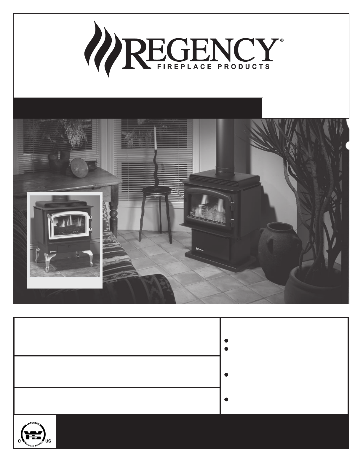
C33 Classic Freestanding Gas Stove
Owners &
Installation Manual
Classic C33 model shown above features
optional gold plated door and gold legs.
MODELS: C33-NG2 Natural Gas C33-LP2 Propane
Tested by:
Homeowner: Please keep these instructions for future reference.
908-636a
FPI FIREPLACE PRODUCTS INTERNATIONAL LTD. 6988 Venture St., Delta, BC Canada, V4G 1H4
Installer: Please complete the details on the back cover
and leave this manual with the homeowner.
01/31/05
Page 2
To the New Owner:
Congratulations! You are the owner of a state-of-the-art Gas Stove by Fireplace Products International
Ltd. The Regency Gas Series of hand crafted appliances has been designed to provide you with all the
warmth and charm of a woodstove, at the flick of a switch. The models C33-NG2 and C33-LP2 have
been approved by Warnock Hersey for both safety and efficiency. As it also bears our own mark, it
promises to provide you with economy, comfort and security for many trouble free years to follow.
Please take a moment now to acquaint yourself with these instructions and the many features of your
CLASSIC Freestanding Gas Stove.
2
Regency CLASSIC C33-2 Freestanding Gas Stove
Page 3

TABLE OF CONTENTS
Page
Safety Label
Safety Label............................................................. 4-5
Installation
Before you start .......................................................... 6
General Safety Information .......................................... 6
Installation Checklist ................................................... 7
Clearances to Combustibles ....................................... 7
Optional Fan Installation..............................................7
Pedestal Assembly..................................................... 8
Leg and Bottom Shield Assembly ............................... 9
Optional Outside Air.................................................... 9
-Outside air through pedestal bottom .................... 9
-Outside air through pedestal rear ......................... 9
Draft Hood................................................................... 9
Venting ....................................................................... 9
-Venting requirements........................................... 9
Gas Connection ........................................................ 10
System Data Table ................................................... 10
High Elevation ........................................................... 10
Gas Pipe Pressure Testing ....................................... 10
Test for Flue Spillage ................................................ 11
Log Set Installation ................................................... 11
Safety Latch.............................................................. 12
Door Handle .............................................................. 12
Optional Remote Wall Switch.................................... 12
Optional Remote Control Installation ......................... 12
Optional Wall Thermostat.......................................... 12
Wiring Diagram ......................................................... 13
Final Check............................................................... 12
Normal Operating Sounds of Gas Appliances............ 13
Page
Operating Instructions
Operating Instructions ............................................... 14
Lighting Procedure .................................................... 14
Shutdown Procedure ................................................. 14
Copy of Lighting Plate Instructions ............................ 15
Maintenance
Maintenance Instructions .......................................... 14
General Vent Maintenance........................................ 16
Thermopile/Thermocouple ......................................... 16
Aeration Adjustment.................................................. 16
Pilot Adjustment ....................................................... 16
Log Replacement ...................................................... 17
Gold Plated Doors..................................................... 17
Glass Replacement................................................... 17
Removing Valve Assembly ........................................ 18
Installing Valve Assembly ......................................... 18
Parts list
Replacement & Spare Parts List ............................... 19
Warranty
Warranty ................................................................... 23
Regency CLASSIC C33-2 Freestanding Gas Stove 3
Page 4
SAFETY LABEL
Listed: GAS FIRED VENTED ROOM HEATER
Certified for:
Report No.
CANADA and USA
476-1345-00 (Oct. 1996)
FPI Fireplace Products International Ltd.
Delta, BC, Canada
FACTORY EQUIPPED FOR NATURAL GAS:
Model C33-NG2
Minimum supply pressure 5" WC/C.E. (1.25Kpa)
Manifold pressure High 3.8" WC/C.E. (0.94Kpa)
Manifold pressure Low 1.1" WC/C.E. (0.27Kpa)
Orifice size 36 DMS
Altitude 0-2000 ft/pi (0-610 m)
Maximum Input 33,000 BTUH (9.67Kw/h)
Minimum Input 17,000 BTUH (4.98Kw/h)
Factory Equipped for 0-2000 ft.
Minimum supply pressure 5" WC/C.E. (1.25Kpa)
Manifold pressure High 3.8" WC/C.E. (0.94Kpa)
Manifold pressure Low 1.1" WC/C.E. (0.27Kpa)
Orifice size 38 DMS
Altitude 2000-4500 ft/pi (610-1370m)
Maximum Input 29,000 BTUH (8.5Kw/h)
Minimum Input 15,300 BTUH (4.48Kw/h)
Serial No.
201
HIGH ALTITUDE CONVERTED NATURAL GAS:
Model C33-NG2
Field Convertable for Altitude 2000-4500 ft.
(Report No.476-1345-00)
Made in Canada
908-634a
DO NOT REMOVE THIS LABEL
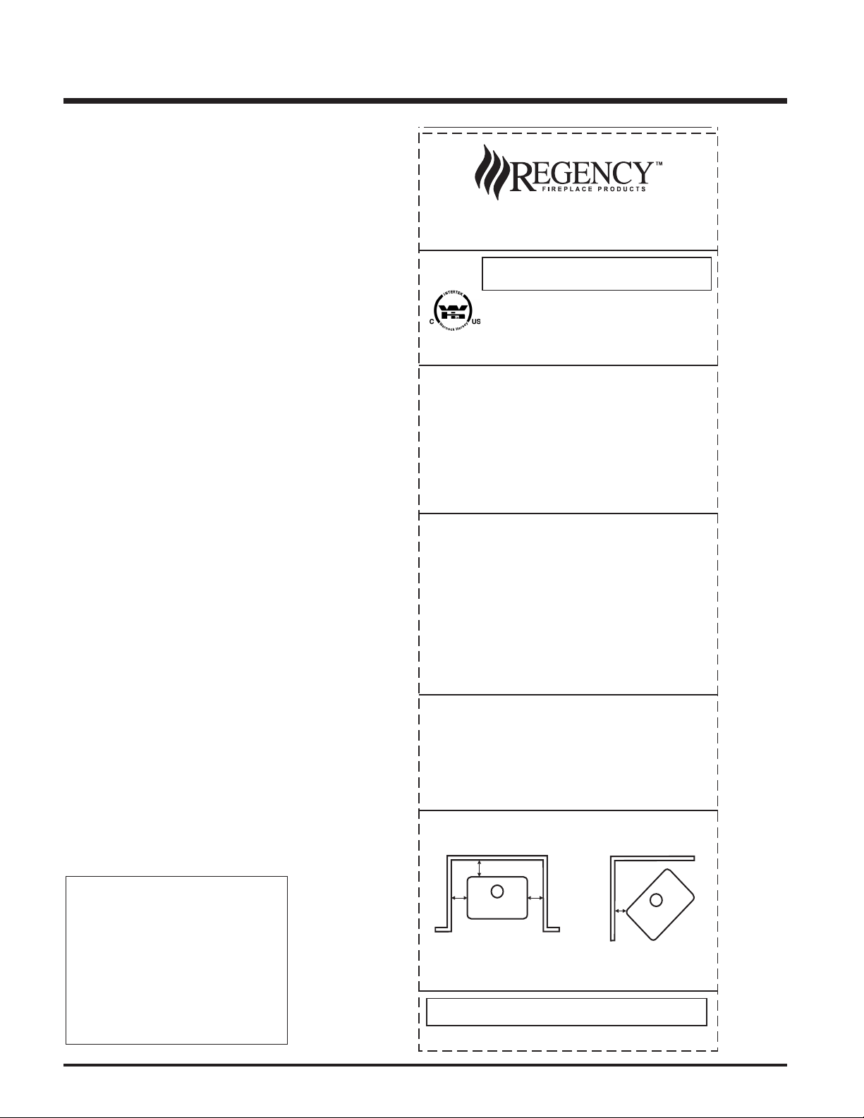
Minimum Clearances to Combustibles
Back wall
Side wall
E
A - 10"
E - 1.5"
Minimum ceiling height from top of unit: 36"/914mm
A
A
B
Back wall
Side wall
Side wall
GAS FIRED VENTED ROOM HEATER
This appliance must be installed in accordance
with local codes, if any; If not, follow:
ANSI Z223.1/CAN 1-B149.
Electrical Supply (115 V, 1.13 A, 60 Hz)
Not for use with solid fuel.
Optional Fan: (Part #490-917)
B-6"
Tested to: ANSI Z21.88b-2003/CSA 2.33b-2003,
CAN/CGA-2.17-M91
This is a copy of the label that accompanies
each CLASSIC Freestanding Gas Stove - Nat-
ural Gas. We have printed a copy of the
contents here for your review. The safety label
is located on the back panel.
NOTE: Regency units are constantly being
improved. Check the label on the unit and if there
is a difference, the label on the unit is the correct
one.
For the State of Massachusetts, installation
and repair must be done by a plumber or
gasfitter licensed in the Commonwealth of
Massachusetts.
For the State of Massachusetts, flexible
connectors shall not exceed 36 inches in
length.
For the State of Massachusetts, the appliances individual manual shut-off must be a
t-handle type valve.
4
Regency CLASSIC C33-2 Freestanding Gas Stove
Page 5
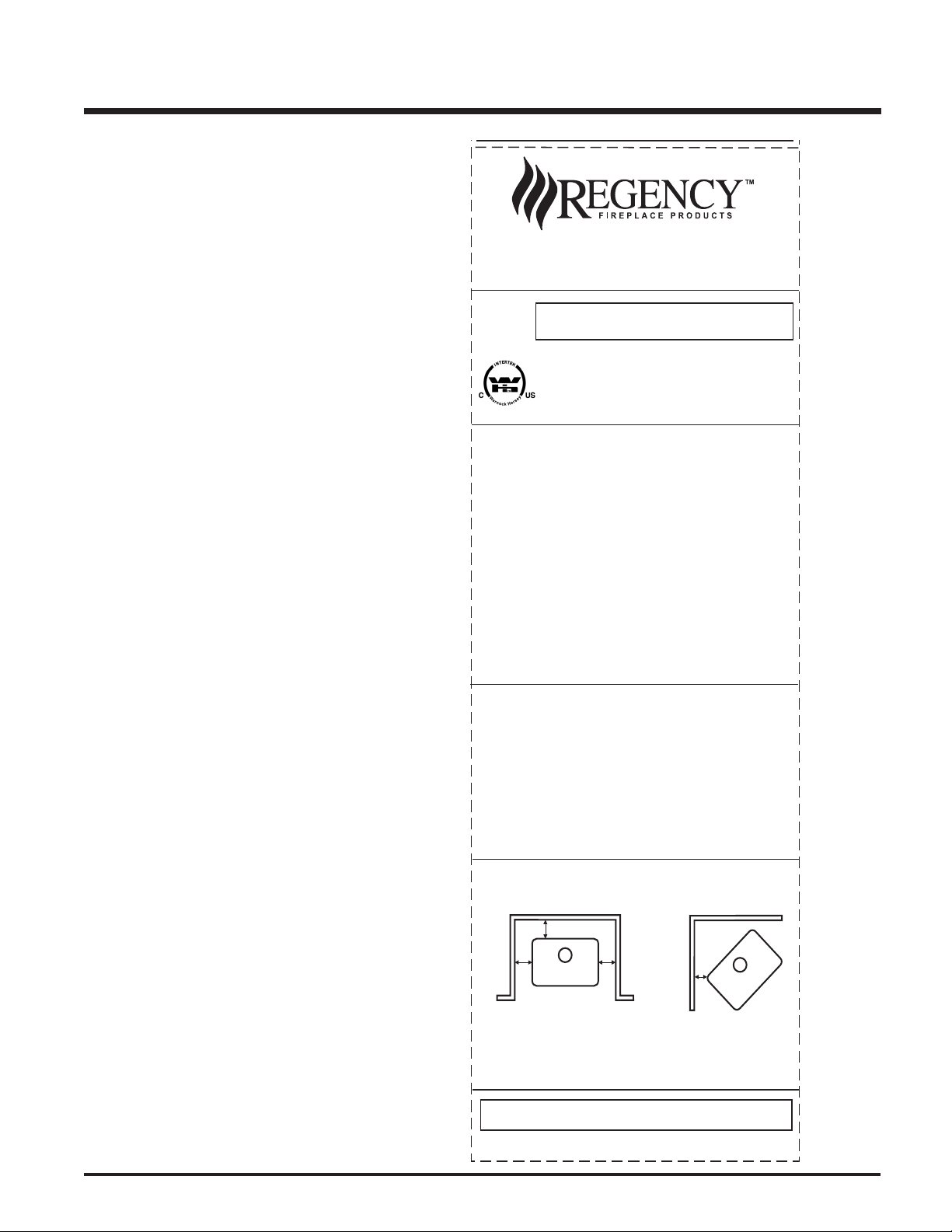
This is a copy of the label that accompanies each
Minimum supply pressure 12" WC/C.E.(2.85Kpa)
Manifold pressure High 11" WC/C.E.(2.61Kpa)
Manifold pressure Low 2.9" WC/C.E.(0.72Kpa)
Orifice size 52 DMS
Altitude 0-2000 ft/pi (0-610 m)
Maximum Input 33,000 BTUH (9.67Kw/h)
Minimum Input 17,000 BTUH (4.98Kw/h)
FACTORY EQUIPPED FOR PROPANE:
Model C33-LP2
GAS FIRED VENTED ROOM HEATER
This appliance must be installed in accordance
with local codes, if any; If not, follow:
ANSI Z223.1/CAN 1-B149.
Electrical Supply (115 V, 1.13 A, 60 Hz)
Not for use with solid fuel.
Optional Fan: (Part #490-917)
Listed
Certified for:
Report No.
Tested to:
: GAS FIRED VENTED ROOM HEATER
CANADA and USA
476-1345-00 (Oct. 1996)
ANSI Z21.88b-2003/CSA 2.33b-2003
FPI Fireplace Products International Ltd.
Delta, BC, Canada
Serial No.
200
Made in Canada
908-635a
DO NOT REMOVE THIS LABEL
Minimum Clearances to Combustibles
Minimum ceiling height from top of unit: 36"/914mm
Back wall
Side wall
E
A - 10"
E - 1.5"
A
A
B
Back wall
Side wall
Side wall
B-6"
CLASSIC Freestanding Gas Stove - Propane.
We have printed a copy of the contents here for
your review. The safety label is located on the
back panel.
NOTE: Regency units are constantly being improved. Check the label on the unit and if there
is a difference, the label on the unit is the correct
one.
SAFETY LABEL
Regency CLASSIC C33-2 Freestanding Gas Stove 5
Page 6
INSTALLATION
BEFORE YOU START
Safe installation and operation of this appliance
requires common sense, however, we are
required by the Canadian Safety Standards
and ANSI Standards to make you aware of the
following:
INSTALLATION AND REPAIR
SHOULD BE DONE BY A QUALIFIED SERVICE PERSON. THE APPLIANCE SHOULD BE INSPECTED
BEFORE USE AND AT LEAST ANNUALLY BY A PROFESSIONAL
SERVICE PERSON. MORE FREQUENT CLEANING MAY BE REQUIRED DUE TO EXCESSIVE LINT
FROM CARPETING, BEDDING MATERIAL, ETC. IT IS IMPERATIVE
THAT CONTROL COMPARTMENTS, BURNERS AND CIRCULATING AIR PASSAGEWAYS OF THE
APPLIANCE BE KEPT CLEAN.
DUE TO HIGH TEMPERATURES,
THE APPLIANCE SHOULD BE LOCATED OUT OF TRAFFIC AND
AWAY FROM FURNITURE AND DRAPERIES.
WARNING: FAILURE TO INSTALL
THIS APPLIANCE CORRECTLY
MAY CAUSE A SERIOUS HOUSE
FIRE AND WILL VOID YOUR WARRANTY.
CHILDREN AND ADULTS SHOULD
BE ALERTED TO THE HAZARDS OF
HIGH SURFACE TEMPERATURES,
ESPECIALLY THE FIREPLACE
GLASS, AND SHOULD STAY AWAY
TO AVOID BURNS OR CLOTHING
IGNITION.
YOUNG CHILDREN SHOULD BE
CAREFULLY SUPERVISED WHEN
THEY ARE IN THE SAME ROOM AS
THE APPLIANCE.
CLOTHING OR OTHER FLAMMABLE MATERIAL SHOULD NOT BE
PLACED ON OR NEAR THE APPLIANCE.
IMPORTANT:
SAVE THESE
INSTRUCTIONS
The CLASSIC Freestanding Gas Stove must be
installed in accordance with these instructions.
Carefully read all the instructions in this manual
first. Consult the "authority having jurisdiction"
to determine the need for a permit prior to
starting the installation.
GENERAL SAFETY
INFORMATION
1) The appliance installation must conform
with local codes or, in the absence of local
codes, with the current Canadian or National Gas Codes, CAN1-B149 or ANSI Z223.1
Installation Codes.
2) The appliance when installed, must be electrically grounded in accordance with local
codes, or in the absence of local codes with
the current National Electrical Code, ANSI/
NFPA 70 or CSA C22.1 Canadian Electrical
Code.
3) This appliance is Listed for bedroom installations when used with a Listed Millivolt
Thermostat. Some areas may have further
requirements, check local codes before
installation.
4) This appliance is Listed for Alcove installations, maintain minimum Alcove clearances
as follows, minimum ceiling height of 65-11/
16", minimum width of 48" and a maximum
depth of 36".
5) This unit is not approved for installation into
a mobile home.
6) See general construction and assembly
instructions.
7) This appliance must be connected to a vent
and terminate to the outside of the building
envelope. Never vent to another room or
inside a building.
8) Inspect the venting system annually for
blockage and any signs of deterioration.
9) Any safety glass removed for servicing
must be replaced prior to operating the
appliance.
10)To prevent injury, do not allow anyone who
is unfamiliar with the operation to use the
fireplace.
11)Wear gloves and safety glasses for protection while doing required maintenance.
12)Under no circumstances should this appliance be modified. Parts that have to be
removed for servicing should be replaced
prior to operating this appliance.
13)Installation and any repairs to this appliance should be done by a qualified service
person. A professional service person
should be called to inspect this appliance
annually. Make it a practice to have all of
your gas appliances checked annually.
14)Do not strike the glass door.
15)Under no circumstances should any solid
fuels (wood, paper, cardboard, coal, etc.)
be used in this appliance.
16)The appliance area must be kept clear and
free of combustible materials, (gases and
other flammable vapours and liquids).
Emissions from burning wood or gas could
contain chemicals known to the State of
California to cause cancer, birth defects or
other reproductive harm.
INSTALLATION
CHECKLIST
1) Locate appliance, see Clearances to Com-
bustibles, page 7.
2) Install Optional Fan, page 7.
3) Assemble stove base - pedestal or legs,
pages 8 and 9.
4) If outside air is being used, see page 9.
5) Install venting, page 9.
6) Make gas and electrical connections, page
10. Test the pilot. Must be as per diagram,
pages 16.
7) Test gas pressure, page 10.
8) Test for flue spillage, page 11.
9) Install log set, see page 11.
10)Install optional Wall Switch, Remote Con-
trol, or Wall Thermostat, page 12.
11)Final check, page 12.
Before leaving this unit with the customer, the
installer must ensure that the appliance is firing
correctly and operation fully explained to customer.
This includes:
1) Clocking the appliance to ensure the cor-
rect firing rate (rate noted on label) after
burning appliance for 15 minutes.
6
Regency CLASSIC C33-2 Freestanding Gas Stove
Page 7
INSTALLATION
2) If required, adjusting the primary air to
ensure that the flame does not carbon. First
allow the unit to burn for 15-20 min. to
stabilize.
3) Check for proper draft.
CAUTION: Any alteration to the product that causes sooting or carboning that results in damage is not the
responsibility of the manufacturer.
CLEARANCES TO
COMBUSTIBLES
The clearances listed below are MINIMUM distances. Measure the clearance to both the
appliance and the chimney connector. The
farthest distance is correct if the two clearances do not coincide. For example, if the appliance
is set as indicated in one of the diagrams but the
back wall is too close, move the stove until the
correct clearance to the back wall is obtained.
This unit can be installed on a solid combustible
surface like a wood floor. This unit can also be
installed directly on carpeting or vinyl when the
bottom pedestal cover plate (provided with the
unit) is installed.
This appliance may be installed only with the
clearances as shown in the situations pictured. Do not combine clearances from one
type of installation with another in order to
achieve closer clearances. Use the minimum
clearances shown in the diagrams. Alcove
installations are approved, as long as side wall
clearances are maintained.
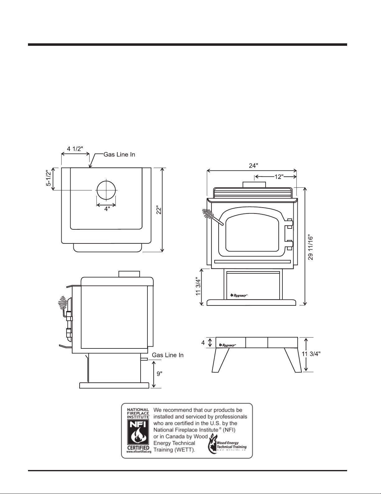
C33-2 Clearances to Combustibles
A Side Wall to Unit 10" / 250 mm
B Back Wall to Unit 6" / 150 mm
E Side Wall to Unit 1.5" / 38 mm
C33-2 Reference Dimensions
to Flue Centerline
C Back Wall 11-1/2"/ 292 mm
D Side Wall 22" / 559 mm
F Side Wall 13" / 330 mm
Minimum ceiling height is 36" / 914 mm
from top of unit.
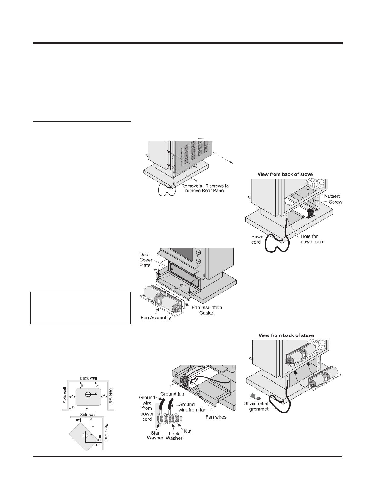
OPTIONAL FAN
INSTALLATION
Important: Disconnect the power
supply before installation or servicing.
For pedestal unit: To install the fan in an
installed stove-access from front through
the pedestal by following the directions
below. If the stove is not installed - access
through rear and follow steps 4 to 17.
For leg unit: remove 7 screws, remove
bottom access panel and install fan assembly and follow steps 4 to 17.
1) Open pedestal door and remove door cover plate by removing 4 screws. See diagram 1.
Diagram 1
2) Remove valve cover plate by removing 2
screws.
3) Remove wire from piezo ignitor.
4) Screw the four 8-32 x 3/4 screws provided
into the nutserts as shown in diagram 3. Do
not tighten screws.
5) Push all the fan wires through the hole on
the fan assembly. See diagram 2
.
6) Put power cord (shown in diagram 3)
through the hole and pull through to front of
unit for easier installation of ground wire.
7) Place fan assembly partially in door cover
plate hole. See diagram 2.
8) Attach the 2 ground wires (green) to the
ground lug as per diagram 2.
Note: Ground lug is located on the bottom
of the fan assembly. See diagram 2.
Diagram 3
9) Lift the fan assembly in through the pedestal and up through the cut out as shown in
diagrams 3 and 4.
10)Put the insulation gasket on the back of the
fan. Line up the keyhole slots with the
matching screws and pull back slightly to
lock into place. While holding fan assembly
in place, tighten screws.
Diagram 4
Diagram 2
Regency CLASSIC C33-2 Freestanding Gas Stove 7
Page 8
INSTALLATION
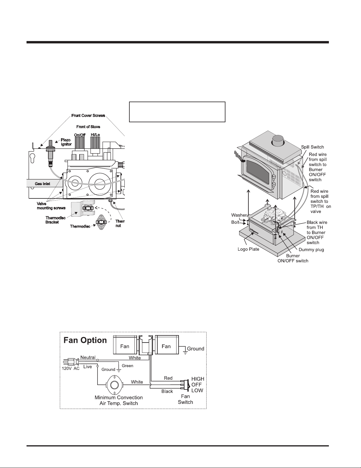
Wiring
11)Remove the dummy plug from the right side
of the bottom shield or pedestal and install
the supplied fan switch.
12)Attach hot wire from power cord to the
thermodisc.
13)Slide the thermodisc under the bracket.
View from Bottom of Stove
14)Connecting wires to the 3 way switch -
a. Connect the red wire from the fan to the
top of the 3 way switch.
b. Connect black wire from fan to the bottom
of the 3 way switch.
c. Connect white jumper wire to middle of
the three way switch. See wiring diagram
below.
15)Connect white wire from fan motor to neutral on the power cord.
16)Pull power wire back and put strain relief
grommet in place as per diagram 4.
17)Reverse steps 3-1 to complete installation.
Note: The #8 ground lug is a dedicated
ground for mobile home use only.
Only C34 unit is approved for mobile homes.
Caution: Ensure that wires do
NOT touch hot surfaces.
Fan Removal
1) Disconnect the power to fan.
2) Allow the stove to cool to room tempera-
ture.
3) Open the pedestal door and remove the
screws on the door cover plate. Leg Units:
Remove bottom access panel.
4) Loosen the nutsert screws.
5) Remove Fan Assembly from the key slots
at the fan base. Take the fan out from the
rectangular opening . Diagram 3.
6) Turn the fan around 90 degrees (Pedestal
units only). Diagram 2.
7) Disconnect the green ground wires to the
grounding lug.
8) Disconnect the white wire of the fan from
the power cord.
9) Disconnect red wire and black wire (from
fan to Fan Switch).
10)Take fan out from the stove body. Diagram
1.
PEDESTAL ASSEMBLY
1) For easier assembly, tip the stove on its
back (preferably onto a soft surface to
prevent scratching).
2) Unscrew the 4 bolts in the underside of the
stove. Align the holes in the corners of the
pedestal top with the corresponding holes
in the base of the stove. Use washers
which are supplied with the pedestal as
shown in diagram. Reinstall bolts.
Diagram 1
3) Hook up wires to Burner ON/OFF switch
and valve assembly (be careful not to pinch
wires). See Diagram 1.
4) Push the Regency logo into the two holes
in the front bottom left corner of the pedestal
cover plate.
Note: Any paint touch up should be done
prior to placing logo on pedestal.
Wiring Diagram
8
Regency CLASSIC C33-2 Freestanding Gas Stove
Page 9

INSTALLATION
LEG AND
BOTTOM SHIELD
ASSEMBLY
These instructions apply to the steel leg, painted cast leg and the gold plated cast leg. It will
be easier to attach the legs to the stove if it is
tipped on its back (preferably on a soft surface
to prevent scratching).
1) Remove the 4 bolts in the underside of the
base and discard.
2) Put the bottom shield up against the bottom
of the stove and loosely install the four
supplied bolts and washers into the threaded holes in the four corners of the bottom
the unit. Once the bolts are started, slip the
leg under the washer and tighten the bolts.
3) Hook up wires to Burner ON/OFF switch
and valve assembly as per pedestal assembly diagram (diagram 1).
4) Level the stove by adjusting the levelling
bolts in the bottom of each leg.
OPTIONAL
OUTSIDE AIR
If needed, outside air for combustion can be
brought in either through the bottom of the
pedestal or through the rear plate of the pedestal.
The pedestal cover plate must be installed when
using outside combustion air. Loosen the 4
screws on the rear of the pedestal and slide the
cover plate over them. Slide the plate to the left
to center it and tighten down the 4 screws.
Outside Air Through
Pedestal Bottom
Once you have properly marked the position of
your unit as outlined in "General Information"
and "Clearances to Combustibles", cut a minimum 3 inch diameter hole though the floor
directly under your pedestal base to the outside.
Pipe fresh air into the pedestal area by using a
minimum 3" duct pipe with a mesh grill at the
outside termination.
Note: Blanking plate combustion air hole
is 4" diameter.
IMPORTANT
Read all instructions carefully before starting
the installation. Failure to follow these instructions may create a fire or other safety hazard,
and will void the warranty. Be sure to check the
venting and clearance to combustible requirements. Consult your local building codes
before beginning installation.
DRAFT HOOD
The heater has a draft hood built into its back.
It must not be altered or obstructed, and the unit
must be installed so that the draft hood is in the
same atmospheric pressure zone as the combustion air inlet to the burner.
VENTING
This heater is a vented appliance and must be
connected to a chimney/flue in accordance
with installation codes.
Note: The rear cover plate is only at-
tached when outside air is being
used. Do not install it when using
room air for combustion.
Rear View
Outside Air Through
Pedestal Rear
Remove the blanking plate from the rear of the
pedestal cover plate and bend the two tabs out
90 degrees. Pipe fresh air into the pedestal area
by using a minimum 3" duct pipe with a mesh grill
at the outside termination. Attach the pipe to the
tabs with screws.
Note: The hole in the rear pedestal cov-
er plate is 4" diameter.
For your safety this heater is equipped with a
vent safety switch. This thermally actuated
switch is located within the draft hood and will
detect either a blocked chimney or backdraft
condition where the chimney flow has reversed and will react by shutting off the gas
supply.
Note: The spill switch is manually reset-
table and comes from the factory
in the open position. Before trying
to start up the unit, make sure the
red button on the spill switch is
pushed in.
Venting Requirements
Four inch diameter vent is required. B-Vent,
Class A or Masonry with a liner are all acceptable. Follow all venting manufacturer’s requirements and local building codes. For altitudes
above 2000 ft. we recommend that a minimum
flue height of 12 ft. is used.
Note: Proper sizing of gas vents is crit-
ical to proper operation of all gas
stoves and fireplaces. Ensure that
proper sizing tables or vent manufacturers instructions are followed.
Side View
Regency CLASSIC C33-2 Freestanding Gas Stove 9
Page 10

INSTALLATION
Installing into Existing
Woodstove Flue System
1) Clean existing chimney system.
2) Install stove pipe adapter
3) Install any reducers that may be needed to
fit 6" flue pipe adapter.
4) Run 4" flex liner into existing chimney.
5) Slip liner through 6" flue pipe and hook up
to flue collar with screws.
Note: For ease of instal-
lation, use a slip
section when installing
with a vertical flue
pipe.
GAS CONNECTION
The gas connection is a 3/8" NPT rigid pipe. The
gas line can be rigid pipe or to make installation
easier, use a listed flexible connector and/or
copper pipe if allowed by local codes. For
minimum and maximum supply pressure see
the System Data table below.
Note: During any pressure testing of
the gas supply piping system that
exceeds test pressures of 1/2
psig, this appliance and its individual shut-off valve must be disconnected from the piping system. If test pressures equal to or
less than 1/2 psig are used then
this appliance must be isolated
from the piping system by closing its individual manual shut-off
valve during the testing.
Output capacity:
The efficiency rating of the appliance is a
product thermal efficiency rating determined
under continuous operating conditions and
was determined independently of any installed
system.
SYSTEM DATA
(For 0 to 2,000 feet altitude)
Orifice Sizes:
Burner Natural Gas #36
Burner Propane #52
Max. Input Rating
Natural Gas 33,000 Btu/h
Propane 33,000 Btu/h
Min. Input Rating
Natural Gas 17,000 Btu/h
Propane 17,000 Btu/h
Output Capacity with blower Off
Natural Gas 23,200 Btu/h
Propane 23,100 Btu/h
Output Capacity with blower On
Natural Gas 24,600 Btu/h
Propane 24,420 Btu/h
Supply Pressure
Natural Gas min. 5.0" w.c
max. 8.0" w.c.
Propane min. 12.0" w.c.
max. 13.0" w.c.
Manifold Pressure High
Natural Gas 3.8" +/- 0.2" w.c.
Propane 11" +/- 0.2" w.c.
Manifold Pressure Low
Natural Gas 1.1" +/- 0.2" w.c.
Propane 2.9" +/- 0.2" w.c.
Electrical: 120V, 1.13A, 60 Hz.
Circulation Fan: (optional) 2 speed
75/125 CFM.
Log Set: Ceramic fiber, 4 per set.
HIGH ELEVATION
This unit is approved in Canada for altitude 0 to
4500 ft. (CAN1 2.17-M90) with the orifice supplied.
SYSTEM DATA
(For 2,000 to 4,500 feet altitude)
Orifice Sizes:
Burner Natural Gas #38
Max. Input Rating
Natural Gas 29,000 Btu/h
Min. Input Rating
Natural Gas 15,300 Btu/h
Output Capacity with blower Off
Natural Gas 20,400 Btu/h
Output Capacity with blower On
Natural Gas 21,600 Btu/h
GAS PIPE
PRESSURE TESTING
The appliance must be isolated from the gas
supply piping system by closing its individual
manual shut-off valve during any pressure
testing of the gas supply piping system at test
pressures equal to or less than 1/2 psig. (3.45
kPa). Disconnect piping from valve at pressures over 1/2 psig (14" w.c.).
The manifold pressure is controlled by a regulator built into the gas control, and should be
checked at the pressure test point.
Note: To properly check gas pressure,
both inlet and manifold pressures
should be checked using the valve
pressure ports on the valve.
1) Make sure the valve is in the "OFF" position.
2) Loosen the "IN" and/or "OUT" pressure
tap(s), turning counterclockwise with a
1/8" wide flat screwdriver.
3) Attach manometer to "IN" and/or "OUT"
pressure tap(s) using a 5/16" ID hose.
4) Light the pilot and turn the valve to "ON"
position.
5) The pressure check should be carried out
with the unit burning and the setting should
be within the limits specified on the safety
label.
6) When finished reading manometer, turn off
the gas valve, disconnect the hose and
tighten the screw (clockwise) with a 1/8"
flat screwdriver. Screw should be snug,
but do not over tighten.
10
Regency CLASSIC C33-2 Freestanding Gas Stove
Page 11

INSTALLATION
Valve Description
1) Gas cock knob
2) Manual high/low adjustment
3) Pilot Adjustment
4) Thermocouple Connection
5) Main Operator
6) Outlet Pressure Tap
7) Inlet Pressure Tap
8) Pilot Outlet
9) Main Gas Outlet
10)Flange Securing Screw Holes
11)Alternative TC Connection Point
12)Thermoelectric Unit
13)Additional Valve Mounting Hole
1) Start all exhaust fans in the home and then
close all doors and windows in the room.
2) Light the unit and set controls to maximum.
3) After five minutes, test that there is a “pull”
on the flue by placing a smoke match,
cigarette or similar device which gives off
smoke, on the edge of the draft hood. See
Diagram below.
The smoke should be drawn into the draft hood.
If the smoke is still not drawn into the draft hood,
turn the unit off and check for the cause of the
lack of draft. If necessary, seek expert advice.
Note: If the flue is blocked or has a strong
reverse flow, the thermally actuated safety switch mounted in the
draft hood will automatically shut
off the gas supply in less than 10
minutes. If the heater turns off
because of this during the spillage
test, check for the cause of the lack
of draft and if necessary, seek
expert advice.
To reset the thermally actuated safety switch,
let the unit cool for 10 minutes, then press the
red reset button on the back of the switch. See
Diagram below.
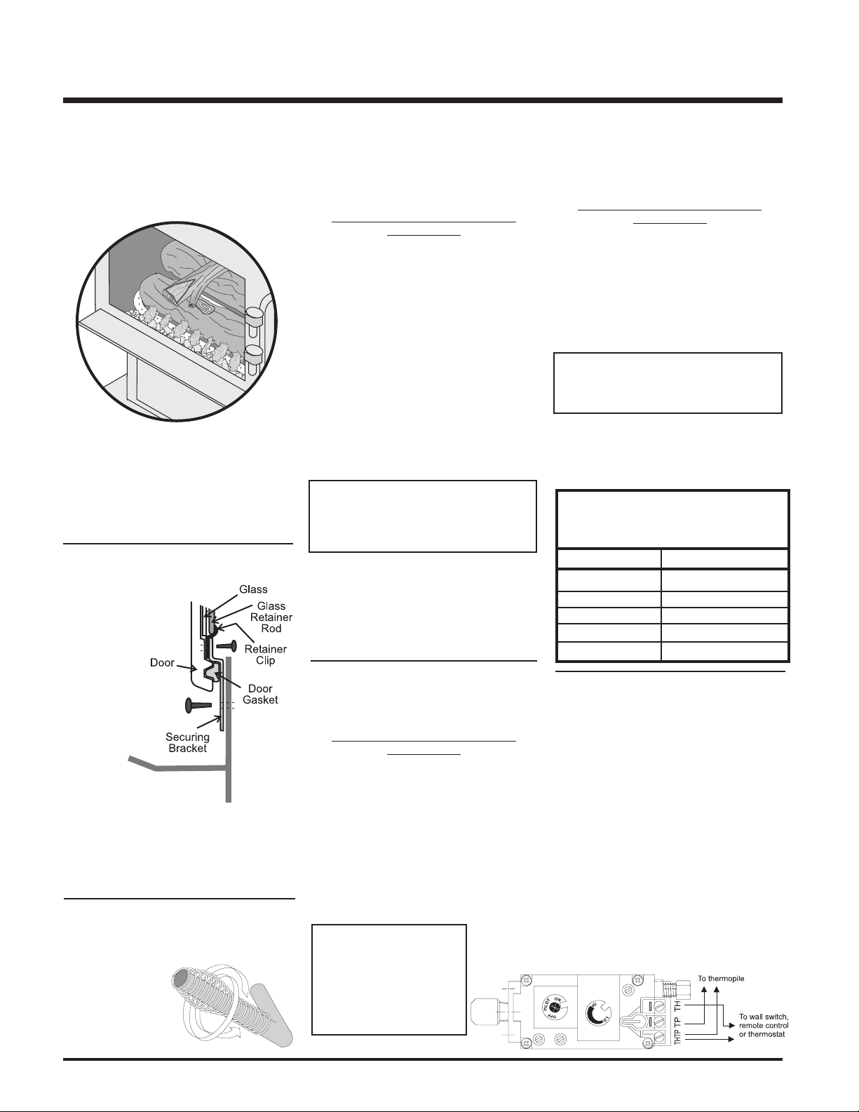
The gas log kit contains the following:
a) Front Log
b) Rear Log
c ) Small Cross Logs (2)
d) Bag of embers
e) Bag of rock wool
1) Remove the logs from the box and carefully
unwrap them. The logs are fragile,
handle with care. Do not force into
position.
2) Place the rear deflector on the rear log
support pins in the back of the unit.
3) Place the rear log into the rear of the firebox,
aligning the holes on the underside of the log
with the rear log support pins and carefully
push the log down onto the pins. See
diagrams 1 and 2.
4) Ensure the front deflector is over front log
pins. See diagram 1.
5) Place the front log in the front of the unit,
aligning the holes on the underside of the log
with the log support pins in the front of the
unit. Carefully push the log down onto the
pins. See diagram 1.
Diagram 1
6) Place the cross logs on top of the larger logs
aligning the holes on the underside of the
TEST FOR FLUE
SPILLAGE
This heater must be properly connected to a
venting system.
LOG SET
cross log with the log pins in the larger logs.
See diagrams 1 & 2. Carefully push the
cross logs onto the pins.
INSTALLATION
WARNING: Operation of this heater
when not connected to a properly
installed and maintained venting
system or tampering with the vent
safety shutoff system can result in
carbon monoxide (CO) poisoning
and possible death.
A “spillage” test must be made before the
installed unit is left with the customer. Follow
the procedure below:
Regency CLASSIC C33-2 Freestanding Gas Stove 11
WARNING: Dangerous operating
conditions may occur if these logs
are not positioned in their approved
locations. Read the instructions
below carefully and refer to the
diagrams. If logs are broken do not
use the unit until they are replaced.
Broken logs can interfere with the
pilot and burner operation.
Diagram 2
7) Distribute the embers along the mesh ember tray, but do not cover the burner ports.
(Burner ports are the little holes on the top
of the burner tube.) Pull off ember size
pieces from the rock wool. Gently place the
pieces on top of the embers. See diagram
3.
Page 12
INSTALLATION
Do not put the rock wool directly on the
burner. Close the door and turn the unit on
as per lighting instructions. Watch the
flame to see if it flows smoothly around
from one end to the other. (Use Extreme
Caution and ensure proper light off of
burner.)
Diagram 3
8) If the flame hesitates at any point, check the
area of hesitation and see if there is an
ember or rock wool blocking a burner port
or ports. If so, move the obstruction and
then check the flame flow again.
SAFETY LATCH
Secure door in the closed
position using the door
securing bracket and the
screw provided.
Note: Door securing
OPTION 1: REMOTE
CONTROL
INSTALLATION
Can be used with Options 2 or 3
but not both.
Use the Regency Remote Control Kit approved
for this unit. Use of other systems may void
your warranty.
The remote control kit comes with a hand held
transmitter, a receiver and a wall mounting
plate.
1) Choose a convenient location on the wall
to install the receiver (protection from
extreme heat is very important). Run
wiresfrom the fireplace to that location.
Use the Thermostat Wire Table.
2) Connect the two wires to the gas valve.
See diagram below.
CAUTION
Do not wire millivolt remote
control wires to the
120V AC wires
3) Install 3 AAA alkaline batteries in transmit-
ter and 4 AA alkaline batteries in the
receiver. Install the receiver and its cover
in the wall. Switch the remote receiver to
"remote" mode. The remote control is now
ready for operation.
OPTION 2: REMOTE
WALL SWITCH
Can be used with Options 1 or 3
but not both.
OPTION 3: WALL
THERMOSTAT
INSTALLATION
Can be used with Options 1 or 2
Regency offers an optional programmable thermostat but any 250-750 millivolt rated nonanticipator type thermostat that is CSA, ULC or
UL approved may be used.
Connect the wires as per the wiring diagram.
Use the Thermostat Wire Table to determine the
maximum wire length.
Do not wire millivolt wall thermo-
stat wires to the 120V AC wires
Note: Preferable if the thermostat is in-
stalled on an interior wall.
Recommended Maximum Lead Length
(Two-Wire) When Using Wall
Wire Size Max. Length
14 GA.
16 GA.
18 GA.
20 GA.
22 GA.
but not both.
CAUTION
Thermostat Wire Table
Thermostat (CP-2 System)
50 Ft.
32 Ft.
20 Ft.
12 Ft.
9 Ft.
FINAL CHECK
Before leaving this unit with the customer, the
installer must ensure that the appliance is firing
correctly. This includes:
bracket is there for
safety.
Note: The door must be kept closed at all
times, except during maintenance.
The unit must never be operated
without the glass in the door, or
with the door open.
DOOR HANDLE
Attach spring handle by rotating counter clockwise onto rod.
Ensure that the
spring fits into the
entire length of the
rod.
12
1) Run the wire through the opening in the rear
of the unit. Be careful not to damage any
wires.
Note: We recommend a maximum of 15'
of wire but if you wish to go with
a longer run use the Thermostat
Wire Table.
2) Connect the wire to the wall switch and
install into receptacle box.
CAUTION
Do not wire millivolt
wall switch for gas
appliance to the
120V AC wires
1) Clocking the appliance to ensure the correct
firing rate (rate noted on label) after 15
minutes.
2) If required, adjusting the primary air to ensure that the flame does not carbon. First
allow the unit to burn for 15 min. to stabilize.
3) Check for proper draft.
CAUTION: Any alteration to the product that
causes sooting or carboning that results in
damage to the unit is not the responsibility of the
manufacturer and will not be covered by the
warranty.
Regency CLASSIC C33-2 Freestanding Gas Stove
Page 13
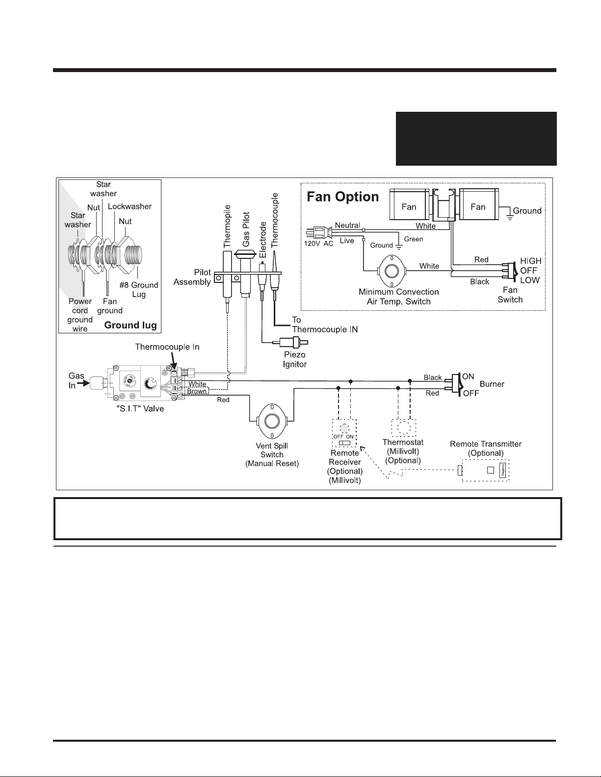
WIRING DIAGRAM
INSTALLATION
This heater does not require a 120V A.C. supply
for operation. In case of a power failure, the
burner switch and the optional remote control/
thermostat will continue to operate. However,
a 120V A.C. power supply is needed for the
fan/blower operation.
Caution: Ensure that the wires do
not touch any hot surfaces and are
away from sharp edges.
CAUTION: Label all wires prior to
disconnection when servicing controls. Wiring errors can cause improper and dangerous operation.
WARNING: Electrical Grounding Instructions
This appliance is equipped with a three pronged (grounding) plug for your protection against shock hazard and should be
plugged directly into a properly grounded three-prong receptacle. Do not cut or remove the grounding prong from this plug.
NORMAL OPERATING SOUNDS OF GAS APPLIANCES
It is possible that you will hear some sounds
from your gas appliance. This is perfectly
normal due to the fact that there are various
gauges and types of steel used within your
appliance. Listed below are some examples.
All are normal operating sounds and should
not be considered as defects in your appliance.
Blower:
Regency gas appliances use high tech blowers to push heated air farther into the room. It
is not unusual for the fan to make a "whirring"
sound when ON. This sound will increase or
decrease in volume depending on the speed
setting of your fan speed control.
Regency CLASSIC C33-2 Freestanding Gas Stove 13
Burner Tray:
The burner tray is positioned directly under the
burner tube(s) and logs and is made of a
different gauge material from the rest of the
firebox and body. Therefore, the varying thicknesses of steel will expand and contract at
slightly different rates which can cause "ticking" and "cracking" sounds. You should also
be aware that as there are temperature changes within the unit these sounds will likely reoccur. Again, this is normal for steel fireboxes.
Blower Thermodisc:
When this thermally activated switch turns ON
it will create a small "clicking" sound. This is the
switch contacts closing and is normal.
Pilot Flame:
While the pilot flame is on it can make a very
slight "whisper" sound.
Gas Control Valve:
As the gas control valve turns ON and OFF,
a dull clicking sound may be audible, this is
normal operation of a gas regulator or
valve.
Unit Body/Firebox:
Different types and thicknesses of steel
will expand and contract at different rates
resulting in some "cracking" and "ticking"
sounds will be heard throughout the cycling process.
Page 14

OPERATING INSTRUCTIONS
OPERATING
INSTRUCTIONS
1) The FIRST FIRE in your stove is part of the
paint curing process. To ensure that the
paint is properly cured, it is recommended
that you burn your fireplace for at least four
(4) hours the first time you use it with the
fan on. When first operated, the unit will
release an odour caused by the curing of
the paint and the burning off of any oils
remaining from manufacturing. Smoke detectors in the house may go off at this time.
Open a few windows to ventilate the room
for a couple of hours. The glass panel may
require cleaning.
Do Not Attempt To Clean The Glass
While it is still hot!
Note: When the glass is cold and the
appliance is lit, it may cause condensation and fog the glass. This
condensation is normal and will
disappear in a few minutes as the
glass heats up.
DO NOT BURN THE APPLIANCE
WITHOUT THE GLASS FRONT IN
PLACE.
2) Read and understand these instructions
before operating this appliance.
3) Check to see that all wiring is correct and
enclosed to prevent possible shock.
4) Check to ensure there are no gas leaks.
5) Make sure the glass in the door frame is
properly positioned. Never operate the
appliance with the glass removed.
6) Verify that the venting is unobstructed.
7) Verify log placement. If the pilot cannot be
seen when lighting the unit - the logs have
been incorrectly positioned.
8) The unit should never be turned off, and on
again without a minimum of a 60 second
wait for purging.
LIGHTING
PROCEDURE
IMPORTANT: Gas cock knob cannot be
turned from "PILOT" to "OFF" unless it is
partially depressed.
1) Turn burner OFF using "ON/OFF" switch.
2) Turn gas control knob so indicator points to
"OFF" position and allow 5 minutes for any
gas in the combustion chamber to escape.
3) Turn gas control knob counterclockwise so
indicator points to the "PILOT" position.
Depress the gas control knob fully. Depress the igniter button several times until
the pilot lights. After approximately one
minute, release the gas control knob. The
pilot flame should continue to burn. If the
pilot does not remain lit, repeat operation
allowing a longer period before releasing
gas control knob.
4) When the pilot stays lit, turn the gas knob
further counterclockwise to the "ON" position.
5) Use the ON/OFF switch, wall switch, thermostat or remote control to turn on the unit.
6) Rotate the flame height regulator (Hi/Lo) to
adjust the flame height higher or lower.
SHUTDOWN
PROCEDURE
1) Use the "ON/OFF" switch, wall switch,
thermostat or remote control to turn off the
burner.
2) Push in the PILOT knob slightly and turn
clockwise to "OFF". Do not force.
3) Turn off all electric power to the appliance
if service is to be performed.
MAINTENANCE
INSTRUCTIONS
1) Always turn off the gas valve before
cleaning. For relighting, refer to lighting
instructions. Keep the burner and control
compartment clean by brushing and vacuuming at least once a year.
When cleaning the logs, use a soft clean
brush as the logs are fragile and easily
damaged.
2) Clean appliance and door with a damp cloth
(never when unit is hot). Never use an
abrasive cleaner. The glass should be
cleaned with a gas fireplace glass cleaner
(when it starts to cloud up).
3) The heater is finished in a heat resistant
paint and should only be refinished with
heat resistant paint. Regency uses Stove
Brite Paint - Metallic Black #6309.
4) Make a periodic check of burner for proper
position and condition. Visually check the
flame of the burner periodically, making
sure the flames are steady; not lifting or
floating. If there is a problem, call a qualified
service person.
5) The appliance and venting system must be
inspected before use, and at least annually, by a qualified field service person, to
ensure that the flow of combustion and
ventilation air is not obstructed.
During the annual service call, the burners
should be removed from the burner tray
and cleaned. Replace the embers and rock
wool.
6) Each time the appliance is lit, it may cause
condensation and fog the glass. This
condensation is normal and will disappear
in a few minutes as the glass heats up.
7) Caution: Label all wires prior to disconnection when servicing controls. Wiring errors
can cause improper and dangerous operation. Verify proper operation after servicing.
14
WARNING: CHILDREN AND
ADULTS SHOULD BE ALERTED TO
THE HAZARDS OF HIGH SURFACE
TEMPERATURES AND SHOULD
STAY AWAY TO AVOID BURNS OR
CLOTHING IGNITION. YOUNG
CHILDREN SHOULD BE CAREFULLY SUPERVISED WHEN THEY ARE
IN THE SAME ROOM AS THE APPLIANCE.
Regency CLASSIC C33-2 Freestanding Gas Stove
Page 15

OPERATING INSTRUCTIONS
1) Push in the gas control knob slightly and turn
clockwise to “OFF”. Do not force.
FOR YOUR SAFETY READ BEFORE LIGHTING
A) This appliance has a pilot which must be lighted
by hand, following the instructions below
exactly.
B) BEFORE LIGHTING smell all around the appliance
area for gas. Be sure to smell next to the floor
because some gas is heavier than air and will
settle on the floor.
WHAT TO DO IF YOU SMELL GAS
- Do not try to light any appliance
- Do not touch any electric switch, do not use any
phone in your building
- Immediately call your gas supplier from a
neighbors phone. Follow the gas supplier’s instructions.
- If you cannot reach your gas supplier, call the
fire department.
C) Use only your hand to push in or turn the gas
control knob. Never use tools. If the knob will not
push in or turn by hand, don’t try to repair it, call
STOP! Read the safety information above on this
label.
1)
Push in gas control knob slightly and turn
clockwise
to “OFF”. Knob cannot be turned
from “PILOT” to “OFF” unless knob is pushed in
slightly. Do not force.
2) Wait five (5) minutes to clear out any gas. If you
then smell gas STOP! follow “B” in the safety
information above on this label. If you don’t smell
gas, go to the next step.
3)Turn knob on gas control counterclockwise
to “PILOT”.
4)Push in control knob all the way and hold in.
Immediately push black button on spark igniter
until pilot lights. Continue to hold the control
knob in for about 1/2 minute after the pilot is lit.
Release knob and it will pop back up. Pilot should
remain lit. If it goes out, repeat steps 3) and 4).
If knob does not pop up when released, stop and
immediately call your service technician or gas
supplier.
If the pilot will not stay lit after several tries, turn the
gas control knob to “OFF” and call your service
technician or gas supplier.
5) Turn gas control knob counterclockwise to “ON”.
6) Use rocker switch to operate main burner.
908-649a
OFF
WARNING: If you do not follow these instructions exactly, a fire or explosion may result
causing property damage, personal injury or loss of life. Improper installation, adjustment,
alteration, service or maintenance can cause injury or property damage. Refer to the
owner’s information manual provided with this appliance. For assistance or additional
information consult a qualified installer, service agency or gas supplier.
a qualified service technician. Force or attempted
repair may result in a fire or explosion.
D) Do not use this appliance if any part has been under
water. Immediately call a qualified service technician to inspect the appliance and to replace any part
of the control system and any gas control which has
been under water.
This appliance needs fresh air for safe operation and
must be installed so there are provisions for adequate
combustion and ventilation air.
LIGHTING INSTRUCTIONS
TO TURN OFF GAS APPLIANCE
THERMOPILE
ELEMENT
THERMO-
ELECTRIQUE
PILOT BURNER
VEILLEUSE
This appliance must be installed in accordance with local codes, if any; if not,
follow the current CAN1-B149/ANSI Z 223.1 (Australia: AG601, New Zealand: NZS 5261)
DO NOT REMOVE THIS INSTRUCTION PLATE
CAUTION: Hot while in operation. Do not touch.
Severe Burns may result. Due to high surface
temperatures keep children, clothing and
furniture, gasoline and other liquids having
fammable vapors away. Keep burner and control
compartment clean. See installation and
operating instructions accompanying appliance.
2) Turn off all electric power to the appliance if
service is to be performed.
You may shut off the pilot during prolonged non use periods to conserve fuel.
COPY OF THE LIGHTING PLATE INSTRUCTIONS
Regency CLASSIC C33-2 Freestanding Gas Stove 15
Page 16

MAINTENANCE
CAUTION: ANY SAFETY SCREEN
OR GUARD REMOVED FOR SERVICING AN APPLIANCE MUST BE
REPLACED PRIOR TO OPERATING THE APPLIANCE.
CLOTHING OR OTHER FLAMMABLE MATERIAL SHOULD NOT BE
PLACED ON OR NEAR THE APPLIANCE.
NEVER OPERATE THE APPLIANCE
WITHOUT THE GLASS PROPERLY
SECURED IN PLACE.
GENERAL VENT
MAINTENANCE
Conduct an inspection of the venting system at
least annually. Recommended areas to inspect
are:
1) Check areas of the Venting System which
are exposed to the elements for corrosion.
These will appear as rust spots or streaks,
and in extreme cases, holes. These components should be replaced immediately.
2) Remove the Cap, and shine a flashlight
down the Vent. Remove any birds nests, or
other foreign material.
THERMOPILE/
THERMOCOUPLE
1) Loosen the thermocouple or thermopile
with a 7/16" wrench at bracket.
2) Disconnect thermocouple by loosening nut
from the valve with a 9mm wrench. Disconnect thermopile by loosening 2 screws
marked TP on the valve.
3) Drop the thermocouple or thermopile down
from the bracket and pull it out of the unit.
4) Reinstall the new ones in reverse order.
AERATION
ADJUSTMENT
The aeration adjustment rod is attached to the
air shutter on the burner. The air shutter adjustment rod is located under the ashlip on the right
side. The rod is used to adjust the aeration on
the burner. This adjustment is performed by the
installer and is primarily used in installations at
high elevations. Push the rod in for a yellow
flame, or pull out on the rod for a bluer flame.
Air shutter opening:
Natural Gas 7/16"
Propane Wide open
PILOT ADJUSTMENT
Periodically check the pilot flames. Correct flame pattern has three strong blue
flames: 1 flowing around the thermopile,
1 around the thermocouple and 1 flowing
across the burner (it does not have to be
touching the burner).
Note: If you have an incorrect flame pat-
tern, contact your Regency dealer
for further instructions.
Top View of pilot flame
Incorrect flame pattern will have small,
probably yellow flames, not coming into
proper contact with the rear burner or
thermopile or thermocouple.
3) Check for evidence of excessive conden-
sation, such as water droplets forming in
the liner, and subsequently dripping out the
joints, Continuous condensation can cause
corrosion of caps, pipe, and fittings. It may
be caused by having excessive lateral
runs, too many elbows, or exterior portions
of the system being exposed to cold weather.
4) Inspect joints, to verify that no pipe sections
or fittings have been disturbed, and consequently loosened. Also check mechanical
supports such as Wall Straps for rigidity.
Top View of pilot flame
Closed - Tall Yellow flame
Open - Short Blue flame
Caution: Carbon will be produced if air
shutter is closed too much.
Note: Aeration Adjustment should only
be performed by an authorized
Regency Installer at the time of
installation or service.
16
Regency CLASSIC C33-2 Freestanding Gas Stove
Page 17

MAINTENANCE
LOG REPLACEMENT
The unit should never be used with broken
logs. Turn off the gas valve and allow the unit
to cool before opening door to carefully remove the logs. The pilot light generates enough
heat to burn someone.
If for any reason a log should need replacement, use only Regency replacement logs. The
position of these logs must be as shown in the
diagram under Log Installation.
NOTE: Improper positioning of logs may
create carbon build-up and will
alter the unit’s performance
which is not covered under warranty.
GOLD-PLATED DOORS
The 24 carat gold plated finish on the door
requires little maintenance, and need only be
cleaned with a damp cloth. DO NOT use
abrasive materials or chemical cleaners, as
they may harm the finish and void the warranty. Clean any fingerprints off before
turning the unit on.
GLASS
REPLACEMENT
Your CLASSIC stove is supplied with high
temperature, 5 mm Neoceram ceramic glass
that will withstand the highest heat that your
unit will produce. In the event that you break
your glass by impact, purchase your replacement glass from an authorized Regency dealer
only, and follow our step-by-step instructions
for replacement.
1) Allow the stove to cool before removing or
replacing glass.
2) To remove the door from the stove remove
the securing screw located between the
ashlip and the door, then unfasten the latch.
3) Remove gold hinge caps from door.
4) Lift door off hinge.
5) Lay door on a soft, flat surface.
6) Remove the screws in the glass retainer
clips and remove the glass retainer rod.
Remove any remaining pieces of glass and
ensure that the door is free of debris. Use
caution when removing broken glass to
avoid injury.
7) Install the replacement glass. When placing
the replacement glass in the door, make
sure that the glass gasketing will properly
seal your unit.
8) Put glass in place and then position glass
retainer rod.
Note: Do not use substitute materials. If
your glass does break, do not
continue to use your unit until it
has been replaced.
9) Position the glass retainer clips and door
securing bracket. Secure the glass retaining screws but do not overtighten as this
may cause the glass to break after the unit
heats up.
10)Tighten all screws evenly.
Note: Do not overtighten as this may
cause breakage.
11)Slip door over hinge pins.
12)Put hinge caps back onto door.
13)Close door and secure the security bracket
with the screw.
Regency CLASSIC C33-2 Freestanding Gas Stove 17
Page 18

MAINTENANCE
REMOVING VALVE
ASSEMBLY
1) Shut off gas supply.
2) If optional fan is installed, disconnect pow-
er source to stove.
3) Remove access panel.
a) Front panel on pedestal model. See
diagram 1.
b) Panel from bottom of leg shield. See
diagram 2.
Note: Access panel only has to be loos-
ened to be taken out.
Diagram 1
8) If optional fan is installed, remove thermodisc to bracket by removing three (3) phillips
head M5 screws.
9) Remove front cover with Piezo Igniter by
removing two (2) sheet metal screws.
10)Loosen four (4) phillips head M5 valve
mounting screws from underside of firebox. Push valve assembly forward on the
teardrop slots and drop down. Diagram 3.
Diagram 3
16)Remove inlet pipe with pipe wrench. Note
orientation of 90o elbow.
17)Remove two (2) phillips head M5 screws on
each side of the valve.
18)Remove valve and remove gas out 90
brass fitting. Note orientation of fitting.
INSTALLING VALVE
ASSEMBLY
1) To install a new valve assembly, reverse
instructions for removing valve. See
assembly steps 1-11.
2) Check for leaks and manifold pressure. See
Gas Pressure Test instructions.
3) To reinstall valve, reverse instructions for
removing valve assembly, steps 12-18.
o
Diagram 2
4) Disconnect gas line to stove.
5) Disconnect 3/8" NPT pipe from 90o elbow on
valve.
6) Disconnect the two (2) switch wires from
valve.
7) Remove two (2) orifice bracket screws
inside firebox.
18
11)Disconnect Piezo wire.
To remove valve from valve assembly,
continue.
12)Remove two (2) thermopile wires.
13)Remove thermocouple with a 9 mm (met-
ric) wrench.
14)Remove pilot nut with an 11 mm wrench.
15)Remove valve to orifice nut with a 13/16"
wrench.
Regency CLASSIC C33-2 Freestanding Gas Stove
Page 19

Part # Description
1) 846-913 Door Assy-Gold (no glass)
846-915 Door Assy-Black (no glass)
3) 846-302 Small Glass
4) 936-243 Glass Gasket (7/8")
5) 846-920 Glass Retainer Clips (8/set)
6) * Screw 1/4 - 20 x 3/8"
7) 948-170/P Small Glass Retainer
9) 846-973 Door Handle/Latch Assembly
10) 910-250 Spill Switch
12) 846-570 7/8" Gasket Repair Kit
13) 846-918 Hinge Cap - Gold (2/set)
14) * Screw #10 - 24 x 3/4"
15) * 1/4" split lock washer
16) * Screw #10 - 24 x 1/2"
17) 471-031 Door Retainer Clip
19) 948-101 Spring Handle - Large
490-917 Fan Assembly (120 V) Optional
20) 910-157/P Fan motor (120 V)
22) 910-794 Power Cord
910-140 Fan HI/OFF/LOW switch
28) 910-142 Fan Au to O N/ OFF The rm odi sc
PARTS LIST
MAIN ASSEMBLY
41) 460-006 Rear Panel
908-636 Manual
*Not available as a replacement part.
Regency CLASSIC C33-2 Freestanding Gas Stove 19
Page 20

PARTS LIST
Part # Description
52) 910-190 Piezo Ignit or & N ut
53) * Control Panel
908-672 Control Panel Decal
462-560/P Valve Assembly - S.I.T. - NG
462-561/P Valve Assembly - S.I.T. - LP
63) 910-378 Valve S.I.T. - NG
910-380 Valve S.I.T. - LP
66) 910-034 Pilot Assembly-3 flame-S.I.T. -NG
910-035 Pilot Assembly-3 flame-S.I.T. -LP
67) 904-604 Orifice #36 (NG)
904-390 Orifice #52 (LP)
68) 948-279 Burner - LP
69) 948-294 Burner - NG
70) 948-232 Air Shutter Adjusting Rod
* Burner Tray Assy-NG
* Burner Tray Assy-LP
72) 490-023 Deflector - Front Log
73) 460-009 Deflector - Rear Burner Front
74) 490-025 Deflector - Btm
Burner/Rear Log (LP)
75) 490-068 Rear Log Deflector Top
- Propane
79) 460-011 Deflector - Rear Burner
Back (NG)
80) 902-180 Front Log
81) 902-186 Rear Log
82) 902-182 Top Log (each)
BURNER & LOGS
93) 904-537 3/8 x 12" black mall nipple.
*Not available as a replacement part.
20
Regency CLASSIC C33-2 Freestanding Gas Stove
Page 21

BASE OPTIONS
Part # Description Part # Description
PARTS LIST
490-921 Complete Floor Shield
100) 948-216 Regency Logo
102) 904-257 Magnetic Catch (Large)
103) * 11" Pedestal Hinge
108) 910-246 Burner ON/OFF Switch (2-way)
109) 910-272 LT. Dummy Plug
110) * Strain Relief for power cord
121) * Access Panel
140) 850-126 Cast Legs - Black
850-127 Cast Legs - Gold
850-128 Cast Legs - Brush Nickel
142) 850-125 Steel Legs
490-926 Complete Pedestal
100) 948-216 Regency Logo
102) 904-257 Magnetic Catch (Large)
103) * 11" Pedestal Hinge
108) 910-246 Burner ON/OFF Switch (2-way)
109) 910-272 LT. Dummy Plug
110) * Strain Relief for power cord
123) * Pedestal Blanking Plate
124) 820-058 Pedestal Cover Plate
125) * Rear Cover Plate
*Not available as a replacement part.
Regency CLASSIC C33-2 Freestanding Gas Stove 21
Page 22

NOTES
_____________________________________________________________________________________
____________________________________________________________
__________________________________________________________
____________________________________________________________
_______________________________________________________
_____________________________________________________
__________________________________________________________
_________________________________________________________
_________________________________________________________
______________________________________________________
______________________________________________________
_______________________________________________________________
___________________________________________________________
__________________________________________________________
____________________________________________________________
____________________________________________________________
____________________________________________________________
_____________________________________________________________
__________________________________________________________
__________________________________________________________
_____________________________________________________
________________________________________________________
_________________________________________________________
_________________________________________________________
22
Regency CLASSIC C33-2 Freestanding Gas Stove
Page 23

WARRANTY
Regency Fireplace Products are designed with reliability and simplicity in mind. In addition, our internal Quality Assurance Team carefully inspects each
unit thoroughly before it leaves our facility. FPI Fireplace Products International Ltd. is pleased to extend this limited lifetime warranty to the original
purchaser of a Regency Product. This warranty is not transferable.
The Warranty: Limited Lifetime
The combustion chamber, heat exchanger, burner tubes/pans, logs and gold plating (against defective manufacture only) are covered under the Limited Lifetime Warranty
for five (5) years for parts and subsidized labour* and parts only thereafter.
Glass is covered for lifetime against thermal breakage only, parts and subsidized labour* for five (5) years and parts only thereafter from date of purchase.
Special Finishes - One year on brushed nickel, louvers and doors. You can expect some changes in color as the product "ages" with constant heating and cooling. FPI
warranties the product for any manufacturing defects on the original product. However, the manufacturers warranty does not cover changing colors and marks, ie. finger
prints, etc applied after the purchase of the product. Damage from the use of abrasive cleaners is not covered by warranty.
Electrical and mechanical components such as blowers, switches, wiring, thermodiscs, FPI remote controls, spill switches, thermopiles, thermocouples, pilot assembly
components, and gas valves are covered for one year parts and subsidized labour* from the date of purchase. Blowers and valves replaced under warranty are considered
repairs and continue as if new with appliance. ie. twelve (12) months from original purchase date of appliance with a minimum of three (3) months coverage from date
of replacement.
FPI venting components (Direct Vent units) are covered parts and subsidized labour* for three (3) years from date of purchase.
Simpson Dura-Vent venting components (Direct Vent units) are covered by Simpson Dura-Vent Inc. warranty.
Conditions:
Any part or parts of this unit which in our judgement show evidence of such defects will be repaired or replaced at FPI's option, through an accredited distributor or agent
provided that the defective part be returned to the distributor or agent Transportation Prepaid, if requested.
It is the general practice of FPI to charge for larger, higher priced replacement parts and issue credit once the replaced component has been returned to FPI and evaluated
for manufacturer defect.
The authorized selling dealer is responsible for all in-field service work carried out on your Regency product. FPI will not be liable for results or costs of workmanship
from unauthorized service persons or dealers.
At all times FPI reserves the right to inspect product in the field which is claimed to be defective.
All claims must be submitted to FPI by authorized selling dealers. It is essential that all submitted claims provide all of the necessary information including customer
name, purchase date, serial #, type of unit, problem, and part or parts requested, without this information the warranty will be invalid.
Exclusions:
This limited Lifetime Warranty does not extend to or include paint, door or glass gasketing or trim.
At no time will FPI be liable for any consequential damages which exceed the purchase price of the unit. FPI has no obligation to enhance or modify any unit once manufactured.
ie. as products evolve, field modifications or upgrades will not be performed.
FPI will not be liable for travel costs for service work.
Installation and environmental problems are not the responsibility of the manufacturer and therefore are not covered under the terms of this warranty policy.
Embers, glass and door gaskets, door handles and paint are not covered under the terms of this warranty policy.
Any unit which shows signs of neglect or misuse is not covered under the terms of this warranty policy.
The warranty will not extend to any part which has been tampered with or altered in any way, or in our judgment has been subject to misuse, improper installation, negligence
or accident, spillage or downdrafts caused by environmental or geographical conditions, inadequate ventilation, excessive offsets, negative air pressure caused by
mechanical systems such as furnaces, fans, clothes dryer, etc.
Freight damage to stoves and replacement parts is not covered by warranty and is subject to a claim against the freight carrier by the dealer.
FPI will not be liable for acts of God, or acts of terrorism, which cause malfunction of the appliance.
Performance problems due to operator error will not be covered by this warranty policy.
Products made or provided by other manufacturers and used in conjunction with the operation of this appliance without prior authorization from Regency, may nullify
your warranty on this product.
Any alteration to the unit which causes sooting or carboning that results in damage to the interior / exterior facia is not the responsibility of FPI.
* Subsidy according to job scale as predetermined by FPI.
Regency CLASSIC C33-2 Freestanding Gas Stove 23
Page 24
Regency fireplace products are designed
with reliability and simplicity in mind. In
addition, our internal Quality Assurance
Team carefully inspects each unit thor-
oughly before it leaves our door .
Fireplace Products International
Ltd. is pleased to extend this
Limited Lifetime Warranty to the orig-
inal purchaser of a Regency Product.
See the inside back cover for details.
Register your Regency online at
http://www.regency-fire.com
Installer: Please complete the following information
Dealer Name & Address:______________________________________________
__________________________________________________________________
Installer: ___________________________________________________________
Phone #: ___________________________________________________________
Date Installed: ______________________________________________________
Serial No.: _________________________________________________________
Regency and Classic are trademarks of FPI Fireplace Products International Ltd.
© Copyright 2005, FPI Fireplace Products International Ltd. All rights reserved.
Printed in Canada
 Loading...