


Planar 3
Old Motor Removal Instructions
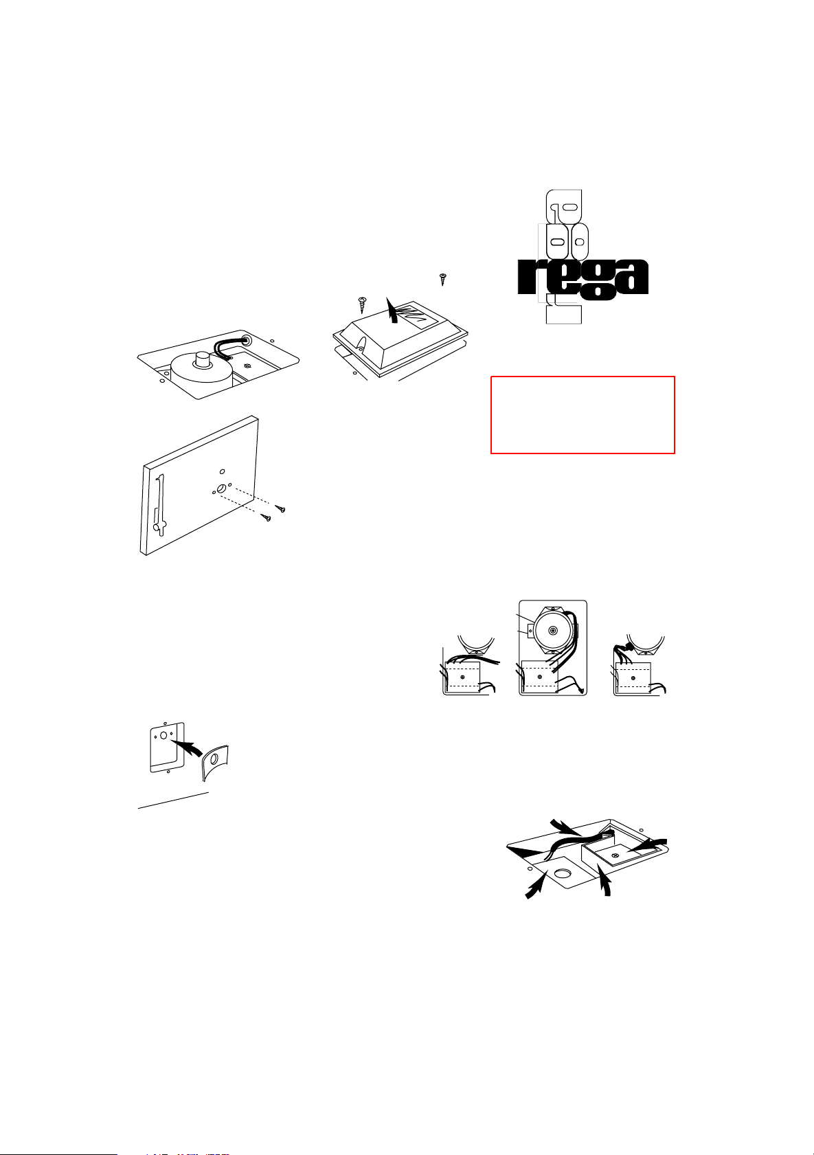
Firstly, remove the two black screws located on the motor cover
housing, then lift off the motor cover housing. Fig. 1
Remove the PCB mounting screw
located in the centre of the PCB.
The PCB will now be released
from its mounting. Fig. 2
De-solder the mains lead (Brown/Blue) from their eyelets. Also de-solder the
switch wires (White/White), so that no leads are left connected to the PCB,
except those of the motor itself. The PCB should now be free from the
turntable.
Undo the motor mounting screws (located on the top surface of the turntable
plinth Fig. 3) using a jewellers screwdriver. At the same time the motor must
be supported. The PCB and motor should now come out as one complete
unit.
New Motor Installation Instructions
You should now have an empty turntable with the wires
leading to the correct positions ready to take the new P3
PCB and motor assembly. Re-cut, strip and re-tin both of the
mains lead wires (Brown/Blue). On older variations please
loosen the mains lead knot, or remove the mains lead
grommet to aid motor installation. See Fig.4 for variations.
Now taking the sticky pad, stick it into the motor housing on the underside of the turntable
plinth making sure the pad is firmly secured, ensuring not to press too hard as the laminate
will crack. Steady judgement is required to ensure that the pad is concentric with the hol e
in the turntable plinth laminate. Fig. 5
The next thing is to fit the PCB tray making sure
that the mains lead is securely fixed to the clamp
to allow for soldering.
Re-sit the PCB tray on the existing mounting
block, ready to take the new PCB. Fig.6
Insert the PCB in such a way that the two eyelets
are nearest the mains flex that you have just
correctly adjusted. (Do not screw in). Now solder
the brown wire into the top eyelet and the blue
wire into the eyelet just below it.
Warning! Disconnect your
turntable from the mains
before attempting any work.
Do not operate turntable with
motor cover removed!
Planar 3 Upgrade Kit
Installation Instructions
Fig. 2
Remove two screws
Lift off case
Fig. 1
Remove two screws
Fig. 3
Switch Wires
Motor Mounting Plate
Motor
Brown (Live)
Blue (Neutral)
Blue
Red
Grey x2
Grey Red Blue
Grey Red Blue
Variations exist on some older motors
Fig. 4
Fig. 5
Mains Flex
PCB Tray
Sticky Pad
PCB
Fig. 6
 Loading...