

Page 1
REFERENCE
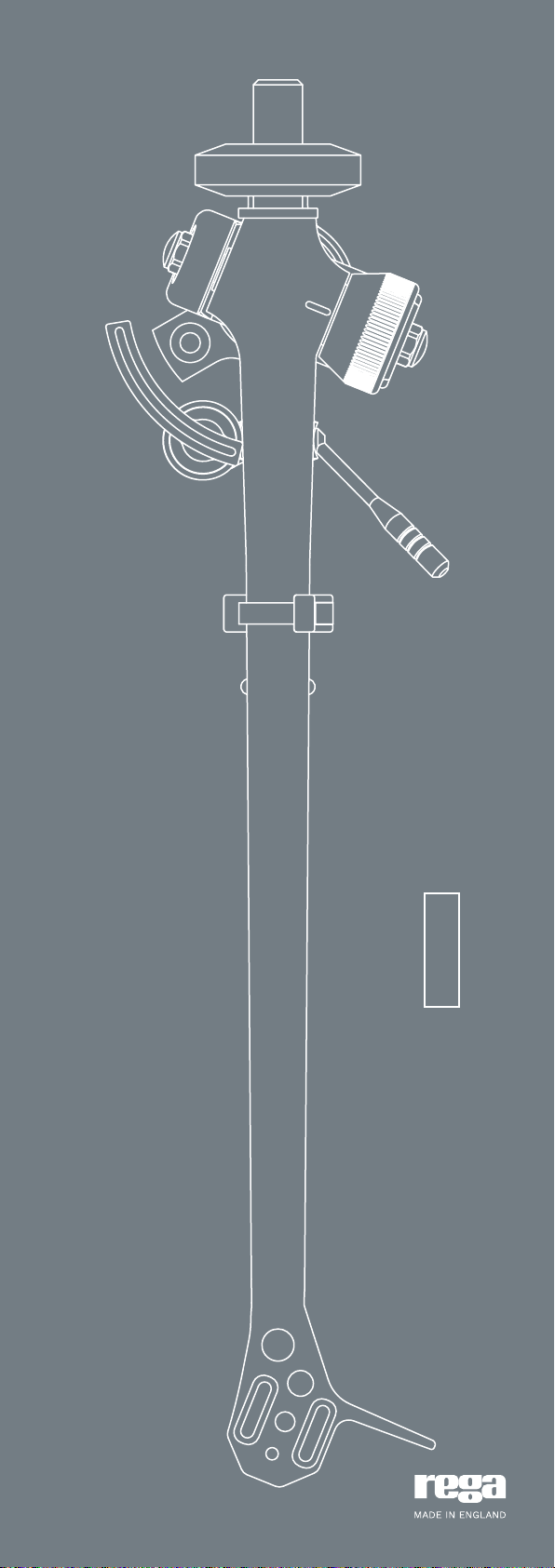
RB-Titanium Tonearm
User Manual & Mounting Data
Page 2

Introduction
The RB-Titanium tonearm is the most advanced and
accurate production tonearm we have ever released. The
entire tonearm structure is designed to have the minimum
of mechanical joints whilst using the stiffest materials in all
critical areas. The RB-Titanium achieves near frictionless
movement horizontally and vertically whilst having no
measurable free play in the bearing assemblies. The
RB-Titanium uses our unique one-piece titanium vertical
bearing housing and titanium vertical spindle assembly. The
design is completed with a Tungsten balance weight shaft
and balance weight.
Fitting your tonearm
The RB-Titanium will directly replace any other Rega
tonearm that currently uses the 3 point mounting, without
any modication. If tting to another manufacturers product
or an older Rega turntable (older RB models used a single
nut xing), the supplied template should be used as a guide
to ensure correct position and alignment. With so many
variants in turntable models, it is important to contact
your turntable manufacturer if in any doubt before making
any holes in plinths or arm boards. Before attempting to
t the RB-Titanium arm to the turntable, it is important
to ensure that there is sucient clearance beneath the
turntable and that the arm does not hit any dust cover, top
or sides. Having checked that there is sucient clearance
in all directions (including the maximum potential arm
movement horizontal and vertical), the next step is to nd
the position of the centre of the arm mounting hole. The
easiest way to do this will be to use the arm mounting
template supplied.
Using the RB-Titanium tonearm
Firstly, ensure the cartridge xings are orientated correctly
according to the cartridge makers specication. Use the
cartridge alignment protractor (supplied) to accurately set
the position of the cartridge.
Note: When using any Rega cartridge featuring a three-point
mounting system, overhang is automatically set.
With the cartridge correctly mounted and with the stylus
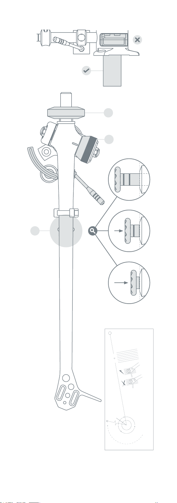
guard removed, ensure that the tracking force dial (A) and
bias adjustment (B) are set to zero. Adjust the balance
weight (C) until the arm is “oating” with the stylus
approximately 1mm clear of the record.
Note: It is normal for the arm to swing back towards the
arm clip position even with the bias set at zero. Therefore,
it is advisable to gently hold the arm bearing carrier
(just below the tracking dial) thus preventing horizontal
movement during the balancing procedure.
Once the arm is balanced, rotate the tracking force
adjustment dial to the required tracking force. Numbers ‘0’
to ‘3’ are marked on the dial. If in doubt, it is advisable to
use a tracking force that corresponds with the upper limits
of the cartridge manufacturer’s range.
Set the bias adjustment slider to the same gure as the
cartridge tracking force pressure quoted by your cartridge
manufacturer. Simply push the bias adjustment slider into
the required setting, using the dotted line as your reference.
Note: This is not critical and a gure between 1.0 & 1.5 will
normally be suitable for moving magnet cartridges and 1.5
& 2.0 for most moving coil cartridges.
Page 3
IMPORTANT:
Handle with care.
Cueing Platform
Balance Weight
C
Tracking Force Dial
A
0.0
B
1.0
2.0
Bias Adjustment Slider
Finger Lift
Headshell
Protractor and arm
mounting data
included.
Page 4

Arm mounting template guide
The supplied template is for mounting Rega three point
xing arms to other manufacturers turntables.
N.B. Protractor for cartridge alignment is also printed on the
same template.
1. The template should be kept at and not bent. The
distance between the centre of the spindle and the centre of
the arm hole is critical and must be 222mm. This template
will help you check your positioning before you attempt
tting and drilling.
2. Position the other end of the template so that the
clearance arc is within the rear and side edges of the
turntable base (and the lid when closed). Also check that
there is at least 250mm clearance from the centre of the
hole to the inside front of the turntable.
3. Use a long pointed probe such as a needle and push it
through the ‘arm hole centre’ on the template. Keep the
needle perpendicular to the template and mark the position
of centre on the turntable.
4. Having marked the centre, check again that if the arm
is placed in this position it will clear the under side of
the turntable and the lid. Also, check that the arm is in a
satisfactory position to ensure easy operation and that the
position is pleasing aesthetically. When you are certain
that the arm hole centre is in its correct position (exactly
222mm from the record centre), you can drill the required
arm hole.
5. The arm mounting pillar requires a diameter of 25mm
which will provide adequate clearance for accurate tting.
You can then drill the three screw mounting holes as
illustrated on the template. Make sure the arm is straight
and the holes are correctly aligned before drilling.
7. With the holes drilled, you are now ready to t the arm
to the turntable. Ensure that you also follow the turntable
manufacturer’s instructions regarding arm tting. Each
individual turntable manufacturer may have different
requirements regarding positioning of the arm signal lead.
Hardware mounting pack
The supplied hardware mounting pack is for tting the RB-
Titanium to other manufacturers turntables. The supplied
kit is suitable for most arm boards or mounting to wood-
based plinths (real wood/MDF/chipboard). In some cases,
you may need to source appropriate xings for more exotic
turntables.
regaresearch regaresearchuk Rega Research UK
Rega Research Ltd., 6 Coopers Way, Temple Farm Industrial Estate, Southend-on-Sea,
Essex, SS2 5TE
RB-Titanium User Manual | Version 1
 Loading...