

Page 1
INSTRUCTION MANUAL
Product No.
R20 - Fifth Wheel Hitch
You cantake it with you.
DEALER/INSTALLER:
(1) Provide this Manual to end user.
(2) Physically demonstrate hitching and unhitching
procedures in this Manual to end user.
(3) Have end user demonstrate that he/she
understands procedures.
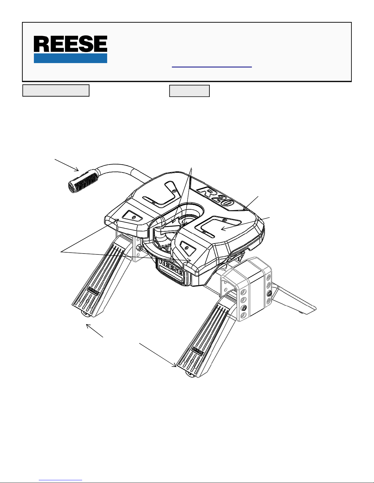
HANDLE
30867
END USER:
(1) Read and follow this Manual every time you use hitch.
(2) Save this Manual and Hitch Warning Hang Tag for future reference.
(3) Pass on copies of Manual and Hitch Warning Hang Tag to any other
user or owner of hitch.
JAWS TO HOLD KINGPIN
HEAD ASSEMBLY
LUBE PLATE
RAMP
SIDE BRACKETS
Page 2
WARNING:
Failure to follow these instructions may result in death or serious injury!
WARNING:
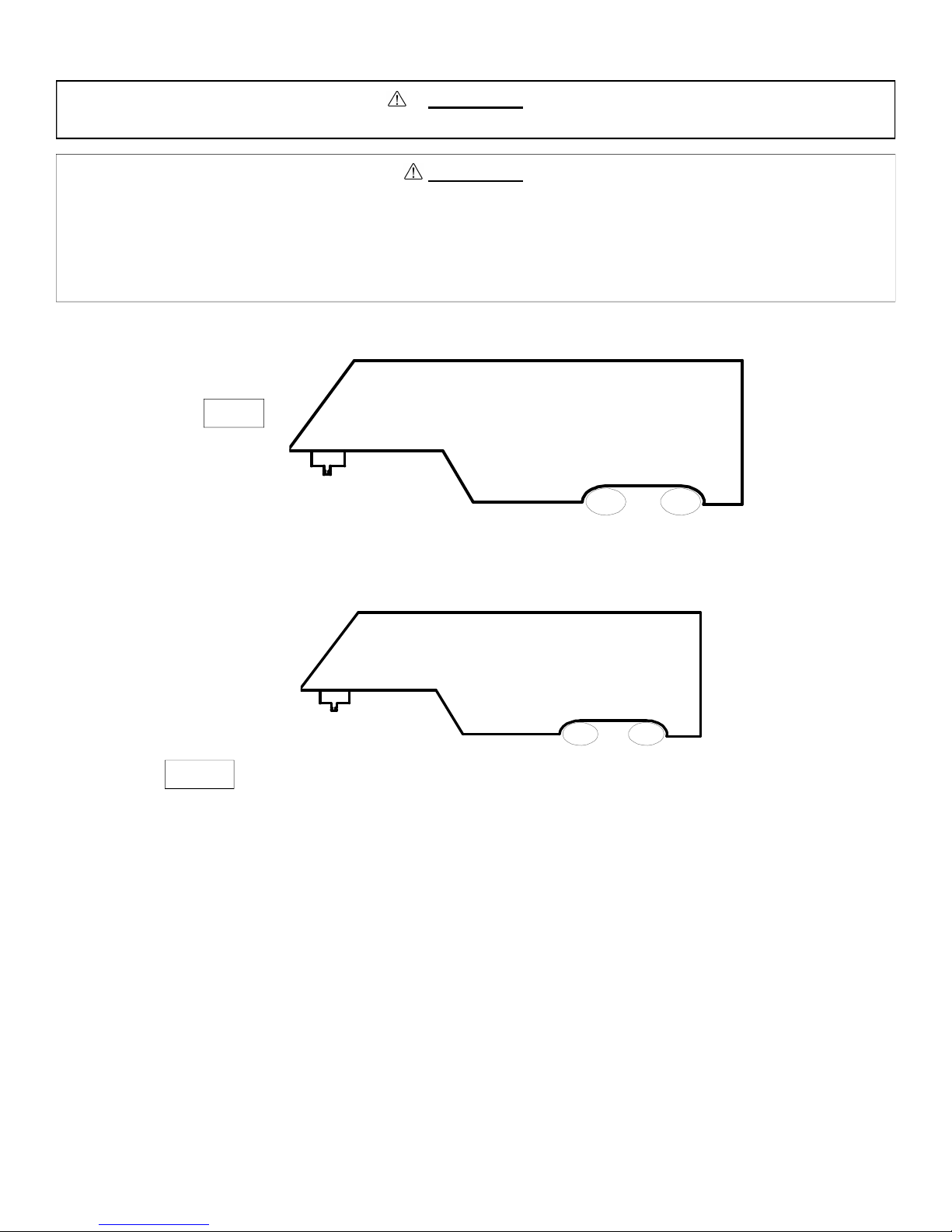
Trailer and its contents together must not exceed truck, hitch and/or trailer tow ratings.
Towing vehicle must have a manufacturer’s rated towing capacity equal to or greater than the gross trailer
weight (dry weight of the trailer plus payload of the trailer). (See Fig. 1)
Gross weight of trailer must not exceed 20,000 pounds.
King pin weight must not exceed 5,000 pounds (See Fig. 2). If in doubt have king pin weight measured by
qualified facility.
Fig. 1
1. Reese hitches are designed for use with recreational fifth wheel trailers only. Hitch applications other than recreational fifth
wheel trailers must be approved in writing by Reese’s Engineering Department.
2. Use only a SAE 2-inch king pin with your Reese Fifth Wheel Hitch.
3. Approximately 15%-25% of trailer weight should be on hitch (Pin Weight). See Fig 2.
GROSS TRAILER
Fig. 2
(PIN WEIGHT)
FACTORY TRAILER + FULL WATER TANKS + CARGO, ETC.
= GROSS TRAILER WEIGHT
15-25%
WEIGHT
GROSS TRAILER WEIGHT
75-85%
GROSS TRAILER
WEIGHT
Page 3
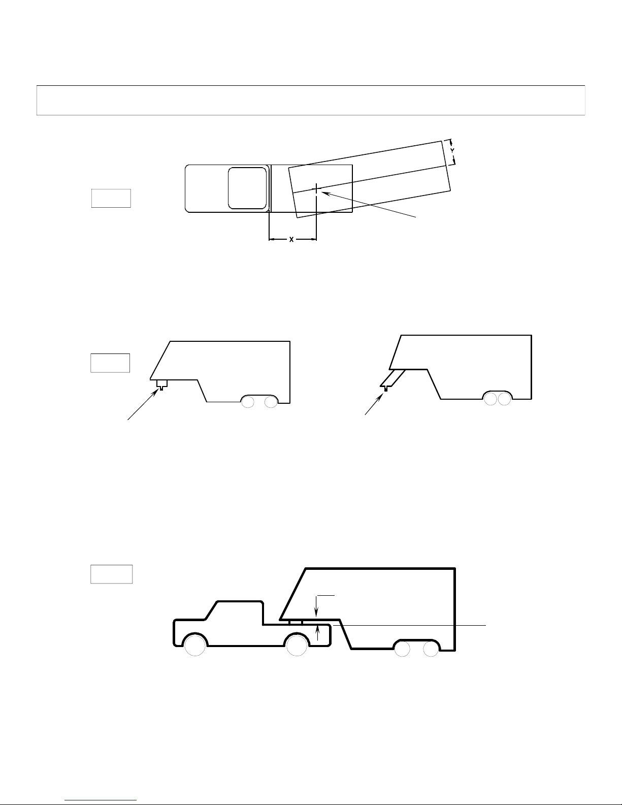
4. Trucks come in many different configurations. Reese hitches are designed for use in light trucks such as the Ford FSeries, the Chevy Silverado and the Dodge Ram. Reese recommends the use of long bed (8ft) light trucks for the best
combination in truck - trailer turning clearance.
Rule of thumb: The distance from the back of the truck cab to the center of the rear truck axle (“X” in Fig. 3), should be
approximately 4 inches greater than one-half the trailer width (“Y” in Fig.3)
RV TRAILER
Fig. 3
TRUCK
KING PIN
5. If a short bed pickup (less than 8 ft. but longer than 6 ft.) is to be used for towing, Reese recommends the trailer be
equipped with an extended pin box to help gain additional truck - trailer turning clearance (See trailer manufacturer for
options) (See Fig. 4). It also may be helpful to add a Reese Slider for increased turning clearance for low speed, nonhighway maneuvering.
Fig. 4
Conventional Pin Box
Extended Pin Box
6. The height of the hitch and the pin box should be adjusted so the trailer is approximately level as it is towed. Allow
approximately 6 inches clearance between the top of the pickup walls and the underside of the front of the trailer for pitch
and roll of the trailer. (See Fig. 5). Allow more clearance between pickup walls and trailer for off road use.
Fig. 5
.
Approximately 6 Inches
Level Trailer
Page 4

WARNING:
DO NOT use this hitch for towing a trailer with a pin box that could come in contact with or interfere with the
latch of the hitch handle when turning! (See Fig 6) If the pin box contacts the hitch handle or its latch when
turning, the trailer may become unhitched.
HANDLE
Fig. 6
ASSEMBLY INSTRUCTIONS
•Connection for trailer wiring should be in the side of the truck bed between the driver’s
seat and the wheel well for the back truck axle
•Installation of connection rearward of the wheel well may result in user placing body
between truck and trailer. WHENEVER POSSIBLE, AVOID PUTTING BODY UNDER TRAILER
OR BETWEEN TRUCK AND TRAILER!
•If you need to place any part of your body under trailer or between truck and trailer:
All trailer tires MUST be blocked in front and behind each tire AND
Trailer landing gear MUST be resting on firm ground AND
Truck MUST be stationary, in park, with emergency brake on!
KING PIN
BOTTOM OF PIN BOX
WARNING:
1. Reference Fig. 20 on back page. Number in parentheses refer to parts in Fig. 20.
2. R16 Fifth Wheel is contained in two cartons. Unpack and become familiar with parts on parts list. Base rail, brackets and
hardware are in separate kits (Part no’s. 30035, or 30095 or 30153) with separate installation instructions for Fifth Wheel Rail
Mounting Kit.
3. Place two base rails across bed of truck (See Fig 7). Select one leg and place tabs through the middle rectangular slot in the
base rails. Slip long pull pins through holes in base rails from the inside out as shown so the cotter pins are on the outside of
the base rails. Repeat for other leg. Secure pull pins with the spring retaining pins .
BASERAILS
Fig. 7
4. Select cross member (8) and install on leg aligning holes for hitch height desired. (Lowest position 14” highest 18”). Install four
½-13x4.5” Socket Head Cap bolts (9), with the heads towards the outside as shown, and lock nuts (10).
5. Torque ½” nuts to 75 lb.ft.
6. Install base rails and mounting brackets as described in “Installation Instructions for 5thWheel Rail Mounting Kit.”
Page 5

BEFORE EACH TRIP:
1. A plastic lube plate is supplied with the R20 (see figure on cover of Manual). Do not use automotive type chassis grease to
provide the lubricated surface.
2. DO NOT USE A ROUND LUBE PLATE WITH THE R20. A PLASTIC LUBE PLATE IS STANDARD EQUIPMENT ON THE
R20.
3. Before each trip or maneuver, operate the handle and check that the jaws open and close freely.
4. See that all hitch pins (#16 on Fig.20) are in place and the spring retaining pins (#17 on Fig.20) are installed.
HITCHING PROCEDURE:
IMPORTANT: YOU ARE RESPONSIBLE FOR SAFE HITCHING AND UNHITCHING OPERATIONS. DO NOT RELY ON
OTHERS TO PERFORM YOUR DUTIES. YOU MUST PERSONALLY MAKE SURE THE FOLLOWING
STEPS ARE PERFORMED IN THE FOLLOWING ORDER!
WARNING:
FAILURE TO FOLLOW THESE INSTRUCTIONS MAY RESULT IN DEATH OR SERIOUS INJURY.
1. Place blocks (sometimes called “chocks”) firmly against front and rear if each trailer wheel to prevent any possible forward or
rearward motion. DO NOT REMOVE BLOCKS UNTIL EACH OF THE FOLLOWING STEPS AND THE PULL TEST HAVE
BEEN COMPLETED. Lower tailgate if necessary.
2. Using trailer jacks, adjust trailer height following the directions in the trailer manual so that bottom of trailer pin (“A” in Fig. 6) is
½ to 1 inch below skid plate (See “B” in Fig. 8). During the hitching maneuver, the bottom of the trailer pin box should come in
contact with the skid plate ramp (“C” in Fig. 8).
Hitch Skid Plate (B)
Bottom of Pin Box (A) 1/2 To 1 Inch
Below Hitch Skid Plate (B)
Bottom of Pin Box (A)
Skid Plate Ramp (C)
Fig. 8
CORRECT
Bottom of Pin
Box Above
Hitch Skid Plate
Fig. 9
WRONG
WARNING:
Failure to follow this instruction may result in king pin being too high and coming to rest on top of closed jaws or
not completely inside jaws. (See Fig. 9). This could result in trailer separating from hitch. Trailer separation may
result in death or serious injury if anyone is under the trailer or between truck and trailer when separation occurs.
Page 6

3. Rotate hitch handle from locked position (see Fig. 10a) up to the unlocked position (See Fig 10b). This will unlock the jaw
system. NOTE: Hitch jaws will not open and proper hitching cannot occur if handle is NOT pointed up.
Fig. 10a
Fig. 11
LOCKED
King pin
UNLOCKED
Fig. 10b
Fig. 12
King pin
King pin Indicator – Out kingpin is
Locked in position
King pin
4. With handle in the unlocked position (See Fig. 10b), back truck slowly into trailer. As the trailer king pin enters the hitch it will
push the hitch jaws open and extend the handle (See Fig. 12). As king pin completely enters head, jaws will spring closed
around king pin and handle will return to the closed position and king pin indicator will extend out from the head assembly (See
Fig. 13).
5. After king pin is latched rotate handle down to ensure jaws are locked around king pin (See Fig. 14).
6. Use only the method described above for hitching.
Fig. 13
Fig. 14
WARNING:
Do not attempt to hitch by using trailer jacks to lower trailer and king pin. This could result in king pin coming to rest on top of skid
plate instead of within hitch opening where jaws are located. King pin could slide off hitch and trailer could drop, resulting in death
or serious injury.
Page 7

7. With all trailer wheels still firmly blocked, landing gear still resting on firm ground and supporting trailer weight, and truck
stationary and in park with the emergency brake on: visually check that bottom of pin box is resting on top of the hitch. THERE
SHOULD BE NO SPACE BETWEEN THESE SURFACES (See Fig 15). If space exists, (See Fig 16) trailer has not been
properly hitched. DO NOT TOW! Instead, repeat above steps until trailer is properly hitched. DO NOT PLACE BODY UNDER
TRAILER TO PERFORM THIS INSPECTION!
No Space
Fig. 15
CORRECT
8. To ensure that the jaws are locked and closed, the handle must be rotated in the down position (See Fig 17a). IF HANDLE
DOES NOT ROTATE DOWN, THE TRAILER HAS NOT BEEN PROPERLY CONNECTED TO HITCH. DO NOT TOW!
Repeat above steps until trailer is properly hitched. (See Fig 17b)
Fig. 17a
Fig. 17b
High Pin
Fig. 16
WRONG
9. With:
• All trailer wheels still firmly blocked in front and behind each tire, and
• Truck stationary with the emergency brake on, and
• Trailer landing gear still resting on firm ground and supporting trailer weight, and
• Truck stationary and with emergency brake on:
10. Connect electrical cable between truck and trailer, connect breakaway switch cable from pin box to a permanent part of truck,
and raise tailgate of truck.
•WHENEVER POSSIBLE, AVOID PUTTING BODY UNDER TRAILAER OR BETWEEN TRUCK AND TRAILER.
•If you need to place any part of your body under trailer or between truck and trailer:
•All trailer tires MUST be blocked in front and behind each tire AND
•Trailer landing gear MUSTbe resting on firm ground AND
•Truck MUSTbe stationary, in park, with emergency brake on!
HANDLE IN LOCKED
POSITION
WARNING
KING PIN
JAWS CLOSED
Page 8

PULL TEST
WARNING:
Failure to perform this test may result in death or serious injury!
1. With :
• All trailer wheels still firmly blocked, and
• Trailer landing gear still resting on firm ground and supporting trailer weight, and
• Truck stationary and with the emergency brake on:
• Return to cab of truck and release truck’s emergency brake. Apply trailer brakes. After making sure no one is
between truck and trailer, try to pull trailer slowly forward with the truck. If the trailer is properly hitched, the wheel
blocks and trailer brakes should keep the truck from moving forward.
NOTE: If trailer is not properly hitched, trailer will separate from hitch and truck will move forward leaving trailer behind. If the trailer
landing gear is still resting on firm ground supporting the trailer weight and wheel blocked, trailer will not be able to drop or fall.
WARNING:
Failure to keep wheels blocked and landing gear down could result in trailer suddenly moving or falling. This could result in death or
serious injury!
2. After successfully performing above steps, fully raise trailer landing gear (see trailer manual).
3. Check and inspect all electrical circuits for proper operation. (Clearance lights, turn signals, stop lights, etc.).
4. Remove and store all trailer wheel blocks.
UNHITCHING PROCEDURE:
PERFORM THE FOLLOWING IN THIS ORDER:
1. Place blocks firmly against front and rear of each trailer wheel to prevent any possible forward or rearward motion.
2. Using trailer jacks, lower trailer landing gear following the directions in the Trailer Manual until feet of landing gear are resting
on firm ground.
3. Make sure truck is in park with the emergency brake on.
WARNING:
Trailers that are not stable or properly hitched can fall and kill you! To avoid death or serious injury:
•All trailer tires MUST be blocked in front and behind each tire AND
•Trailer landing gear MUST be resting on firm ground AND
•Truck MUSTbe stationary, in park, with emergency brake on!
4. Lower truck tail gate.
5. Disconnect power cable and breakaway switch cable between truck and trailer.
6. Rotate hitch handle up to the unlocked position (See Fig 18) and pull the handle towards you so that the king pin is no longer
securely grasped by hitch jaws (See Fig 19 ). Trailer is now free from hitch and truck. If handle does not pull out, there is
probably pressure against the jaws. To relieve this pressure, back the truck slightly. Reset truck emergency brake. Then pull
hitch handle out completely.
Fig. 18
Fig. 19
Page 9

7. AFTER MAKING CERTAIN NO ONE IS STANDING BETWEEN TRUCK AND TRAILER OR IN FRONT OF TRUCK, drive truck
slowly away from trailer.
WARNING
Whenever possible, avoid putting body under trailer or between truck and trailer. If you need to place any part of your
body under trailer or between truck and trailer:
•All trailer tires MUST be blocked in front and behind each tire AND
•Trailer landing gear MUST be resting on firm ground AND
•Truck MUSTbe stationary, in park, with emergency brake on!
8. Close hitch jaws by pushing handle forward and rotating down.
9. KEEP WHEEL BLOCKS IN PLACE. This will keep trailer from moving unexpectedly
MAINTENANCE:
1. Recheck tightness of all hardware every 1000 miles of use.
2. See “Before each trip” section in this manual.
Page 10

FIGURE 20
1
14
2
3
15
4
5
4
12
13
7
7
10
11
17
5
6
8
9
ITEM NO DESCRIPTION PCS
1 HANDLE GRIP (1)
2 LUBE PLATE (1)
3 HEAD PAN ASSEMBLY (1)
4 HEAD PIN (2)
5 KLIK PIN (3)
6 1 1/4" CASTLE NUT (1)
7 SURGE ISOLATOR (2)
8 CROSS MEMBER (1)
9 1/2"-13 X 4.5" SOCKET HEAD CAP SCREW (4)
16
17
ITEM NO DESCRIPTION PCS
10 1/2" LOCK NUT (4)
11 SIDE BRACKETS (2)
12 PIVOT PIN (1)
13 PIVOT BEAM (1)
14 1/4"-20 SOCKET HEAD CAP SCREW (6)
15 HEAD ISOLATOR (2)
16 PULL PIN (4)
17 RETAINING CLIPS (4)
 Loading...