

Page 1
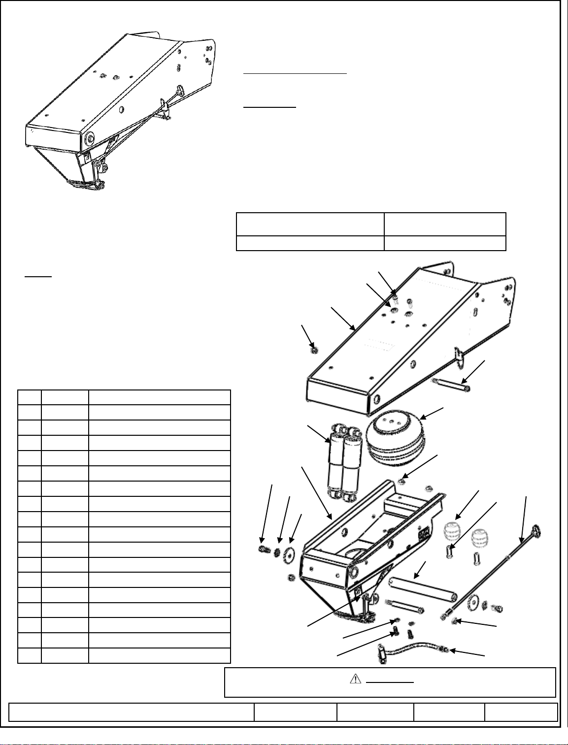
Equipment Required:
Fastener Kit: 94621F
Wrenches: 15/16”
Drill Bits: Not Required
Misc. : 15/16” Socket & Torque Wrench
Installation / Owners Manual
Goose Box
DEALER/INSTALLER:
(1) Provide this Manual to end user
END USER:
(1) Read and follow this Manual for Reese Goose Box Installation.
(2) Save this Manual for Future Reference.
(3) Pass on copies of Manual to any other users or owner.
Do Not Exceed Lower of Towing Vehicle Manufacturer’s Rating,
Trailer Manufacturer’s Rating or
Max Gross
Trailer WT (LB)
16,000 LB 3,200 LB
Part Number:
94621
94622*
*Packaged for Individual sale.
Max Pin
WT (LB)
INDEX
1. Explosion & Parts Identified P. 1
2. Guidelines For Matching Wing Sets P. 2
3. Guidelines For Matching P. 3
Tow Vehicle & Trailer
4. Assembly Into Wings P. 4
5. Hooking & UnHooking P. 4 & 5
6. Adjusting Air Suspension P. 6
7. 5 Year Limited Warranty P. 7
1 Qty. 1 Upper Body Weldment
2 Qty. 2 3/8 Conical Washer
3 Qty. 5 3/8-16x1 Grd.5 Bolt
4 Qty. 2 ½-13 NyLock Nut
5 Qty. 2 ½-13x6.5 Grd.5 Bolt
6 Qty. 2 Shock
7 Qty. 1 Double Air Bag
8 Qty. 3 3/8-16 Flanged Lock Nut
9 Qty. 2 Hollow Rubber Springs
10 Qty. 2 3/8-16x1.5 Socket Head Bolt
11 Qty. 1 Pull Cable
12 Qty. 1 Lower Jaw Weldment
13 Qty. 2 Large Zinc Washer
14 Qty. 2 ½ Internal/External Lock Washer
15 Qty. 2 ½-13x1.25 Grd.5 Bolt
16 Qty. 1 Pivot Shaft
17 Qty. 1 Air Line Assy’ w/Relief Valve
18 Qty. 2 3/8 Split Lock Washer
15
Figure 1
4
6
12
14
13
3
3
2
1
5
7
8
9
16
18
17 3
10
8
11
WARNING
Failure to follow all of these instructions may result in death or serious injury!
2009 Cequent Performance Products, Inc Sheet 1 of 7 94621IN 3/6/2012 Rev. C
Form: F205 Rev A 5-6-05
Page 2
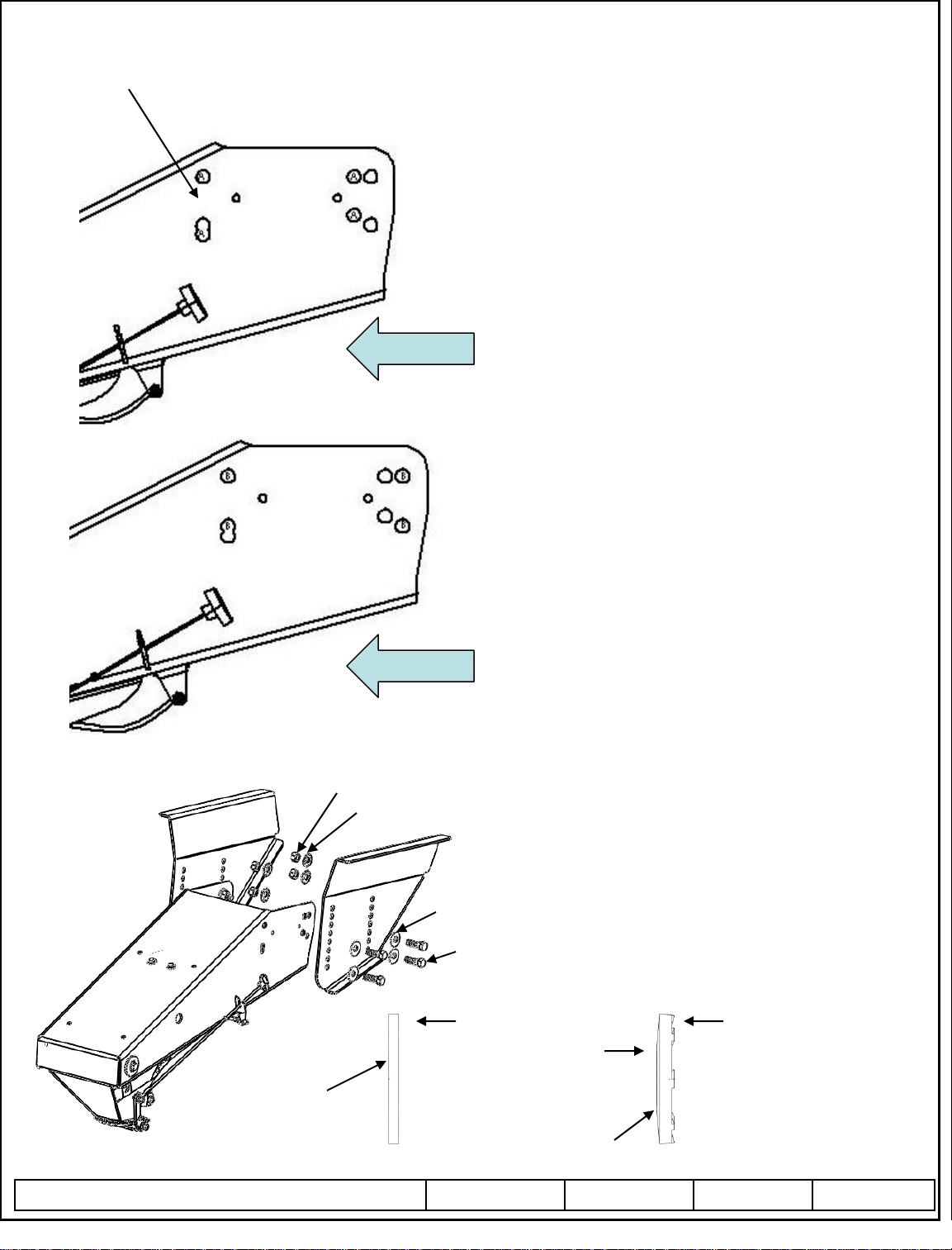
1621HD
Additional
Hole
Installation / Owners Manual
Goose Box
Matching Wing Sets
Figure 2
Figure 3
x
Trailer Forward
Trailer Forward
For Wing Set Make and Model Numbers:
Lippert 1621
Lippert 1621HD Check Trailer Rating
(1621HD unit will require additional hole to be drilled)
(Match drill hole to wing. Approximate location noted by the “x”)
Lippert 0719 Check Trailer rating
Fabex PB-600 Series Check Trailer Rating
Use The Bolt Hole Locations Noted By The “A”
The pattern is a 7.875” horizontal & a 2” vertical
Note: It is recommended that you install the Goose Box
one (1) position lower than the original pin box.
For Wing Set Make and Model Numbers:
Lippert 1716
Lippert 1116 Check Trailer Rating
Lippert 0115 Check Trailer Rating
Use The Bolt Hole Locations Noted By The “B”
The pattern is a 8.75” horizontal & a 2.5” vertical
Note: Spacer Kit 61301 Is Needed For These Model Wings
Please Refer To The Instructions In Kit 61301 For
Installation Of The Spacer Kit.
Note: It is recommended that you install the Goose Box
one (1) position lower than the original pin box.
Typical Bolting
Hardware Kit Contains: (8) 5/8-11x2 Gr.8 Bolts
5/8-11 Grd. 8 Nut
5/8 Conical Washer
Figure 4
5/8 Flat Washer
5/8-11x2 Grd.8 Bolt
Typical Flat
Washer,
5/8 Flat Washer
2009 Cequent Performance Products, Inc Sheet 2 of 7 94621IN 3/6/2012 Rev. C
Install On
Outside Of
Wing.
(8) 5/8-11 Gr.8 Nuts / (8) 5/8 HD Flat Washers
(8) 5/8 Conical Lock Washers
Bolts & Flat Washers Are Installed From The Outside,
Conical Lock Washers and Nuts On the Inside.
Torque All To 210 ft. lbs.
Note: The Figure Shows a Typical Installation
The Wing Is Moved Away To Better
Show The Hardware Installation.
Typical Conical Washer,
Nut
Side
5/8 Conical Washer
Note Crowned Shape &
Teeth. Install On Inside
Of Pin Box With Teeth
Against Inside Of Pin Box.
Form: F205 Rev A 5-6-05
Page 3
Installation / Owners Manual
Goose Box
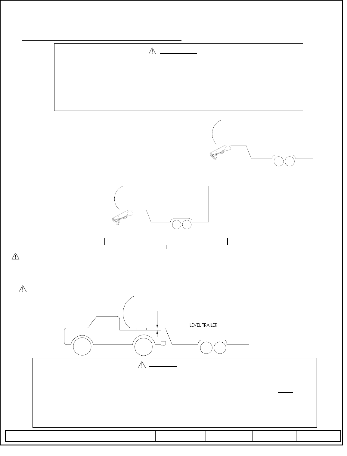
GUIDELINES FOR MATCHING TOW VEHICLE AND TRAILER
WARNING:
Failure to check and follow tow ratings could result in tow vehicle damage or truck
and trailer separation while towing.
Trailer and its contents together must not exceed truck, hitch and/or trailer tow ratings.
Towing vehicle must have a manufacturer’s rated towing capacity equal to or greater than
the gross trailer weight (dry weight of the trailer plus payload of the trailer). (See Fig. 5)
Gross weight of trailer must not exceed 16,000 pounds for this product.
Goose Ball vertical weight must not exceed 3,200 pounds (See Fig. 6). If in doubt have
Goose Ball weight measured by qualified facility.
1. Check Tow Ratings:
Vehicle Tow Rating: ________________.
Goose Box Rating:______________.
*Gross Trailer Weight (Figure 5):________________.
*Trailer weight should be the lowest of these recorded ratings for safe towing conditions.
2. The Goose Box is designed for a maximum of 20% Gross Trailer Weight on the Ball (Goose Ball Vertical Weight). See Fig. 6
Figure 6
20% MAX. GROSS
TRAILER WEIGHT
(BALL WEIGHT)
3. The Height of the Goose Box should be adjusted in the wing set so there is a minimum 7 in. clearance between the top of the bed
and the underside of the front of the trailer for pitch and yaw of the trailer (See Figure 7). This should be checked with the Goose
Box air bag inflated to 40psi. It is recommended that the Goose Box be mount in the wing set one position lower than the original
Pin Box.
For off-road use allow more clearance between pickup walls and trailer.
16,000 lbs.
Figure 5
80% GROSS
TRAILER WEIGHT
FACTORY TRAILER + FULL
WATER TANKS + CARGO, ETC.
= GROSS TRAILER WEIGHT
Figure 7
WARNING:
Avoid putting any part of your body under the trailer or between the truck and trailer. Unexpected or
accidental movement of the truck or the trailer can cause serious injury or death
If you must place any part of your body under the trailer or between the truck and trailer you MUST
perform ALL of the following steps:
Check that the truck transmission is in park
Check that the emergency brake is set
Block in front of and behind all trailer tires
Check that the trailer landing gear are resting on firm ground
2009 Cequent Performance Products, Inc Sheet 3 of 7 94621IN 3/6/2012 Rev. C
A MINIMUM
OF 7 IN. W/Air
Form: F205 Rev A 5-6-05
Page 4

Installation / Owners Manual
Goose Box
ASSEMBLY INSTRUCTIONS
1. Before removing the original pin box, take note of height of the original pin box, use this as a starting reference point for the
height of installing the Goose Box into the mounting wing set. (See Figure 8) The Goose Box comes with all new hardware to
be used. There is enough hardware for four bolts per side. Refer back to Figure 4 for bolt, washer, and nut installation.
Figure 8
Mounting Wing Set
2. Remove the existing pin box, taking care to remove any necessary wiring and/or break away switch if attached to the
pin box. (If removed, the break away switch and wiring must be reinstalled after installation is complete. The break
away switch can be mounted on the side of the Goose box or side of wing, but Do NOT drill or screw on the side of the
Goose Box forward of the air fill bracket.)
3. Install the Goose Box inside the mounting wings (Figure 9), Cequent Performance Products recommends using the hardware kit
included with the Goose Box. (4 bolts per side, 2 front row & 2 rear row) It is all grade 8 hardware. Install at least the hardware
included as a minimum. Torque all bolts to 210 ft. lbs.
Figure 9
Note: Installing the front top bolt of the Goose Box first may ease alignment.
Note: It is recommended that you install the Goose Box
one (1) position lower than the original pin box.
WARNING: The Goose Box is heavy, take care to maintain adequate
support under the Goose Box arm until at least 2 bolts per side are installed.
Failure to do so may result in death or serious injury.
HOOKING & UNHOOKING INSTRUCTIONS
When hitching and unhitching the trailer to the towing vehicle, you must do all of the following:
1. Block all trailer tires, in the front and behind.
2. Make sure that the trailer landing gear (trailer jacks) are resting on firm ground.
3. Make sure the truck is stationary, in park, with the emergency brake on.
2009 Cequent Performance Products, Inc Sheet 4 of 7 94621IN 3/6/2012 Rev. C
Form: F205 Rev A 5-6-05
Page 5

Installation / Owners Manual
Goose Box
WARNING:
Unstable or improperly hitched trailers can fall or separate and cause serious injury or death:
Never attempt to hitch trailer without first reading and following all instructions in the manual provided
with this product. Do not use without reading and understanding the manual.
Never tow a trailer that exceeds rated capacity. Towing a trailer that exceeds rated capacity can result in
trailer separation, serious injury, or death.
Never allow any part of the body to be placed under the trailer or between the truck and trailer.
The combined weight of the trailer and its contents must not exceed the lowest truck, hitch, and/or trailer
tow rating. Keep hands clear when operating coupler mechanism.
HOOKING-UP:
1. Use only with 2 5/16” dia. Gooseneck Ball.
2. Ensure coupler handle is in the full forward position and not limited by the pull cable. (Figure 10)
3. Lower coupler onto gooseneck ball. Handle will open, then snap shut.
4. Make certain handle has returned forward and is in the locked position before towing.
Figure 10
Pull Cable Handle
Handle In Locked
Position
UNHOOKING:
1. Using pull cable, pull handle back and hook cable into stop. (Figure 11) Handle should be in the Un-Locked position.
2. Note: If necessary you can adjust the cable stop by loosening the small set screw, moving stop, and then retightening.
3. Raise trailer off of gooseneck ball, then release cable. (Figure 10)
4. Ensure latch remains in locked position.
Figure 11
Handle In Un-Locked
Position
Adjustable Cable Stop
Pull Cable Hooked
In Cable Stop
2009 Cequent Performance Products, Inc Sheet 5 of 7 94621IN 3/6/2012 Rev. C
Form: F205 Rev A 5-6-05
Page 6

Installation / Owners Manual
Goose Box
MAINTENANCE:
1. Grease coupler shaft from fitting in back of coupler before each use and grease goose ball before each use..
2. Keep Goose Box painted to prevent rust and maintain a good appearance. (Do Not Paint Over Labels)
3. No special instructions for storage, perform normal maintenance when taking out of storage and using again.
ADJUSTING THE AIR SPRING
1. Perform the hitching procedure before adjusting suspension air pressure.
2. With trailer hitched to truck and landing gear / jacks retracted, Add air to the air spring at the valve shown in figures 12A, B, & C.
3. Continue adding air until the label on the rear driver’s side is in the green. (Figure 12C)
Note: Do NOT exceed 50 psi. Starting Operating Pressure Should Be Around 35-40 psi.
4. It may be helpful to put tow vehicle in drive, move a few inches, and then apply brake.
This will jounce the unit and let it find it’s natural position.
5. Recheck Air
The label is a good reference for setting air pressure in the spring, if more performance is desired the air bag
pressure can be adjusted to suite your preference. A good starting point for pressure setting is 35-40 psi.
(Do Not Exceed 50 psi). If the ride is too soft, add more pressure. If the ride is harsh, remove pressure.
Figure 12 A
Figure 12 C
BEFORE EACH TRIP:
Air Bag Fill
Fill Label Showing
To High On Pressure
Past Yellow Area
Air Bag Fill
Fill Label Showing
In Green Area
Pressure Is OK
Figure 12 B
Air Bag Fill
Fill Label Not Showing
To Low On Pressure
In Lower Yellow Area
Note:
The Goose Box is equipped with an
automatic air relief valve. If you try to
over inflate the bag the relief valve will
pop, releasing excess air. The system can
help you adjust the air bag. Fill to green
area, and then add a few more pounds of
air pressure. Drive your unit and step on
the brake a few times. Excess air will vent
off. You should be left with the unit near
or in the green area. This should be your
most optimum air pressure.
1. CHECK YOUR EQUIPMENT: Check that condition of all of your towing equipment and keep it in top condition.
2. Check to see that all bolts are properly tightened.
3. Check that the airbag pressure is set for your coach. (The label in rear should be in the green zone.)
2009 Cequent Performance Products, Inc Sheet 6 of 7 94621IN 3/6/2012 Rev. C
Form: F205 Rev A 5-6-05
Page 7

NOTES:
Installation / Owners Manual
Goose Box
LIMITED FIVE YEAR WARRANTY
1. Limited Warranty. Cequent Performance Products, Inc. (“We” or “Us”) warrants to the original consumer purchaser only
(“You”) that the product will be free from material defects in both material and workmanship for a period of five years, ordinary
wear and tear excepted; provided that installation and use of the product is in accordance with product instructions. There are no
other warranties, express or implied, including the warranty of merchantability or fitness for a particular purpose. If the
product does not comply with this limited 5 year warranty, Your sole and exclusive remedy is that We will replace the product
without charge to You and within a reasonable time or, at our option, refund the purchase price. This warranty is not
transferable.
2. Limitations on the Warranty. This limited warranty does not cover: (a) normal wear and tear; (b) damage through abuse,
neglect, misuse, or as a result of any accident or in any other manner; (c) damage from misapplication, overloading, or improper
installation, including welds; (d) improper maintenance and repair; and (e) product alteration in any manner by anyone other than
Us, with the sole exception of alterations made pursuant to product instructions and in a workmanlike manner.
3. Obligations of Purchaser. To make a warranty claim, contact Us at 47912 Halyard Drive Suite 100, Plymouth, MI, 48170,
1-888-521-0510, identify the product by model number, and follow the claim instructions that will be provided. Any returned
product that is replaced or refunded by Us becomes our property. You will be responsible for return shipping costs. Please retain
your purchase receipt to verify date of purchase and that You are the original consumer purchaser. The product and the purchase
receipt must be provided to Us in order to process Your warranty claim.
4. Remedy Limits. Repair or replacement is Your sole remedy under this limited warranty or any other warranty related to the
product. We shall not be liable for service or labor charges incurred in removing or replacing a product or any incidental or
consequential damages of any kind.
5. Assumption of Risk. You acknowledge and agree that any use of the product for any purpose other than the specified use(s)
stated in the product instructions is at Your own risk.
6. Governing Law. This limited warranty gives You specific legal rights, and You also may have other rights which vary from state
to state. This limited warranty is governed by the laws of the State of Michigan, without regard to rules pertaining to conflicts of
law. The state courts located in Oakland County, Michigan shall have exclusive jurisdiction for any disputes relating to this
warranty.
Cequent Performance Products - Towing Division
47912 Halyard Drive Suite 100
Plymouth, MI 48170
2009 Cequent Performance Products, Inc Sheet 7 of 7 94621IN 3/6/2012 Rev. C
Form: F205 Rev A 5-6-05
 Loading...