

Page 1
Installation Instructions
Item
Description
Quantity
Item
Description
Quantity
NUT, HEX 1/2"
BOLT CAR 5/8"
WASHER CONICAL 1/2"
BLOCK 5/8" x 1
WASHER FLAT 1/4" (Figure 3c)
SPACER 1/4" x 1 1/2" x 3"
NUT, NYLOK 1/4"
LOCKWASHER 5/8" PLATED
BOLT, HEX HEAD 1/4"
NUT, HEX 5/8"
DRIVER'S
CLAMP FRONT
PASSENGER'S SIDE FRAME BRKT
BOLT CAR 1/2"
CUSTOM QUICK INSTALL MOUNTING KIT
Part Number:
56005
FOR 30153 REESE® RAILS ONLY
1999 To 2010 Ford Super Duty F-250/F-350 & 2008 To 2010 F-450
WARNING: Under no circumstances do we recommend exceeding the towing vehicle manufacturers recommended vehicle towing
capacity.
READ ALL INSTRUCTIONS BEFORE STARTING THE INSTALLATION
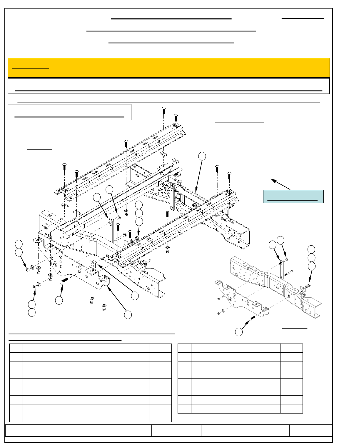
REESE® Custom Quick Install mounting brackets only include the hardware to attach the custom brackets to the frame.
10 BOLT INSTALLATION
Equipment Required:
Fastener Kit: 56005F
Wrenches: 3/4, 7/8, 15/16, 15 mm
Figure 1
2008 – 2010 shown
15
Drill Bits: 1/8”, 9/16”
Other Tools: Center Punch, Measuring Tape
8
7
13
12
11
1
2
1
9
2
Fasteners listed below are supplied with this kit, all other unidentified
fasteners are supplied with part number 30153.
1
2
3
4
5
6 L-BRACKET (Figure 3c) 1 14
7
8
©2012 Cequent Performance Products, Inc.
-13 4 9
4 10
2 11
-20 (Figure 3c) 1 12
-20 x 1 1/4" Grade 2 (Figure 3c) 1 13
2 15
-13 X 4.5" Grade 8 4
10
14
Vehicle Forward
All Fasteners
Typical Both Sides
8
7
13
12
11
Figure 2
9
-11 X 2-1/2" Grade 8 2
-1/2" x 2-1/8" 2
2
-11 Grade 8 2
SIDE FRAME BRKT 1
Sheet 1 of 5 56005N 2/16/2012 Rev. A
1999 – 2007 shown
2
1
Page 2
Installation Instructions
Part Numbers:
1999 To 2010 Ford Super Duty F-250/F-350 & 2008 To 2010 F-450
Do not install mounting rails over plastic bed liners. Plastic bed liners must be cut out of the
way to provide metal to metal contact. Mounting rails may be installed on spray in liners.
Use only bolts, nuts, and washers supplied to install this kit. All nuts & bolts are Grade 8 unless
otherwise specified.
These instructions are guidelines only, actual installation is the responsibility of the installer
and the owner. Always measure truck and trailer before installing fifth wheel hitch to be sure
that there is clearance at the cab and at the bumper to allow for turns.
Driver’s side
frame rail
Figure 3a
Inside of frame rail
Installation Instructions
CUSTOM QUICK INSTALL MOUNTING KIT
5
3
3
4
Figure 3c
Tube
holder
Driver’s side
frame rail
Existing
flange nut
Vapor
tube
Figure 3b
56005
Existing
flange nut
6
1. Lower and remove spare tire if extra room is needed for the installation.
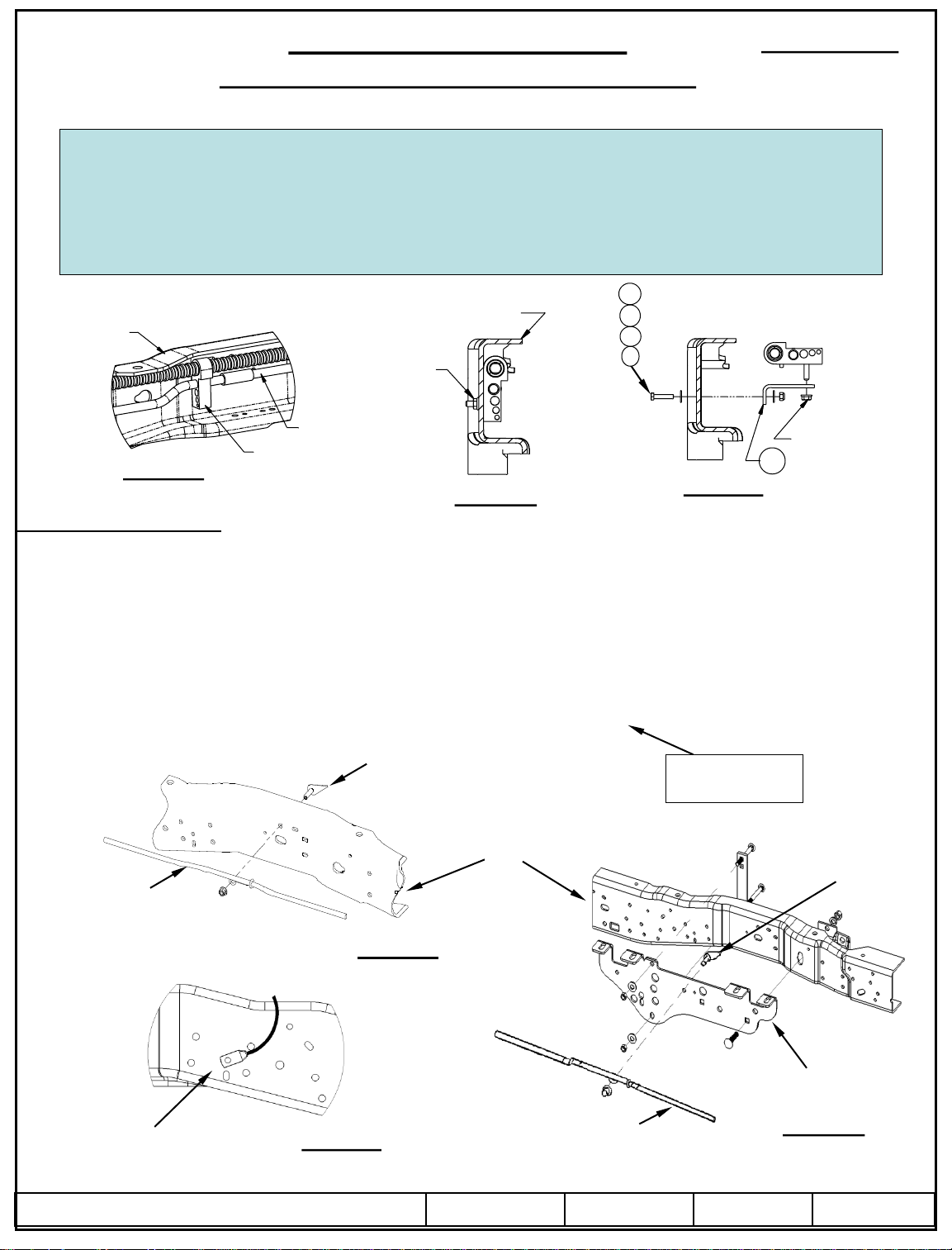
2. On 2005 to 2010 Gas Engine Vehicles Only. The vapor tube running along the inside of the driver’s side frame rail must be
relocated prior to installing the driver’s side bracket. See Figure 3a. Remove the flange nut from the outside of the frame and
keep for later use. See Figure 3b. Rotate the tubes up and out of the way. Install the L-bracket (6) with 1/4” hardware (3)(4)(5),
as shown in Figure 3c. Tighten the L-bracket (6) to the frame, but leave the tube holder loose to aid bracket installation.
3. On 1999 To 2004 Vehicles Only. Temporarily remove the emergency brake cable hangers from the frame of the truck and keep
the hardware. See Figure 4a. Also disconnect the bed safety cable and re-install in an available nearby hole once frame bracket is
installed. See Figure 4c.
Driver’s side frame
Brake line
Retain hardware
Vehicle Forward
Fig 4a,4b,4c
Driver’s side frame
Retain hardware
Figure 4a
Bed Safety Cable
©2012 Cequent Performance Products, Inc.
Figure 4c
Driver’s side frame bracket
Brake line
Sheet 2 of 5 56005N 2/16/2012 Rev. A
Figure 4b
Page 3

Installation Instructions
CUSTOM QUICK INSTALL MOUNTING KIT
Part Numbers:
56005
1999 To 2010 Ford Super Duty F-250/F-350 & 2008 To 2010 F-450
4. Place the rear mounting rail in the box of the truck. Using your tape measure, center the rail between the weld seams on the
length of the truck box floor and the proper distance from the rear edge of the truck box as illustrated in Figure 5. See page 1 for
mounting the brackets to the rails. See below for mounting the brackets to the frame.
5. Mark and center punch the holes as per the illustration in Figure 5. Move the rail out of the way and drill each position with a
1/8”drill bit. Warning: When drilling holes be aware of potential risks, such as brake lines and fuel tanks, to vehicle
components and make appropriate safe guards to protect them from damage.
6. Temporarily position the frame brackets on the outside of the frame and check that the 1/8” drilled holes align with the slots of
the frame bracket. Remove the frame bracket from the vehicle.
7. Enlarge the 1/8”drilled holes to 9/16” with the step drill. Warning: When drilling holes be aware of potential risks, such as
brake lines and fuel tanks, to vehicle components and make appropriate safe guards to protect them from damage.
8. Loosely install the frame brackets as follows:
a. For 1999 - 2004 vehicles: Use the hardware removed in Step 3 to attach the upper brake cable to the frame bracket as
shown in Figure 4b.
b. Position the frame bracket (14) as shown in Figure 1.
c. Attach the bracket to the frame of the vehicle with the 1/2” X 4-1/2” Bolts(8) 1/2” nuts(1), 1/2”conical washers(2), and
clamps(7) as shown in Figure 1. Hand tighten the nuts only.
d. For 2008 and to 2010 trucks: Use the slot in the frame that is over the axle to attach the frame bracket with the 5/8”
carriage bolt(9). Make sure to use a 5/8” spacer(10) between the bracket and frame. See Figure 1. Attach the 5/8”(9)
bolt to the inside of the frame with 1/4” x 1-1/2” x 3” spacer(11), 5/8” lock washer(12) and hex nut(13). Finger tighten
only.
e. For 1999-2007 trucks: Use the slot in the frame that is under the rear bed support to attach the frame bracket with the
5/8” carriage bolt(9). The 5/8” spacer(10) should not be used between the bracket and frame. See Figure 2. Attach the
5/8” bolt(9) to the inside of the frame with 1/4” x 1-1/2” x 3” spacer(11), lock washer(12) and hex nut(13). Finger
tighten only.
9. Reposition the mounting rail over the holes.
10. Install the 1/2” x 2” long carriage bolts with the U-shaped spacer to be located in the corrugation between the box and the rails.
Note: The U-shaped spacer will have to be installed before inserting the 1/2" carriage bolts through the mounting rail and box
floor. This insures a metal to metal contact. A U-shaped spacer is not needed for the attachment at the center of the rail. Attach
the carriage bolts on the ends of the rails with conical washers, and nuts as per the Figure 1 and tighten snug to keep the
mounting rail from moving. Attach the carriage bolt in the middle with a conical washer and nut.
11. Place the unassembled fifth wheel legs/slider/goose into the already installed mounting rail. Position the second mounting rail
with the legs/slider/goose by inserting the tabs into the mounting rail and pushing the mounting rail tight towards the other
mounting rail. Ensure that the mounting rail is centered between the weld seams on the length of the truck box floor. This will
position the mounting rail in the correct location and ensure that the fifth wheel will have a snug fit to the truck. NOTE: If more
than one hitch product will be used with the rails then both should be used at the same time to align the second rail. This will
ensure that one product does not compromise the fit of the other.
12. Repeat the previous steps for the other side of the vehicle.
13. Tighten the fasteners in the following sequence: 1) torque the mounting rails to the frame brackets, 2) torque the frame brackets
to the truck frame. Torque all 1/2" Grade 8 hardware to 110 ft-lbs (149 N*m) and the 5/8” Grade 8
hardware to 212 ft-lbs (287 N*m).
14. On 2005 to 2010 Gas Engine Vehicles Only. Use the factory flange nut that was removed in Step 2 to tighten the tube holder
onto the L-bracket (7) as shown in Figure 3c.
15. Reinstall spare tire if it was removed.
©2012 Cequent Performance Products, Inc.
Sheet 3 of 5 56005N 2/16/2012 Rev. A
Page 4

Long & Short bed
31 15/16”
©2012 Cequent Performance Products, Inc.
Figure 5
Sheet 4 of 5 56005N 2/16/2012 Rev. A
Page 5

For Installers
For corresponding REESE® Custom Quick Install Mounting Kit part numbers as well as latest revision of installation instructions please refer to
(www.REESEPROD.COM).
1. REESE® Custom quick install mounting kit for 30153 REESE ® rails kit only.
2. Do not install mounting rails over plastic bed liners. Plastic bed liners must be cut out of the way. Base rails may be installed on spray in liner. Note:
Consult installer for recommended curing time.
3. Use only CEQUENT PERFORMANCE PRODUCTS, INC. supplied bolts, nuts, and washers to install this kit. All bolts are Grade 8 hardware, unless
otherwise noted.
4. See that owner receives and fills out warranty information page.
5. Provide these instructions to owner.
Owner Responsibilities
•Refer to vehicle tow rating for correct weight capacity.
•Refer to mounting bracket rating label for correct weight capacity.
•Check mounting system bolt tightness once per year.
•Save warranty sheet and receipt for any future support.
NOTES
LIMITED LIFETIME WARRANTY
Part No:_______________________________ Date of Original Purchase:____________
Original Owner:_________________________ Original Installer:____________________
1. Limited Lifetime Warranty (“Warranty”). Cequent Performance Products, Inc. ("We" or “Us”) warrants to the original consumer purchaser only ("You")
that the product will be free from material defects in both material and workmanship, ordinary wear and tear excepted; provided that installation and use of
the product is in accordance with product instructions. There are no other warranties, express or implied, including the warranty of merchantability or
fitness for a particular purpose. This warranty is not transferable.
2. Limitations on the Warranty. This Warranty does not cover: (a) normal wear and tear; (b) damage through abuse, neglect, misuse, or as a result of any
accident or in any other manner; (c) damage from misapplication, overloading, or improper installation; (d) improper maintenance and repair; and (e)
product alteration in any manner by anyone other than Us, with the sole exception of alterations made pursuant to product instructions and in a
workmanlike manner.
3. Obligations of Purchaser. To make a Warranty claim, contact Us, at our principal address of 47912 Halyard Dr. Suite 100, Plymouth, MI 48170, 1-888-
521-0510, identify the product by model number, and follow the claim instructions that will be provided. Any returned product that is replaced by Us
becomes our property. You will be responsible for return shipping costs. Please retain your purchase receipt to verify date of purchase and that You are the
original consumer purchaser. The product and the purchase receipt must be provided to Us in order to process Your Warranty claim.
4. Remedy Limits. Product replacement is Your sole remedy under this Warranty. We shall not be liable for service or labor charges incurred in removing
or replacing a product or any incidental or consequential damages of any kind.
5. Assumption of Risk. You acknowledge and agree that any use of the product for any purpose other than the specified use(s) stated in the product
instructions is at Your own risk.
6. Governing Law. This Warranty gives You specific legal rights, and You also may have other rights which vary from state to state. This Warranty is
governed by the laws of the State of Michigan, without regard to rules pertaining to conflicts of law. The state courts located in Oakland County, Michigan
shall have exclusive jurisdiction for any disputes relating to this Warranty.
Cequent Performance Products, Inc.
47912 Halyard Dr. Suite 100
Plymouth, MI 48170
5
©2012 Cequent Performance Products, Inc.
Sheet 5 of 5 56005N 2/16/2012 Rev. A
Page 6

Instrucciones de instalación
KIT DE MONTAJE PARA INSTALACIÓN RÁPIDA A LA MEDIDA
Número de parte:
56005
PARA LARGUEROS 30153 REESE ® ÚNICAMENTE
1999 a 2010 Ford Super Duty F-250/F-350 y 2008 a 2010 F-450
ADVERTENCIA: Bajo ninguna circunstancia recomendamos superar la capacidad de remolque del vehículo recomendada por el
fabricante del vehículo de remolque.
LEA TODAS LAS INSTRUCCIONES ANTES DE EMPEZAR LA INSTALACIÓN
Los soportes de montaje de instalación rápida a la medida REESE® sólo incluyen las piezas para instalar los soportes a la
medida al bastidor.
INSTALACIÓN DE 10
PERNOS
Equipo necesario:
Kit de tornillos: 56005F
Llaves: 3/4, 7/8, 15/16, 15 mm
Figura 1
Se exhiben 2008 -
2010
15
Brocas de taladro: 1/8”, 9/16”
Otras herramientas: Perforador, cinta de
medir
8
Frente del vehículo
Todos los tornillos
Igual en ambos lados
8
7
13
12
11
1
2
1
2
9
7
13
12
11
10
14
Figura 2
Los tornillos que se indican abajo vienen con este kit, todas las otras piezas
no identificadas se suministran con número de parte 30153.
9
Se exhiben 1999 -
2007
Artículo Descripción Cantidad Artículo Descripción Cantidad
1 TUERCA HEXAGONAL, 1/2"-13 4 9
2
ARANDELA CÓNICA, 1/2”
3 ARANDELA PLANA 1/4" (Figura 3c) 2 11
4 TUERCA, NYLOK 1/4"-20 (Figura 3c) 1 12 ARANDELA DE BLOQUEO, 5/8", CHAPADA 2
5
PERNO - CABEZA HEXAGONAL, 1/4" -20 x 11/4” Gr. 2 (Fig. 3c)
6 SOPORTE EN L (Figure 3c) 1 14 SOPORTE DEL BASTIDOR LADO CONDUCTOR 1
7 ABRAZADERA FRONTAL 2 15 SOPORTE DEL BASTIDOR LADO PASAJERO 1
8
PERNO DE CARRUAJE, 1/2”-13 X 4.5” Grado 8
4 10
1 13
4
PERNO DE CARRUAJE, 5/8”-11 X 2-1/2" Gr 8
BLOQUE, 5/8” X 1-1/2” X 2-1/8"
ESPACIADOR, 1/4” x 11/2” x 3”
TUERCA HEXAGONAL, 5/8”-11 Grado 8
2
2
2
2
© 2012 Cequent Performance Products, Inc.
Hoja 1 de 5 56005N 2/16/2012 Rev. A
Page 7

KIT DE MONTAJE PARA INSTALACIÓN RÁPIDA A LA
1999 a 2010 Ford Super Duty F-250/F-350 y 2008 a 2010 F-450
No instale largueros de montaje sobre los forros plásticos de la base. Los forros plásticos de la
base deben cortarse para permitir contacto de metal a metal. Los largueros de montaje se pueden
instalar en forros aplicados con spray.
Use únicamente pernos, tuercas y arandelas suministradas para instalar este kit. Todos los pernos
y tuercas son Grado 8 a menos que se especifique lo contrario.
Estas instrucciones son pautas únicamente, la instalación real es responsabilidad del instalador y
del propietario. Siempre mida el vehículo y el remolque antes de instalar el enganche de quinta
rueda para verificar que haya espacio en la cabina y en el parachoques para permitir los giros.
Larguero del
bastidor del
lado del
conductor
Figura 3a
Interior del larguero
Instrucciones de instalación
del bastidor
Retenedor
del tubo
Instrucciones de instalación
MEDIDA
Larguero del bastidor
del lado del conductor
Tuerca
mariposa
existente
Tubo de
vapor
Figura 3b
5
3
3
4
Números de partes:
Figura 3c
6
56005
Tuerca
mariposa
existente
1. Baje y retire la llanta de repuesto si es necesario el espacio adicional para la instalación.
2. Para modelos de motor de gas 2005 a 2010 únicamente. El tubo de vapor que va a lo largo del costado interior del larguero del
bastidor del costado del conductor se debe volver a instalar antes de instalar el soporte del costado del conductor. Ver Figura 3a.
Quite la tuerca mariposa del exterior del bastidor y guarde para uso posterior. Ver Figura 3b. Rote todos los tubos hacia arriba y
afuera del camino. Instale el soporte en L (6) con piezas de 1/4” (3) (4) (5) , como se muestra en la Figura 3c. Apriete el soporte
en L (6) al bastidor, pero deje el retenedor del tubo suelto para ayudar en la instalación del soporte.
3. En vehículos 1999 a 2004 únicamente. Retire temporalmente los ganchos del cable del freno de emergencia del bastidor del
vehículo y guarde las piezas. Ver Figura 4a. También desconecte el cable de seguridad de la base y vuelva a instalar en un orificio
cercano disponible una vez que el soporte del bastidor se instale. Ver Figura 4c.
Bastidor del costado del conductor
Línea de frenos
Guarde las piezas
Bastidor del
costado del
conductor
Frente del vehículo
Fig 4a,4b,4c
Guarde las piezas
Figura 4a
Cable de seguridad de la base
© 2012 Cequent Performance Products, Inc.
Figura 4c
Soporte del bastidor
del lado del conductor
Línea de frenos
Hoja 2 de 5 56005N 2/16/2012 Rev. A
Figura 4b
Page 8

Instrucciones de instalación
Números de partes:
KIT DE MONTAJE PARA INSTALACIÓN RÁPIDA A LA MEDIDA
56005
1999 a 2010 Ford Super Duty F-250/F-350 y 2008 a 2010 F-450
4. Coloque el larguero de montaje posterior en la caja del vehículo. Usando la cinta de medir, centre el larguero entre las costuras de
soldar a lo largo del piso del vehículo y mida la distancia correcta desde el borde posterior de la caja del vehículo como se ilustra
en la Figura 5. Ver página 1 para instalar los soportes en los largueros. Ver abajo para instalar los soportes en el bastidor.
5. Marque y centre los orificios según la ilustración en la Figura 5. Mueva el larguero del camino y perfore cada posición con una
broca de 1/8". Advertencia: Al perforar los orificios tenga en cuenta los riesgos potenciales para los componentes del
vehículo como las líneas de frenos y los tanques de combustible, para los componentes del vehículo y tome las medidas
necesarias para protegerlos de daños.
6. Coloque temporalmente los soportes del bastidor en el exterior del bastidor y revise que los orificios perforados de 1/8" se alineen
con las ranuras del soporte del bastidor. Retire el soporte del bastidor del vehículo.
7. Incremente los orificios perforados de 1/8" a 9/16” con el taladro. Advertencia: Al perforar los orificios tenga en cuenta los
riesgos potenciales como las líneas de frenos y los tanques de combustible, para los componentes del vehículo y tome las
medidas necesarias para protegerlos de daños.
8. Instale sin apretar los soportes del bastidor posterior de la siguiente manera:
a. Para kit de largueros 1999-2004 Use las piezas que se quitaron en el paso 3 para instalar el cable superior del freno al
soporte del bastidor como se muestra en la Figura 4b.
b. Coloque el soporte del bastidor (14) como se muestra en la Figura 1.
c. Instale el soporte al bastidor del vehículo con los pernos de 1/2” x 4-1/2" (8), las tuercas de 1/2", las arandelas cónicas
(7) y abrazaderas como se muestra en la Figura 1. Apriete las tuercas a mano. únicamente.
d. Para vehículos 2008 a 2010: Use la ranura en el bastidor que está sobre el eje para instalar el soporte del bastidor con el
perno de carruaje de 5/8”(9). Verifique que usa un espaciador de 5/8” (10) entre el soporte y el bastidor. Ver Figura 1.
Instale el perno de 5/8” (9) en el interior del bastidor con el espaciador de 1/4” x 1-1/2” x 3” (11), arandela de bloqueo
de 5/8” (12) y tuerca hexagonal (13). Apriete a mano únicamente.
e. Para vehículos 1999-2007: Use la ranura en el bastidor que está debajo del soporte posterior de la base para instalar el
soporte del bastidor con el perno de carruaje de 5/8” (9). El espaciador de 5/8” (10) no se debe usar entre el soporte y
el bastidor. Ver Figura 2. Instale el perno de 5/8” (9) al interior del bastidor con un espaciador de 1/4” x 1-1/2” x 3”
(11), arandela de bloqueo (12) y tuerca hexagonal (13). Apriete a mano únicamente.
a. Vuelva a colocar el larguero de montaje sobre los orificios.
b. Instale los pernos de carruaje de 1/2" x 2" de largo con los espaciadores en forma de U en el corrugado entre la caja y los
largueros. Nota: El espaciador en forma de U tendrá que instalarse antes de insertar los pernos de carruaje de 1/2" a través del
larguero de montaje y el piso de la caja. Esto asegura un contacto de metal a metal. No se necesita un espaciador en U para la
instalación en el centro del larguero. Instale los pernos de carruaje en los extremos de los largueros con arandelas cónicas y
tuercas según la Figura 1 y apriete hasta ajustar para impedir que el larguero de montaje se mueva. Instale el perno de carruaje
en el centro con una arandela cónica y tuerca.
c. Coloque la 5ta rueda/monturas/deslizador/ganso sin armar dentro del larguero de montaje ya instalado. Coloque el segundo
larguero de montaje con las patas/deslizador/ganso insertando las lengüetas dentro del larguero de montaje y empujando el
larguero de montaje firmemente hacia el otro larguero de montaje. Verifique que el larguero de montaje esté centrado entre las
costuras de soldar a lo largo del piso de la caja del vehículo. Esto posicionará el larguero en la ubicación correcta y verificará
que la quinta rueda quede ajustada en el vehículo. NOTA: Si se va a usar más de un producto de enganche con los largueros
entonces se deben usar ambos al mismo tiempo para alinear el segundo larguero. Esto asegurará que un producto no
comprometa el ajuste del otro.
d. Repita los pasos anteriores para el otro lado del vehículo.
e. Apriete los tornillos en la siguiente secuencia. 1) apriete los largueros de montaje en los soportes del bastidor 2) apriete los
soportes del bastidor al bastidor del vehículo. Apriete todas las piezas de 1/2" Grado 8 a 110 pies-lbs (149 N*m)
y las piezas de 5/8” Grado 8 a 212 pies-lbs (287 N*m).
f. Para modelos de motor de gas 2005 a 2010 únicamente. Use la tuerca mariposa de fábrica que se retiró en el paso 2 para
apretar el retenedor de tubo en el soporte en L (7) como se muestra en la Figura 3c.
g. Vuelva a instalar la llanta de repuesto si se retiró.
© 2012 Cequent Performance Products, Inc.
Hoja 3 de 5 56005N 2/16/2012 Rev. A
Page 9

DIMENSIONES ESPECÍFICAS PARA KIT DE LARGUEROS 56005
LARGUEROS DE
MONTAJE
COSTURA
DE SOLDAR
Base larga y base corta
LARGUERO
DE MONTAJE
ORIFIO DE
MONTAJE
SOPORTE DEL
BASTIDOR
LÍNEA CENTRAL
ORIFICIO
PERNO BASE
VEHÍCULO
COSTURA
DE SOLDAR
(REF. ÚNICAMENTE)
31 15/16”
LARGUERO
DE MONTAJE
LÍNEA CENTRAL
ENGANCHE
APROX. 52-5/16” DESDE FRENTE DE CAJA – CAJA 8” – 0”
APROX. 36-1/8” DESDE FRENTE DE CAJA – CAJA 5” – 3/4”
SOPORTE DEL ENGANCHE/DESLIZADOR/CUELLO
(SE MUESTRA EL SOPORTE DEL ENGANCHE)
MIDA DESDE ESTA
ÁREA ÚNICAMENTE
NOTA: SE MUESTRA CON PUERTA TRASERA RETIRADA
LARGUERO
DE MONTAJE
FRENTE DEL
VEHÍCULO
© 2012 Cequent Performance Products, Inc.
SE MUESTRAN
LARGUERO DE
MONTAJE Y PIN
SOPORTE DEL
EJE
LÍNEA CENTRAL
Hoja 4 de 5 56005N 2/16/2012 Rev. A
BASTIDOR
BASTIDOR DEL
VEHÍCULO
Figura 5
Page 10

Para los instaladores
Para los números de partes correspondientes del Kit de montaje de instalación rápìda a la medida REESE® así como para la versión más reciente de las
instrucciones de instalación, consulte (www.REESEPROD.COM).
1.Kit de instalación rápida a la medida REESE ® 30153 para kit de largueros Reese ® únicamente.
2.No instale largueros de montaje sobre los forros plásticos de la base. Los forros plásticos de la base se deben recortar para despejar el camino. Los
largueros de la base se pueden instalar en forros aplicados con spray. Nota: Consulte con el instalador para las recomendaciones de tiempo de curado.
3.Use únicamente los pernos, tuercas y arandelas suministrados por CEQUENT PERFORMANCE PRODUCTS, Inc. para instalar este kit. Todos los
tornillos son grado 8. a menos que se especifique lo contrario.
4.Verifique que el propietario reciba y llene la página de información de la garantía.
5.Entregue estas instrucciones al propietario.
Responsabilidades del propietario
•Consulte la calificación del vehículo de remolque para la capacidad de peso correcto.
•Consulte la etiqueta de calificación del soporte de montaje para la capacidad de peso correcto.
•Revise la firmeza de los pernos del sistema de montaje una vez al año.
•Guarde la garantía y el recibo para cualquier referencia futura.
NOTAS
GARANTÍA LIMITADA DE POR VIDA
Número de parte:_______________________________ Fecha de compra original :____________
Propietario original :_________________________ Instalador original: ____________________
1. GARANTÍA DE POR VIDA LIMITADA (Garantía) Cequent Performance Products, Inc. ("Nosotros” o “Nuestro”) garantiza al comprador minorista
original únicamente ("usted") que el producto estará libre de defectos materiales y de mano de obra, con la excepción del uso y desgaste habitual, siempre y
cuando la instalación y el uso del producto esté de acuerdo con las instrucciones del producto. No existen otras garantías, expresas o implícitas, incluida la
garantía de comerciabilidad o idoneidad para un propósito en particular. Esta garantía no es transferible.
2. Limitaciones de la garantía. Esta garantía limitada no cubre lo siguiente: (a) desgaste normal y habitual; (b) daño por abuso, negligencia, mal uso, o
como resultado de cualquier accidente o de cualquier otra manera; (c) daño por aplicación o instalación incorrectas o sobrecarga; (d) mantenimiento y
reparación incorrectos; y (e) alteración del producto de cualquier manera por alguien que no seamos nosotros, con la única excepción de alteraciones
realizadas de acuerdo con las instrucciones del producto y de una manera profesional.
3. Obligaciones del comprador. Para hacer una reclamación de garantía, contáctenos en nuestra dirección principal en 47912 Halyard Dr. Suite 100,
Plymouth, MI 48170, 1-888-521-0510, identifique el producto por número de modelo y siga las instrucciones que se le darán para la reclamación.
Cualquier producto devuelto que se reemplace o se reembolse se convierte en propiedad nuestra. Usted será responsable por los costos de envío del
producto. Conserve el recibo de compra para verificar la fecha de compra y que usted es el comprador original. Nos debe entregar el producto y el recibo
de compra para procesar su reclamo de garantía.
4. Límites de compensación. La sustitución del producto es su único recurso bajo esta garantía. No seremos responsables por el servicio o cargos de mano
de obra en los que se incurra al quitar o reemplazar un producto o cualquier daño de cualquier tipo.
5. Riesgo asumido Usted reconoce y acepta que cualquier uso del producto para cualquier propósito diferente al uso(s) especificado(s) en las instrucciones
del producto es a su propio riesgo.
6. Ley gobernante. Esta garantía le otorga derechos legales. Usted también podría tener otros derechos que varían de estado a estado. Esta garantía está
regida por las leyes del estado de Michigan, sin importar las normas relativas a conflictos de ley. Las cortes estatales ubicadas en el condado de Oakland,
Michigan tendrán la jurisdicción exclusiva para cualquier disputa que surja con respecto a esta garantía.
Cequent Performance Products, Inc.
47912 Halyard Dr. Suite 100
Plymouth, MI 48170
10
© 2012 Cequent Performance Products, Inc.
Hoja 5 de 5 56005N 2/16/2012 Rev. A
Page 11

Instructions d'installation
NÉCESSAIRE DE MONTAGE RAPIDE SUR MESURE
Numéro de pièce :
56005
POUR TRAVERSES REESE®30153 SEULEMENT
Ford Super Duty F-250/F-350 1999 à 2010 – F-450 2008 à 2010
ATTENTION : En aucun cas nous ne recommandons de dépasser la
capacité de charge indiquée par le fabricant du véhicule de remorquage.
LIRE TOUTES LES INSTRUCTIONS AVANT L'INSTALLATION
Les supports du nécessaire de montage rapide sur mesure REESE®
ne comprennent que la visserie nécessaire à la fixation sur le cadre des supports sur mesure.
INSTALLATION À 10 BOULONS
Figure 1
2008 – 2010 illustré
8
7
1
2
13
12
11
Équipement requis :
Visserie : 56005F
Clés : 3/4, 7/8, 15/16, 15 mm
Mèches : 1/8”, 9/16”
15
Autres outils : Pointeau, ruban à mesurer
Avant du véhicule
Toute la visserie est
similaire des deux côtés
8
7
13
12
11
14
10
9
Quantité
4 9 Boulon carrosserie 5/8-11 x 2-1/2" Gr8 2
1 12
Art. Description
Rondelle frein plaquée 5/8"
Écrou hexagonal 5/8"-11 Gr8
Support de cadre côté conducteur
Support de cadre côté passager
Feuille 1 de 5 56005N 2/16/2012 Rev. A
1999 – 2007 illustré
1
2
Les fixations listées ci-dessous sont fournies avec cet ensemble, toutes
les autres fixations non identifiées sont fournies avec l'article 30153.
Art. Description
1
Écrou hex. 1/2"-13
2 Rondelle conique 1/2" 4 10 Bloc 5/8 x 1-1/2 x 2-1/8" 2
3 Rondelle plate 1/4" (Figure 3c) 2 11 Espaceur 1/4 x 1 1/2 x 3" 2
4
Écrou Nylok 1/4"-20 (Figure 3c)
5 Boulon hexagonal 1/4-20 x 1 1/4" Gr2 (Figure 3c) 1 13
6 Support en L (Figure 3c) 1 14
7 Avant de la bride 2 15
8 Boulon carrosserie 1/2-13 x 4.5" Gr8 4
©2012 Cequent Performance Products, Inc.
9
Figure 2
Quantité
2
2
1
1
Page 12

Instructions d'installation
Numéro de pièce :
NÉCESSAIRE DE MONTAGE RAPIDE SUR MESURE
56005
Ford Super Duty F-250/F-350 1999 à 2010 – F-450 2008 à 2010
N'installez pas les traverses sur la doublure de caisse en plastique. La doublure de caisse en
plastique doit être découpée pour permettre le contact métal à métal. Les traverses peuvent être
installées sur une doublure pulvérisée en place.
Utilisez seulement les boulons, les écrous et les rondelles fournis pour installer ce produit. Tous les
écrous et les boulons sont de grade 8 sauf indication contraire.
Ces instructions sont données à titre indicatif, l'installation demeure la responsabilité de l'installateur
et du propriétaire. Mesurez toujours la camionnette et la remorque avant d'installer l'attelage à
sellette pour vous assurer que le dégagement à la cabine et au pare-chocs est suffisant pour
permettre les virages.
5
Longeron côté
conducteur
Tube de vapeur
Support de tube
Figure 3a
Intérieur du longeron
Instructions d’installation
Longeron côté conducteur
Écrou à embase
existant
Figure 3b
3
3
4
Figure 3c
Écrou à embase
existant
6
1. Abaisser et enlever le pneu de secours si de l'espace supplémentaire est requis pour l'installation.
2. Sur véhicules équipés d'un moteur à gaz seulement - 2005 à 2010. Le tube de vapeur qui court sur l'intérieur du longeron côté
conducteur doit être repositionné avant de poser le support côté conducteur. Voir la Figure 3a. Ôter l'écrou à embase de l'extérieur
du cadre et le conserver pour usage ultérieur. Voir la Figure 3b. Faire pivoter les tubes vers le haut et de façon à libérer l'accès.
Poser le support en L (6) à l'aide de la visserie 1/4" (3)(4)(5), comme illustré à la Figure 3c. Serrer le support en L (6) contre le
cadre, mais laisser du jeu au porte-tube pour faciliter la pose du support.
3. Sur les modèles 1999 à 2004 seulement. Enlever temporairement les supports de câble de frein d'urgence du cadre de la
camionnette et conserver la ferronnerie. Voir la Figure 4a. Enlever aussi le câble de sécurité de la plateforme et le reposer dans un
trou libre à proximité une fois le support de cadre posé. Voir la Figure 4c.
Cadre côté conducteur
Conduite de frein
Conserver la visserie
Cadre côté
conducteur
Avant du véhicule
Fig. 4a, 4b, 4c
Conserver la visserie
Figure 4a
Câble de sécurité de la plateforme
©2012 Cequent Performance Products, Inc.
Figure 4c
Support de cadre côté conducteur
Conduite de frein
Feuille 2 de 5 56005N 2/16/2012 Rev. A
Figure 4b
Page 13

Instructions d'installation
NÉCESSAIRE DE MONTAGE RAPIDE SUR MESURE
Numéro de pièce :
56005
Ford Super Duty F-250/F-350 1999 à 2010 – F-450 2008 à 2010
4. Placer la traverse de montage arrière dans la caisse de la camionnette. À l'aide du ruban à mesurer, centrer la traverse entre les
joints de soudure sur la longueur du plancher de caisse, et déterminer la distance appropriée à partir du bord arrière de la caisse,
comme illustré à la Figure 5. Voir la page 1 pour le montage des suppports sur les traverses. Voir ci-dessous pour le montage des
suppports sur le cadre.
5. Marquer l'emplacement des trous à l'aide d'un pointeau, comme illustré à la Figure 5. Écarter la traverse et percer chaque marque
à l'aide d'une mèche 1/8 po. Avertissement : Lors du perçage, veiller à ne pas endommager des composants du véhicule
comme les conduites de frein et les réservoirs d'essence, et à prendre les mesures de protection nécessaires.
6. Placer temporairement les supports de cadre sur l'extérieur du cadre et vérifier que les trous percés de 1/8 po s'alignent sur les
fentes du support de cadre. Retirer les supports de cadre du véhicule.
7. Agrandir les trous percés de 1/8 po à 9/16 po à l'aide d'un foret étagé. Avertissement : Lors du perçage, veiller à ne pas
endommager des composants du véhicule comme les conduites de frein et les réservoirs d'essence, et à prendre les mesures
de protection nécessaires.
8. Poser sans trop serrer les supports de cadre comme suit :
a. Pour les modèles 1999 à 2004 : Utiliser la ferronnerie enlevée à l'étape 3 pour fixer le câble de frein supérieur au support
de cadre, comme illustré à la Figure 4b.
b. Placer le support de cadre (14) comme illustré à la Figure 1.
c. Fixer le support sur le cadre du véhicule à l'aide de boulons (8) 1/2 x 4-1/2, d'écrous (1) 1/2, de rondelles coniques (2) 1/2 et
de brides (7), comme illustré à la Figure 1. Serrer les écrous à la main seulement.
d. Pour camionnettes 2008 à 2010 : Utiliser la fente du cadre située au-dessus de l'essieu pour fixer le support de cadre à
l'aide d'un boulon de carrosserie 5/8 po (9). S'assurer d'utiliser un espaceur 5/8 po (10) entre le support et le cadre. Voir la
Figure 1. Poser le boulon 5/8 (9) sur l'intérieur du cadre à l'aide d'un espaceur 1/4 x 1-1/2 x 3 (11), d'une rondelle frein 5/8
(12) et d'un écrou hexagonal (13). Serrer à la main seulement.
e. Pour les modèles 1999 à 2007 : Utiliser la fente du cadre située en-dessous du support de plateforme arrière pour fixer le
support de cadre à l'aide d'un boulon de carrosserie 5/8 po (9). L'espaceur 5/8 po (10) doit être utilisé entre le support et le
cadre. Voir la Figure 2. Poser le boulon 5/8 po (9) sur l'intérieur du cadre à l'aide d'un espaceur 1/4 x 1-1/2 x 3 (11), d'une
rondelle frein (12) et d'un écrou hexagonal (13). Serrer à la main seulement.
9. Repositionner la traverse de montage au-dessus des trous.
10. Poser les boulons de carrosserie longs 1/2 x 2 avec l'espaceur en forme de U qu'il faut placer dans les ondulations entre la caisse et
les traverses. Nota : L'espaceur en forme de U devra être posé avant d'insérer les boulons de carrosserie 1/2 à travers la traverse
de montage et le plancher de caisse. On obtient ainsi le contact métal à métal nécessaire. Un espaceur en U n'est pas nécessaire
pour la fixation au centre de la traverse. Fixer les boulons de carrosserie sur les extrémités des traverses à l'aide de rondelles
coniques et d'écrous selon la Figure 1 et serrer fermement pour empêcher tout mouvement de la traverse. Fixer le boulon de
carrosserie au centre à l'aide d'une rondelle conique et d'un écrou.
11. Placer l'attelage non assemblé (pattes de sellette, curseur ou col de cygne) dans le rail déjà monté. Positionner la seconde traverse
et l'attelage (pattes de sellette, curseur ou col de cygne) en insérant les languettes dans la traverse, puis en poussant cette dernière à
fond vers l'autre traverse. S'assurer que la traverse est centrée entre les joints de soudure sur la longueur du plancher de la
camionnette. La traverse sera ainsi à la position appropriée et la sellette sera bien ajustée à la camionnette. REMARQUE : Si plus
d'un attelage doit être posé sur les traverses, alors les deux doivent être utilisés en même temps pour aligner la seconde traverse.
De cette façon, un attelage ne gênera pas l'ajustement de l'autre.
12. Répéter les étapes précédentes pour l'autre côté du véhicule.
13. Serrer les fixations selon la séquence suivante : 1) les traverses contre les supports de cadre, 2) les supports de cadre contre le
cadre de la camionnette. Serrer toute la visserie 1/2 po Grade 8 au couple de 110 lb-pi (149 N.m), et la
visserie 5/8 Grade 8 au couple de 212 lb-pi (287 N.m).
14. Sur véhicules équipés d'un moteur à gaz seulement - 2005 à 2010. Utiliser l'écrou à embase d'origine enlevé à l'étape 2 pour
fixer le support de tube sur le support en L (7), comme illustré à la Figure 3c.
15. Réinstaller le pneu de secours s’il a été enlevé.
©2012 Cequent Performance Products, Inc.
Feuille 3 de 5 56005N 2/16/2012 Rev. A
Page 14

Dimensions pour Ensemble de traverses de montage 56005
Traverses de
montage
Soudure
Plateformes longue
et courte
Trou support
de cadre
Ligne centre
camionnette
Trou boulon
plateforme
31 15/16”
Mesurer depuis
cette zone seul.
Traverse de
montage
Soudure
Référence seul.
Traverse de montage
Nota: illustré avec hayon enlevé
Traverse de
montage
Centre
attelage
Env. 52 5/8 po depuis avant camion – Caisse 8 pi
Env. 36 1/8 po depuis avant camion – Caisse 5 ¾ pi
Support/Curseur/Col-de-cygne
Support illustré
Traverse et cheville
illustrées
Avant du véhicule
©2012 Cequent Performance Products, Inc.
Centre
essieu
Feuille 4 de 5 56005N 2/16/2012 Rev. A
Support de cadre
Figure 5
Cadre camionnette
Page 15

Installateurs
Pour obtenir le numéro de pièce du nécessaire de montage rapide REESE® et la dernière version des
instructions d'installation, veuillez vous reporter à (www.REESEPROD.COM).
1. Nécessaire de montage rapide sur mesure REESE®
plastique. La doublure de caisse en plastique doit être découpée pour libérer l'accès. Les traverses peuvent être installées sur une doublure pulvérisée
en place. Nota : Consulter l'installateur pour connaître le temps de durcissement recommandé.
2. Utilisez seulement les boulons, écrous et rondelles fournis par CEQUENT PERFORMANCE PRODUCTS, INC. pour installer ce produit. Tous les
boulons sont de Grade 8, sauf indication contraire.
3. S'assurer que le propriétaire a bien reçu et rempli la page de renseignements sur la garantie.
4. Remettre ces instructions au propriétaire du véhicule.
pour traverses 30153 REESE ® seulement.
N'installez pas les traverses de montage sur la doublure de caisse en
Responsabilités du propriétaire
• Se reporter à la capacité de charge nominale du véhicule pour connaître le poids exact.
• Se reporter à l'étiquette située sur le support de montage pour connaître la capacité de charge exacte.
• Vérifier le serrage des boulons du système de montage une fois par année.
• Conserver la fiche de la garantie et la preuve d'achat en cas de besoin d'assistance.
REMARQUES
GARANTIE À VIE LIMITÉE
No pièce :__________________________________ Date de l'achat initial :_________________
Propriétaire initial :_________________________ Installateur initial :____________________
1.Garantie à vie limitée (« Garantie »). Cequent Performance Products, Inc. (« Nous ») garantit à l’acheteur initial seulement (« Vous ») que le produit sera
exempt de vices de matières et de fabrication, exception faite de l’usure normale, dans la mesure où l’installation et l’utilisation du produit sont conformes
aux instructions accompagnant celui-ci. Aucune autre garantie, expresse ou implicite, ne s’applique, y compris les garanties relatives à la qualité
marchande ou à l'adéquation à un usage particulier. Cette garantie n’est pas transférable.
2. Limites de la garantie. Cette garantie ne couvre pas : (a) l’usure normale; (b) les dommages causés par l’abus, la négligence, une mauvaise utilisation, ou
résultant de tout accident survenu de quelque manière que ce soit; (c) les dommages causés par une application inappropriée, une charge excessive ou une
installation inadéquate; (d) un entretien ou une réparation inadéquate; (e) un produit modifié de quelque manière que ce soit par quiconque d’autre que
Nous, à l’exception des modifications stipulées dans les instructions accompagnant le produit et réalisées selon les règles de l’art.
3. Obligations de l’acheteur. Pour effectuer une réclamation, communiquez avec nous à notre adresse principale, 47912 Halyard Dr. Suite 100, Plymouth,
MI 48170, 1-888-521-0510, et veuillez identifier le produit d'après le numéro de modèle et suivre les directives qui vous seront fournies. Tout produit
retourné qui est remplacé par Nous devient notre propriété. Vous serez tenu d’assumer les frais d’expédition de retour. Veuillez conserver votre reçu
d’achat afin que nous puissions en vérifier la date et confirmer que Vous êtes l'acheteur initial. Le produit et le reçu d’achat doivent Nous être fournis afin
que nous puissions traiter Votre réclamation.
4. Limites des recours. Le remplacement du produit est Votre seul recours en vertu de cette Garantie. Nous ne sommes pas responsables des frais de service
ou de main-d’oeuvre encourus pour l’enlèvement ou la réinstallation d’un produit, ni des dommages accessoires ou indirects, quels qu’ils soient.
5. Acceptation des risques. Vous reconnaissez et acceptez que toute utilisation du produit à des fins autres que celle(s) stipulée(s) dans les instructions
relatives au produit est faite à vos propres risques.
6. Loi applicable. Cette Garantie Vous confère des droits légaux spécifiques, et il se peut que Vous possédiez d’autres droits qui peuvent varier d’une
province à l’autre. Cette Garantie est régie par les lois de l’État du Michigan, abstraction faite des règles relatives aux conflits de lois. Les cours de l’État
situées dans le comté d’Oakland, Michigan, constituent les autorités judiciaires exclusives relativement à tout litige relevant de cette Garantie.
©2012 Cequent Performance Products, Inc.
Cequent Performance Products, Inc.
47912 Halyard Dr. Suite 100
Plymouth, MI 48170
Feuille 5 de 5 56005N 2/16/2012 Rev. A
15
 Loading...