

Page 1
INSTALLATION INSTRUCTIONS
Product No.
MULTI-FIT PICK-UP
You can take it with you.
PLYMOUTH, MICH.
WARNING: DO NOT LUBRICATE THREADS, BOLT FAILURE MAY
OCCUR DUE TO OVER TIGHTENING.
WARNING: DO NOT DRILL OR WELD TO THIS HITCH.
FRAME
1/2” LOCK WASHER
1/2” NUT
RIVET IN FRAME
37034
SMALL PARTS
PACKAGE 37424
USE ONLY REESE SUPPLIED OR APPROVED BOLTS, LOCKNUTS,
AND WASHERS TO INSTALL THIS HITCH
5/8” BOLT
1/4 BOLT PLATE
3/8” SPACER
5/8” LOCK WASHER
5/8” NUT
IMPORTANT NOTES
TOOLS REQUIRED
5/8” DRILL BIT
15/16” SOCKET
15/16” WRENCH
3/4” SOCKET
3/4” WRENCH
2 CLAMPS
TORQUE WRENCH
1/2” BOLT
3/8” SPACER
FRONT
REAR
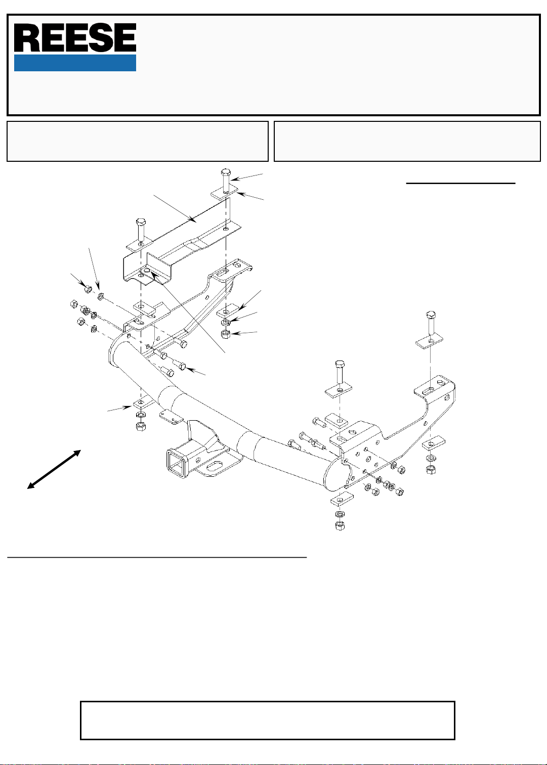
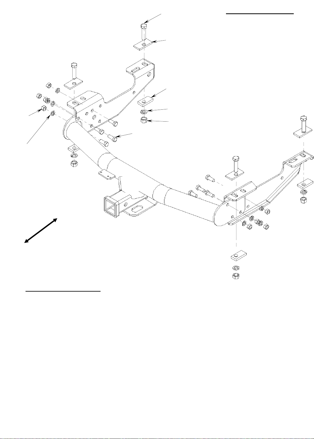
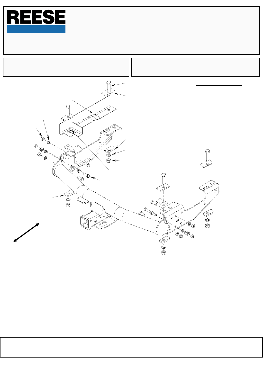
1973-1996 Ford Full Size Pickup & 1997 F-250 Heavy Duty / F-350 Heavy Duty:
1. Assemble the three pieces of the hitch together on the floor before attaching it to the truck. Using 1/2” bolts, lock washers and nuts, bolt the
brackets to the center section as shown. Place the brackets on the outside of the center section. Bolt through the holes shown in the
illustration. Leave the bolts loose enough to center brackets on truck frame. NOTE: Be sure to use four holes to bolt each bracket to the center
section.
2. Clamp the hitch to the frame with a 3/8” thick spacer between the hitch and the frame at the rear. Align the ends of the brackets with the end
of the frame as shown.
3. Using the holes in the bracket as a guide, drill 5/8” diameter holes into the frame at the locations shown.
4. Insert 5/8” bolts with bolt plates down through the frame and into the bracket. Place a 3/8” thick spacer between the frame and the bracket at
the rear mounting hole. Install a 3/8" thick spacer, lock washer and nut on each bolt.
5. Tighten the nuts in the following order: First torque the 1/2" nuts to 70 ft•lb. Then torque the 5/8" nuts to 115 ft•lb.
NOTE: SIDE BRACKETS WILL DEFLECT WHEN TIGHTENED
For Installation Assistance or Technical Help, See our Web Site at
www.reeseprod.com or call 1-800-428-7303
37034IN 9-5-07 rev_H PCN9924 © 2007 Cequent Towing Products Printed in Mexico
Page 2
TOOLS REQUIRED
15/16” SOCKET
15/16” WRENCH
3/4” SOCKET
3/4” WRENCH
5/8" DRILL BIT
TORQUE WRENCH
1/2” NUT
1/2” LOCK WASHER
3/8” SPACER
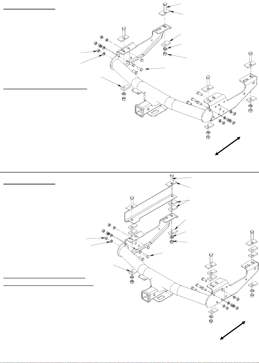
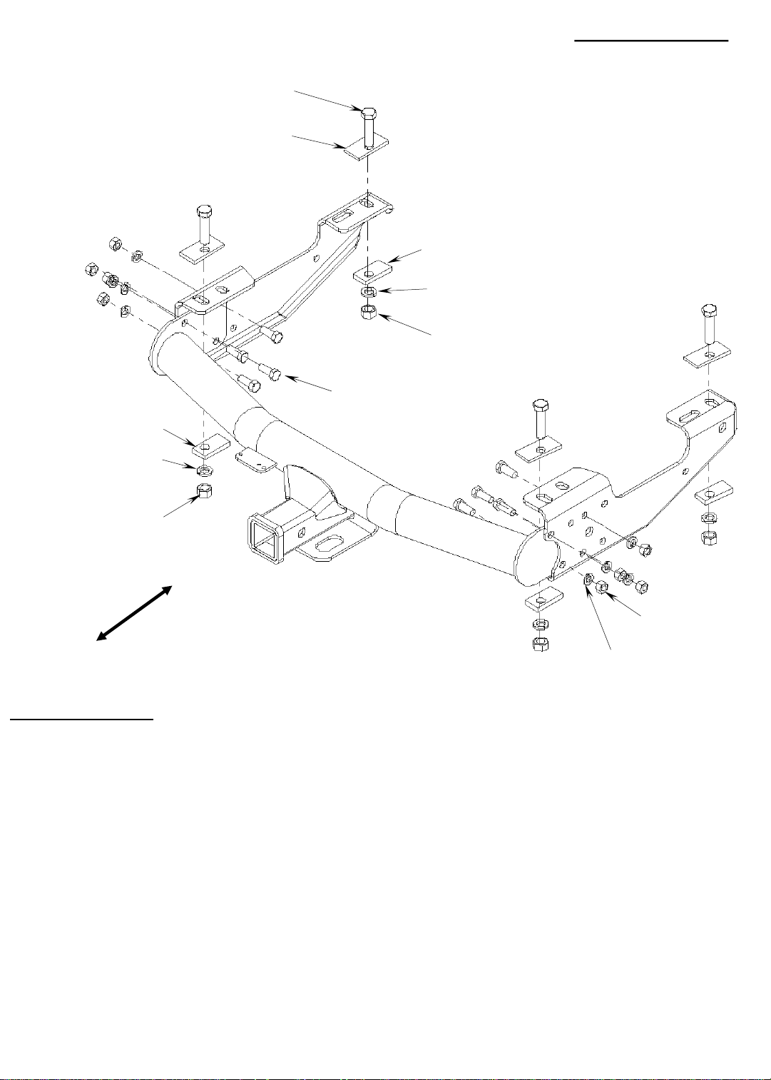
1998-2004 FORD F-250 & F-350 SUPER DUTY:
1. Align the bracket with the rear edge of the frame. Attach the
brackets to the frame as shown with 5/8” bolts and bolt plates
down through rear holes in the frame. Install 3/8" thick spacers,
5/8" lock washers, and nuts on these bolts. Leave the nuts loose
at this time.
2. Install the center section of the hitch as shown with the frame
brackets on the outside of the center section. Bolt through the
holes shown. Use the 1/2” bolts with lock washers and nuts.
NOTE: Be sure to use four holes to bolt the brackets to the
center section. Tighten enough for the brackets to make full
contact with the center section.
3. With the 5/8” drill, drill the two forward holes. Install fasteners as
shown. Install 3/8” thick spacers, 5/8” lock washers and nuts on
the bolts. Leave the nuts loose at this time.
4. Tighten the nuts in the following order: First torque the 1/2" nuts
to 70 ft•lb. Then torque the 5/8" nuts to 115 ft•lb.
5/8” BOLT
1/4” BOLT PLATE
3/8” SPACER
5/8” LOCK WASHER
5/8” NUT
1/2” BOLT
FRONT
REAR
TOOLS REQUIRED
15/16” SOCKET
15/16” WRENCH
3/4” SOCKET
3/4” WRENCH
TORQUE WRENCH
1/2” NUT
1/2” LOCK WASHER
3/8” SPACER
1997-2003 FORD F-150 & LIGHT DUTY F-250:
2004 FORD F-150 HERITAGE (OLD BODY STYLE)
1. Align the bracket with the rear edge of the frame. Place 3/8" thick
spacers between the bracket and the frame as shown. Attach
brackets to the frame as shown with 5/8” bolts and bolt plates down
through the frame, spacers, and bracket. Bolt into the first and last
holes in the bracket. Install 3/8” thick spacer with 5/8” lock washer
and nut on the each bolt. Leave the nuts loose at this time.
2. Install the center section of the hitch as shown with the frame
brackets on the inside of the center section. Use the 1/2” bolts with
lock washers and nuts. NOTE: Be sure to use four holes to bolt
each bracket to the center section.
3. Tighten the nuts in the following order:
First torque the 1/2" nuts to 70 ft•lb.
Then torque the 5/8" nuts to 115 ft•lb.
5/8” BOLT
1/4” BOLT PLATE
3/8” SPACER
3/8” SPACER
5/8” LOCK WASHER
5/8” NUT
1/2” BOLT
FRONT
REAR
Page 3
5/8” BOLT
1/4” BOLT PLATE
5/8” BOLT
3/8” SPACER
1/4” BOLT PLATE
3/8” SPACER
3/8” SPACER
TOOLS REQUIRED
15/16” SOCKET
15/16” WRENCH
3/4” SOCKET
3/4” WRENCH
19MM WRENCH
19MM SOCKET
15MM SOCKET
15MM WRENCH
5/8” DRILL
TORQUE WRENCH
1/2” BOLT
5/8” LOCK WASHER
5/8” NUT
Hole
3
Hole 2
Hole 4
FRONT
Hole 1
1/2” NUT
REAR
1/2” LOCK WASHER
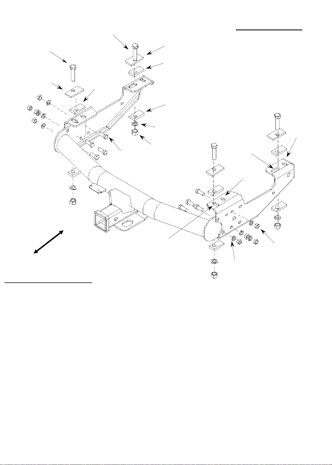
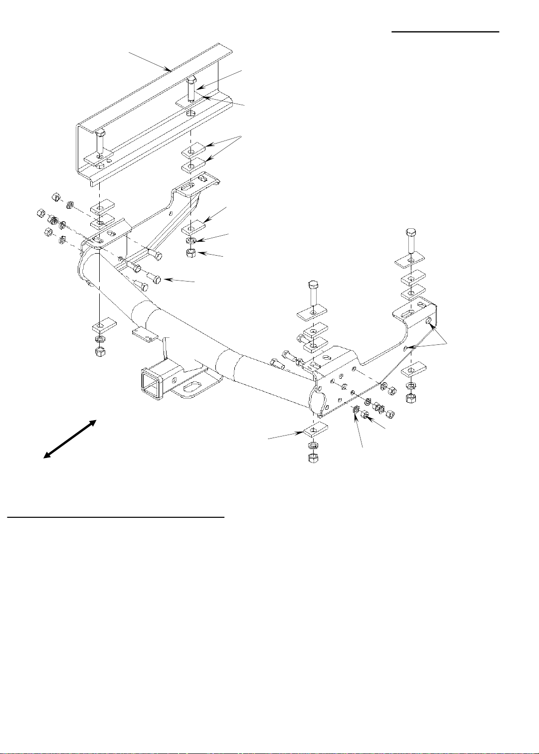
1988-2000 CHEVY & GMC (CLASSIC):
1. The 12mm diameter bolts and weld nuts at the end of the frame must be removed. ( Wear Eye Protection) Method 1) Back out the
12mm diameter bolt halfway. Drive the bolt upward by striking the bolt head with a ball peen hammer to break the nut loose. Ream out the
bolt hole to 5/8” diameter. Method 2) Remove the 12mm bolt and discard. Using a 5/8” drill bit, drill out the nut. Then remove the remainder
with a hammer and chisel. Some vehicles have an additional 8mm diameter bolt on the passenger’s side. Remove the bolt and reinstall it with
the head on the bottom of the frame.
2. If your vehicle has rivets on the bottom of the frame or the 8mm bolt, you will need to install one 3/8” thick spacer between the frame and the
bracket at each bolting location. These are needed for clearance between the bracket and the rivet head or 8mm bolt. The bracket can not be
bolted directly against the rivets or 8mmbolt.
3. Using the supplied hardware, insert 5/8” diameter bolt with bolt plate down through the hole created from the removal of the 12mm nut. Fasten
the bracket to the frame. See the illustration. For short bed use hole 2. On long bed use hole 1. NOTE: SOME DUAL PIPE EXHAUST
SYSTEMS WILL HIT THE BRACKET. THE EXHAUST WILL NEED TO BE MODIFIED. Attach with 3/8” spacer, 5/8” lock washer, and 5/8’nut.
4. (Short Beds): Insert 5/8” bolts with bolt plates down through the 1” diameter holes in the frame and into holes (4) in the brackets. Install a 3/8”
thick spacer, 5/8” lock washer, and nut on each bolt. Leave the nuts loose at this time.
5. (Long Beds): Insert 5/8” bolts with bolt plates down through the 1” diameter holes in the frame and into holes (3) in the brackets. If the forward
holes are only 1/2" diameter, use the 5/8" drill bit to enlarge them. Install a 3/8” thick spacer, 5/8” lock washer and nut on each bolt. Leave the
nuts loose at this time.
6. Place the center section between the brackets as shown. The spare tire may need to be loosened. Bolt through the center section and the
bracket with 1/2” bolts, lock washers and nuts. NOTE: Be sure to use four holes to bolt the brackets to the center section.
7. Tighten the nuts in the following order:
First torque the 1/2" nuts to 70 ft•lb.
Then torque the 5/8" nuts to 115 ft•lb.
8. Retighten the spare tire if it was loosened.
9. Be sure that the spare tire is not rubbing against the brake hose. If needed, bend the bracket that the hose mounts to a little so that you have
clearance between the tire and the brake hose.
Page 4
TOOLS REQUIRED
15/16” SOCKET
15/16” WRENCH
3/4” SOCKET
3/4” WRENCH
21MM SOCKET
TORQUE WRENCH
1/2” NUT
1/2” LOCK WASHER
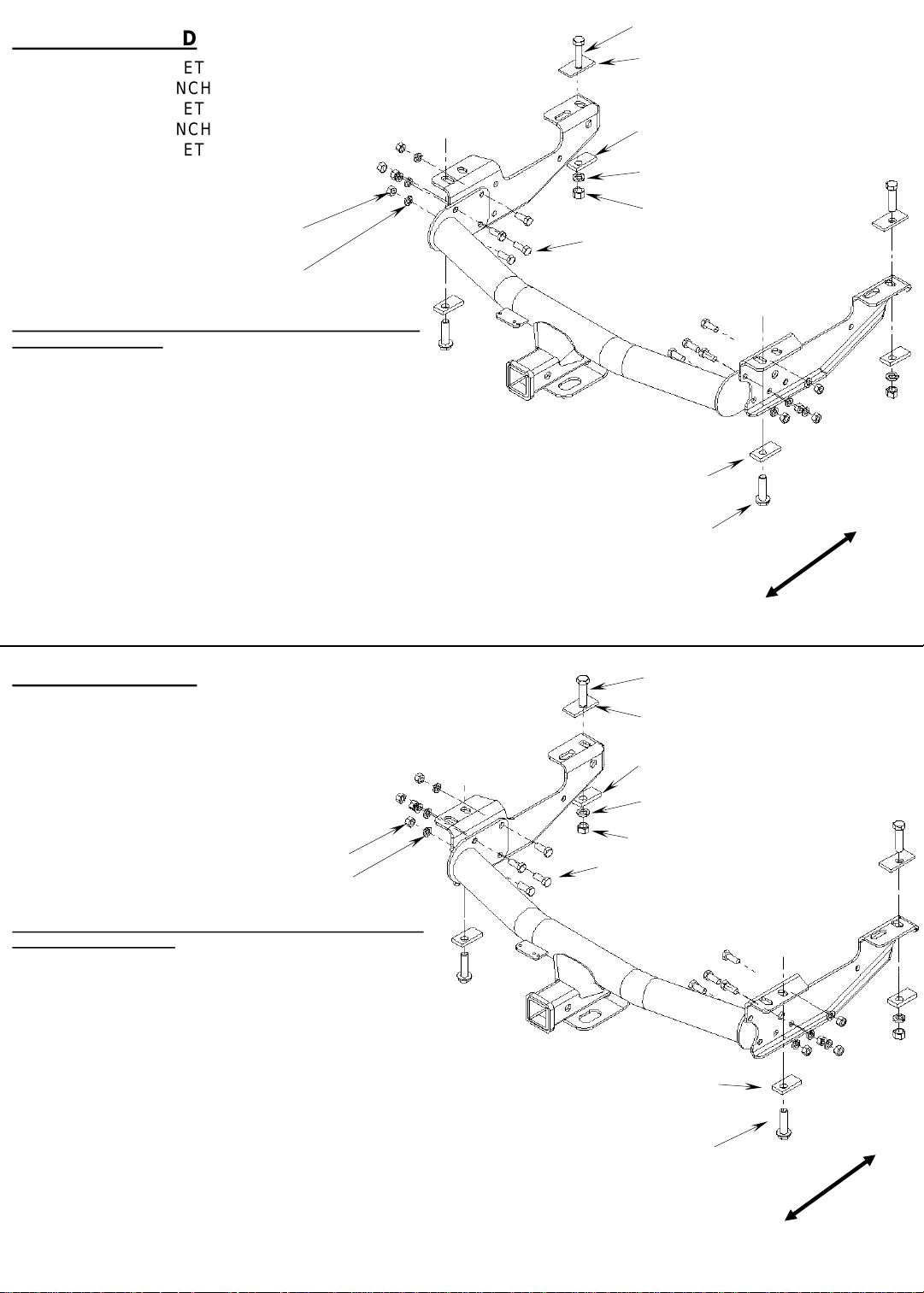
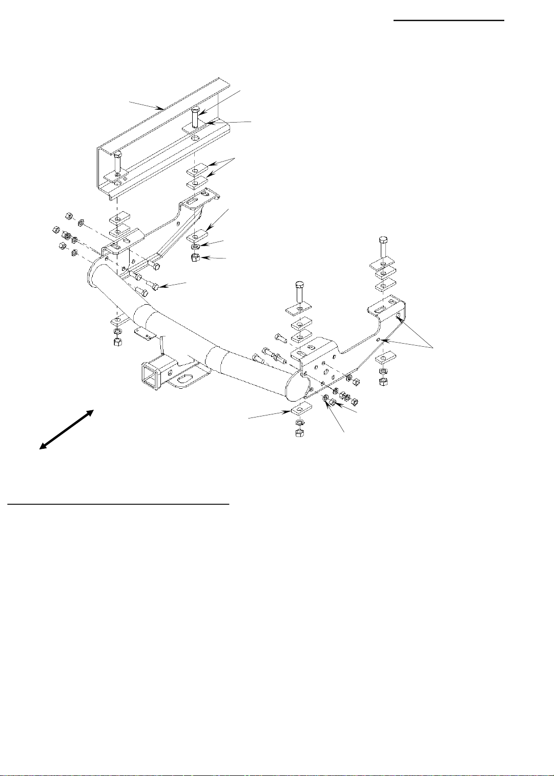
1999-2007 1500,1999-2004 2500LD CHEVY SILVERADO & GMC
SIERRA (LONG BEDS):
1. Remove the 14mm bolt from the bottom of the frame with a
21mm socket.
2. Bolt the brackets on with the 14mm bolt that was just removed
and a 3/8” thick spacer into the hole shown. Insert a 5/8” bolt
with a 1/4" bolt plate through the large hole in the frame and
into the bracket as shown. Install 3/8” thick spacers, 5/8” lock
washers and nuts on the bolts. Leave the bolts loose.
3. Install the center section between the brackets as shown. Use
the bolting location indicated. Install 1/2” bolts through the
center section and the bracket as shown. Install 1/2” lock
washers and nuts on the bolts. NOTE: Be sure to use four
holes to bolt the brackets to the center section.
4. Tighten the nuts in the following order:
First torque the 1/2" nuts to 70 ft•lb.
Then torque the5/8" nuts to 115 ft•lb, and the 14mm bolts to 85 ft-lb.
5/8” BOLT
1/4” BOLT PLATE
3/8” SPACER
5/8” LOCK WASHER
5/8” NUT
1/2” BOLT
3/8” SPACER
EXISTING FACTORY
FLANGE BOLT
FRONT
REAR
TOOLS REQUIRED
15/16” SOCKET
15/16” WRENCH
3/4” SOCKET
3/4” WRENCH
21MM SOCKET
TORQUE WRENCH
1/2” NUT
1/2” LOCK WASHER
1999-2007 1500, 1999-2004 2500LD CHEVY SILVERADO & GMC
SIERRA (SHORT BEDS):
1. Remove the 14mm bolt from the bottom of the frame with a
21mm socket.
2. Bolt the brackets on with the 14mm bolt that was just removed
and a 3/8” thick spacer into the hole shown. Insert a 5/8” bolt
with a 1/4" bolt plate through the large hole in the frame and into
the bracket as shown. Install 3/8” thick spacers, 5/8” lock
washers and nuts on the bolts. Leave the bolts loose.
3. Install the center section between the brackets as shown. Use
the bolting location indicated. Install 1/2" bolts through the
center section and the bracket as shown. Install 1/2” lock
washers and nuts on the bolts. NOTE: Be sure to use four holes
to bolt the brackets to the center section.
5/8” BOLT
1/4” BOLT PLATE
3/8” SPACER
5/8” LOCK WASHER
5/8” NUT
1/2” BOLT
3/8” SPACER
EXISTING FACTORY
14MM FLANGE BOLT
FRONT
4. Tighten the nuts in the following order:
First torque the 1/2" nuts to 70 ft•lb.
Then torque the5/8" nuts to 115 ft•lb, and the 14mm bolts to 85 ft-lb.
REAR
Page 5
1/2” NUT
1/2” LOCK WASHER
1/2” BOLT
5/8” BOLT
1/4” BOLT PLATE
3/8” SPACER
5/8” LOCK WASHER
5/8” NUT
TOOLS REQUIRED
15/16” SOCKET
15/16” WRENCH
3/4” SOCKET
3/4” WRENCH
21MM SOCKET
TORQUE WRENCH
SAFETY GLASSES
FRONT
REAR
2000-2006 TOYOTA TUNDRA :
1. Ream existing hole at the rear of the frame to except a 5/8” bolt and install the 5/8” bolts through the bolt plates and into
the frame. With the 3/8” spacer, 5/8” lock washer, and 5/8” nut bolt the brackets to the frame. Leave the bolts loose
enough to center bracket on frame of truck. Do not install fasteners in the forward hole in the brackets at this time.
2. Install the center section to the brackets as shown. Use the bolting location indicated. Install 1/2” bolts through the center
section and the bracket as shown. Install 1/2” lock washers and nuts on the bolts.
3. Using the forward most holes in the brackets as a guide drill a 5/8” hole and install the 5/8” bolts with 1/4” bolt plates
through the frame and brackets. Then install the 3/8” spacer, 5/8” lock washer, and 5/8” nuts.
NOTE: Be sure to use four holes to bolt the brackets to the center section.
4. Tighten the nuts in the following order:
First torque the 1/2" nuts to 70 ft•lb.
Then torque the 5/8" nuts to 115 ft•lb.
NOTE: SIDE BRACKETS MAY DEFLECT WHEN TIGHTENED
Page 6
3/8” SPACER
5/8” BOLT
1/4” BOLT PLATE
TOOLS REQUIRED
15/16” SOCKET
15/16” WRENCH
3/4” SOCKET
3/4” WRENCH
5/8" DRILL BIT
TORQUE WRENCH
3/8” SPACER
5/8” LOCK WASHER
5/8” NUT
1/2” BOLT
5/8” LOCK WASHER
5/8” NUT
FRONT
1/2” NUT
REAR
1971-1993 Dodge Pick Up:
1. Insert a 5/8” bolt with a 1/4” bolt plate down through the 1” diameter hole at the end of the frame. Do this on both sides. Fasten the frame
brackets as shown, to the frame with 3/8" thick spacers, lock washers and nuts. Leave the bolts loose enough to center bracket on frame of
truck.
2. Install the center section between the brackets as shown. Bolt through the center section and the brackets with 1/2” bolts, lock washers and
nuts. Use the holes shown. Leave the nuts finger tight at this time. Some spare tire carriers may need to be modified if the hitch hits the
carrier. NOTE: Be sure to use four holes to bolt the brackets to the center section.
3. Using the hole in the bracket as a guide, drill a 5/8” diameter hole through the frame. Use the farthest front hole. Do this on both sides.
4. Insert 5/8” bolts with 1/4” bolt plates down through the frame and the bracket. Install 3/8” thick spacers, 5/8” lock washers and nuts on the
bolts.
5. Tighten the nuts in the following order:
First torque the 1/2" nuts to 70 ft•lb.
Then torque the 5/8" nuts to 115 ft•lb.
1/2” LOCK WASHER
NOTE: SIDE BRACKETS WILL DEFLECT WHEN TIGHTENED
Page 7
FRAME
3/8” SPACER
5/8” LOCK WASHER
5/8” NUT
1/2” BOLT
5/8” BOLT
1/4” BOLT PLATE
3/8” SPACER
TOOLS REQUIRED
5/8” DRILL BIT
3/8” DRILL BIT
15/16” SOCKET
15/16” WRENCH
3/4” SOCKET
3/4” WRENCH
13MM SOCKET
9/16” SOCKET
9/16” WRENCH
TORQUE WRENCH
RE-ATTATCH
EXHAUST
HANGER IN ONE
OF THESE HOLES
FRONT
3/8” SPACER
1/2” NUT
1/2” LOCK WASHER
REAR
1994-2001 and 2002 2500/3500 Dodge Pick Up Short Bed:
1. The spare tire may need to be loosened for installation.
2. Bolt the brackets to the frame as shown with a 5/8” bolt and 1/4” bolt plate inserted through the 1” diameter hole in the end of the frame. Install
two 3/8” thick spacers between the frame and brackets at the rear bolting locations. Install 3/8" thick spacers, lock washers and nuts on the
bolts. NOTE: For some models, the exhaust hanger will need to be unbolted from the frame.
3. Install the center section between the brackets as shown. Use the hole pattern that works best for your truck. Insert 1/2" bolts through the
center section and the brackets. Install 1/2” lock washers and nuts on the bolts. Finger tighten the bolts at this time. NOTE: Be sure to use four
holes to bolt each bracket to the center section.
4. Using the hole in the bracket as a guide, drill a 5/8" hole through the frame. Use the hole shown in the diagram. Install 5/8” bolts with bolt
plates into the holes. Be sure to insert two 3/8” thick spacers between the frame and the brackets. Install 3/8” thick spacers, lock washers and
nuts on the bolts.
5. If the exhaust hanger was removed, drill a 3/8” hole through the hanger and attach it to the hitch bracket in one of the holes indicated. Use the
3/8" hardware provided to re-attach the exhaust hanger.
6. Tighten the nuts in the following order:
First torque the 1/2" nuts to 70 ft•lb.
Then torque the 5/8" nuts to 115 ft•lb.
7. If the spare tire was loosened, retighten it now.
Page 8
FRAME
1/2” BOLT
5/8” BOLT
1/4” BOLT PLATE
3/8” SPACER
3/8” SPACER
5/8” LOCK WASHER
5/8” NUT
TOOLS REQUIRED
3/8” DRILL BIT
15/16” SOCKET
15/16” WRENCH
3/4” SOCKET
3/4” WRENCH
13MM SOCKET
9/16” SOCKET
9/16” WRENCH
TORQUE WRENCH
RE-ATTATCH EXHAUST
HANGER IN ONE OF
THESE HOLES
FRONT
3/8" SPACER
1/2” NUT
1/2” LOCK WASHER
REAR
1994-2001 and 2002 2500/3500 Dodge Pick Up Long Bed:
1. The spare tire may need to be loosened for installation.
2. Bolt the brackets to the frame as shown with a 5/8” bolt and 1/4” bolt plate inserted through the 1” diameter hole in the end of the frame. Install
two 3/8” thick spacers between the frame and brackets at the rear bolting locations. Install 3/8" thick spacers, lock washers and nuts on the
bolts. NOTE: For some models, the exhaust hanger will need to be unbolted from the frame.
3. Install the center section between the brackets as shown. Use the hole pattern that works best for your truck. Insert 1/2” bolts through the
center section and the brackets. Install 1/2” lock washers and nuts on the bolts. Finger tighten the bolts at this time. NOTE: Be sure to use four
holes to bolt each bracket to the center section.
4. Insert a 5/8” bolt with a 1/4" bolt plate through the 1” hole in the frame and into the bracket as shown. Insert two 3/8” thick spacers between
the frame and the bracket. Install a 3/8” thick spacer, 5/8” lock washer and nut on the bolt. Do this on both sides.
5. If the exhaust hanger was removed, drill a 3/8” hole through the hanger and attach it to the hitch bracket in one of the holes indicated. Use the
3/8" hardware provided to re-attach the exhaust hanger.
6. Tighten the nuts in the following order:
First torque the 1/2" nuts to 70 ft•lb.
Then torque the 5/8" nuts to 115 ft•lb.
7. If the spare tire was loosened, retighten it now.
Page 9
Vous pouvez tout apporter.
PLYMOUTH, MICH.
INSTRUCTIONS D’INSTALLATION
ATTELAGE POLYVALENT
POUR CAMIONNETTES
NO DE PRODUIT
37034
PAQUET DE
PETITES PIÈCES 37424
AVERTISSEMENT: Ne lubrifiez pas les filets; serrer excessivement les
boulons pourrait les endommager ou les briser.
AVERTISSEMENT: Ne percez ni soudez cet attelage.
CADRE
RONDELLE DE
BLOCAGE DE 1/2”
ÉCROU DE 1/2”
RIVET AU CADRE
BOULON DE 1/2”
CALE DE 3/8”
Utilisez seulement les boulons, les écrous et les rondelles fournis ou
approuvés par Reese pour installer cet attelage.
BOULON DE 5/8”
PLAQUE DE BOULON
DE 1/4"
NOTES IMPORTANTES
OUTILS REQUIS
5/8" FORET
15/16" DOUILLE
15/16" CLÉ
3/4" DOUILLE
3/4" CLÉ
SERRE-JOINTS (2)
CLÉ DYNAMOMÉTRIQUE
CALE DE 3/8”
RONDELLE DE BLOCAGE DE 5/8”
ÉCROU DE 5/8”
AVANT
ARRIÈRE
1973-1996 Ford Camionnette de plein grandeur et 1997 F-250 Heavy Duty / F-350 Heavy Duty:
1. Assemblez les trois pièces de l'attelage au sol avant de l'attacher à la camionnette. Utilisez les boulons striés, les rondelles de blocage, et
les écrous de 1/2" pour boulonner les supports à la section centrale comme illustré. Mettez les supports à l'extérieur de la section centrale.
Mettez les boulons à travers les trous comme montré au diagramme. Gardez les boulons assez desserrés pour pouvoir centrer les supports
par rapport au cadre du véhicule. NOTE : soyez certain d'utiliser trois trous pour boulonner chaque support à la section centrale.
2. Serrez l'attelage au cadre avec une cale de 3/8" d'épaisseur entre l'attelage et le cadre à l'arrière. Alignez les extrémités des supports avec
l'extrémité du cadre comme montré.
3. Utilisez les trous des supports comme guide pour percer des trous de 5/8" de diamètre dans le cadre aux points montrés.
4. Insérez les boulons de 5/8" avec les plaques de boulon vers le bas à travers le cadre et le support. Mettez une cale de 3/8" d'épaisseur
entre le cadre et le support au trou de montage arrière. Installez les cales de 3/8" d'épaisseur, les rondelles de blocage, et les écrous aux
boulons.
5. Serrez les écrous dans l’ordre suivant : d’abord les écrous de 1/2" au couple de 70 pi•lb, puis les écrous de 5/8" au couple de 115 pi•lb.
REMARQUE : LES SUPPORTS LATÉRAUX FLÉCHISSENT AU SERRAGE
Si une assistance ou aide technique est nécessaire pour une installation,
composez le www.reeseprod.com ou appel 1-800-428-7303
37034IN 9-5-07 rev_H PCN9924 © 2007 Cequent Towing Products - Imprimé au Mexique
Page 10

OUTILS REQUIS
15/16” DOUILLE
15/16” CLÉ
3/4” DOUILLE
3/4” CLÉ
5/8" FORET
CLÉ DYNAMOMÉTRIQUE
BOULON DE 5/8”
PLAQUE DE BOULON DE 1/4”
CALE DE 3/8”
RONDELLE DE BLOCAGE DE 5/8”
ÉCROU DE 1/2”
RONDELLE DE BLOCAGE DE 1/2”
CALE DE 3/8”
1998-2004 FORD F-250 & F-350 SUPER DUTY:
1. Alignez le support avec le rebord arrière du cadre. Attachez les
supports au cadre comme montré, en insérant les boulons de 5/8"
avec les plaques de boulons vers le bas à travers les trous arrière du
cadre. Installez les cales de 3/8" d'épaisseur, les rondelles de
blocage de 5/8", et les écrous. Ne serrez pas encore les écrous.
2. Installez la section central de l'attelage comme montré, les supports à l'extérieur de la section centrale.
Boulonnez à travers les trous indiqués. Utilisez les boulons de 1/2" avec les rondelles de blocage et les
écrous. NOTE : utilisez quatre trous pour boulonner chaque support à la section centrale. Serrez les écrous
assez pour que les supports fassent un bon contact avec la section centrale.
3. Utilisez le foret de 5/8" pour percer les deux trous de devant. Installez les boulons de 5/8" avec les plaques
de boulon comme montré. Installez les cales de 3/8" d'épaisseur, les rondelles de blocage et les écrous de
5/8" aux boulons.
4. Serrez les écrous dans l'ordre suivant : Premièrement serrez les écrous de 1/2" au couple de 70 pi•lb.
Ensuite, serrez les écrous de 5/8" au couple de 115 pi•lb.
BOULON DE 1/2”
OUTILS REQUIS
15/16” DOUILLE
15/16” CLÉ
3/4” DOUILLE
3/4” CLÉ
CLÉ DYNAMOMÉTRIQUE
ÉCROU DE 5/8”
AVANT
ARRIÈRE
BOULON DE 5/8”
PLAQUE DE BOULON DE 1/4”
CALE DE 3/8”
CALE DE 3/8”
ÉCROU DE 1/2”
RONDELLE DE BLOCAGE DE 1/2”
BOULON DE 1/2”
CALE DE 3/8”
1997-2003 FORD F-150 et F-250 LÉGER:
HÉRITAGE 2004 DE FORD F-150 (VIEILLE CARROSSERIE)
1. Alignez le support avec le rebord arrière du cadre. Mettez les cales
de 3/8" d'épaisseur entre le support et le cadre comme montré.
Attachez les supports au cadre comme montré au moyen des
boulons de 5/8" et les plaques de boulon installés vers le bas à
travers le cadre, les cales, et les supports. Installez les boulons
dans les premiers et les derniers trous des supports. Installez les
cales de 3/8" d'épaisseur avec les rondelles de blocage de 5/8" et
les écrous aux boulons. Ne serrez pas encore les écrous.
2. Installez la section central de l'attelage comme montré, les supports à l'intérieur de la section centrale.
Utilisez les boulons de 1/2" avec les rondelles de blocage et les écrous. NOTE : utilisez quatre trous pour
boulonner chaque support à la section centrale.
3. Serrez les écrous dans l'ordre suivant : Premièrement serrez les écrous de 1/2" au couple de 70 pi•lb.
Ensuite, serrez les écrous de 5/8" au couple de 115 pi•lb.
RONDELLE DE BLOCAGE
DE 5/8 ”
ÉCROU DE 5/8”
AVANT
ARRIÈRE
Page 11

BOULON DE 5/8"
PLAQUETTE DE
BOULON 1/4"
BOULON DE 5/8"
ENTRETOISE
DE 3/8"
PLAQUETTE DE
BOULON 1/4"
ENTRETOISE
DE 3/8"
ENTRETOISE
DE 3/8"
RONDELLE DE
BLOCAGE DE 5/8"
OUTILS REQUIS
DOUILLE 15/16"
CLÉ 15/16"
DOUILLE 3/4"
CLÉ 3/4"
CLÉ 19 mm
DOUILLE 19 mm
DOUILLE 15 mm
CLÉ 15 mm
PERCEUSE 5/8"
CLÉ DYNOMOMÉTRIQUE
Trou 4
ÉCROU DE 5/8"
BOULON DE 1/2"
Trou 3
Trou 2
AVANT
Trou 1
ARRIÈRE
CHEVROLET ET GMC (CLASSIC) (1988-2000) :
1. Vous devez retirer les boulons de 12 mm et les boulons soudés à l'extrémité du cadre (portez des lunettes de protection). 1ère méthode :
retirez à moitié le boulon de 12 mm. Faites monter le boulon en tappant dessus avec un marteau à panne ronde, de manière à décoller
l’écrou. Élargissez le trou du boulon à 5/8" de diamètre. 2ème méthode : retirez le boulon de 12 mm et jetez-le. Percez l’écrou à l’aide d’un
foret de 5/8". Retirez ensuite la partie restante avec un marteau et un burin. Certains véhicules sont équipés d’un boulon supplémentaire de 8
mm du côté passager. Ôtez le boulon et replacez-le, la tête au bas du cadre.
2. Si votre véhicule est équipé de rivets ou d’un boulon de 8 mm dans le bas du cadre, vous devrez insérer une entretoise de 3/8" entre le cadre
et le support, à chaque point de boulonnage. Elles permettent de créer un espace entre le support et la tête du rivet ou du boulon de 8 mm.
Vous ne devez pas boulonner le support directement contre les rivets ou contre le boulon de 8 mm.
3. À l’aide de la quincaillerie fournie, insérez un boulon de de 5/8" de diamètre avec plaquette dans le trou formé par le retrait de l’écrou de
12 mm. Fixez le support sur le cadre (voir illustration). Sur les caisses courtes, utilisez le trou 2. Sur les caisses longues, utilisez le trou 1.
NOTE : CERTAINS SYSTÈMES À ÉCHAPPEMENT DOUBLE PEUVENT COINCER LE SUPPORT. VOUS DEVEZ ALORS MODIFIER
L’ÉCHAPPEMENT. Fixez le support avec une entretoise de 3/8", une rondelle de blocage de 5/8" et un écrou de 5/8".
4. (Caisses courtes) : insérez les boulons de 5/8" avec les plaques de boulons vers le bas à travers les trous de 1" de diamètre dans le cadre, et
dans les trous (4) au support. Installez une cale de 3/8" d'épaisseur, une rondelle de blocage de 5/8", et un écrou à chaque boulon. Ne serrez
pas encore les écrous.
5. (Caisses longues) : insérez les boulons de 5/8" avec les plaques de boulons vers le bas à travers les trous de 1" de diamètre dans le cadre, et
dans les trous (3) au support. Si les trous de devant sont du diamètre de 1/2", utilisez le foret de 5/8" pour les élargir. Installez une cale de 3/8"
d'épaisseur, une rondelle de blocage, et un écrou de 5/8" à chaque boulon. Ne serrez pas encore les écrous.
6. Mettez la section centrale entre les supports comme montré. Il peut être nécessaire de desserrer le pneu de rechange. Boulonnez à travers la
section centrale et les supports, en utilisant les boulons, les rondelles de blocage, et les écrous de 1/2". NOTE : utilisez quatre trous pour
boulonner chaque support à la section centrale.
7. Serrez les écrous dans l'ordre suivant : premièrement serrez les écrous de 1/2" au couple de 70 pi•lb. Ensuite, serrez les écrous de 5/8" au
couple de 115 pi•lb.
8. Resserrer le pneu de rechange s'il a été desserré.
9. Assurez-vous que le pneu de rechange ne frotte pas le tuyau de freins. Si nécessaire, pliez un peu le support de montage du tuyau de freins
pour qu'il y ait suffisamment d'espace entre le pneu et le tuyau de freins.
RONDELLE DE
BLOCAGE DE 1/2"
ÉCROU DE 1/2"
Page 12

OUTILS REQUIS
15/16” DOUILLE
15/16” CLÉ
3/4” DOUILLE
3/4” CLÉ
21MM DOUILLE
CLÉ DYNAMOMÉTRIQUE
BOULON DE 5/8”
PLAQUE DE BOULON DE 1/4”
CALE DE 3/8”
RONDELLE DE BLOCAGE DE 5/8”
ÉCROU DE 1/2”
RONDELLE DE BLOCAGE DE 1/2”
1999-2007 1500, 1999-2004 2500LD CHEVY SILVERADO ET
GMC SIERRA (CAISSES LONGUES) :
1. Retirez le boulon de 14mm du bas du cadre, en utilisant une
douille de 21mm.
2. Attachez les supports en insérant les boulons de 14mm
retirés à l'étape 1 et une cale de 3/8" d'épaisseur dans les
trous indiqués. Insérez un boulon de 5/8" avec une plaque
de boulon de 1/4" à travers le grand trou du cadre et dans le
support comme montré. Installez les cales de 3/8"
d'épaisseur, les rondelles de blocage, et les écrous de 5/8"
aux boulons. Ne serrez pas les boulons.
3. Installez la section centrale entre les supports comme
montré. Utilisez les trous de boulon indiqués. Installez les
boulons de 1/2" à travers la section centrale et le support
comme montré. Installez les rondelles de blocage et les
écrous de 1/2" aux boulons. NOTE: utilisez quatre trous
pour boulonner chaque support à la section centrale.
4. Serrez les écrous dans l'ordre suivant : Premièrement serrez les écrous de 1/2" au couple de 70 pi•lb.
Ensuite, serrez les écrous de 5/8" au couple de 115 pi•lb, et les boulons de 14mm au couple de 85 pi•lb.
BOULON À EMBASE EXISTANT
BOULON DE 1/2”
CALE DE 3/8”
OUTILS REQUIS
15/16” DOUILLE
15/16” CLÉ
3/4” DOUILLE
3/4” CLÉ
21MM DOUILLE
CLÉ DYNAMOMÉTRIQUE
ÉCROU DE 1/2”
RONDELLE DE BLOCAGE DE 1/2”
BOULON DE 1/2”
ÉCROU DE 5/8”
AVANT
ARRIÈRE
BOULON DE 5/8”
PLAQUE DE BOULON DE 1/4”
CALE DE 3/8”
RONDELLE DE BLOCAGE DE 5/8”
ÉCROU DE 5/8”
1999-2007 1500, 1999-2004 2500LD CHEVY SILVERADO ET
GMC SIERRA (CAISSES COURTES) :
1. Retirez le boulon de 14mm du bas du cadre, en utilisant une
douille de 21mm.
2. Attachez les supports en insérant les boulons de 14mm retirés
à l'étape 1 et une cale de 3/8" d'épaisseur dans les trous
indiqués. Insérez un boulon de 5/8" avec une plaque de boulon
de 1/4" à travers le grand trou du cadre et dans le support
comme montré. Installez les cales de 3/8" d'épaisseur, les
rondelles de blocage, et les écrous de 5/8" aux boulons. Ne
serrez pas les boulons.
3. Installez la section centrale entre les supports comme montré.
Utilisez les trous de boulon indiqués. Installez les boulons de
1/2" à travers la section centrale et le support comme montré.
Installez les rondelles de blocage et les écrous de 1/2" aux
boulons. NOTE: utilisez quatre trous pour boulonner chaque
support à la section centrale.
4. Serrez les écrous dans l'ordre suivant : Premièrement serrez les écrous de 1/2" au couple de 70 pi•lb.
Ensuite, serrez les écrous de 5/8" au couple de 115 pi•lb, et les boulons de 14mm au couple de 85 pi•lb.
BOULON À EMBASE EXISTANT
CALE DE 3/8”
AVANT
ARRIÈRE
Page 13

ÉCROU DE 1/2"
RONDELLE DE BLOCAGE
DE 1/2"
BOULON DE 5/8"
PLAQUETTE DE 1/4"
ENTRETOISE DE 3/8"
RONDELLE DE BLOCAGE DE 5/8"
ÉCROU DE 5/8"
BOULON DE 1/2"
OUTILS REQUIS
DOUILLE 15/16"
CLÉ 15/16"
DOUILLE 3/4"
CLÉ 3/4"
DOUILLE 21mm
CLÉ DYNAMOMÉTRIQUE
LUNETTES DE SÉCURITÉ
AVANT
ARRIÈRE
TOYOTA TUNDRA (2000-2006) :
1. Élargissez le trou pratiqué à l’arrière du cadre et insérez les boulons de 5/8" dans le cadre, à travers les plaquettes. À l’aide de
l’entretoise de 3/8", de la rondelle de blocage et de l’écrou de 5/8", fixez les supports au cadre. Gardez les boulons assez desserrés
pour pouvoir centrer les supports par rapport au cadre du véhicule. N’installez pas de boulon dans le trou avant des supports pour le
moment.
2. Raccordez la section centrale aux supports comme illustré. Utilisez les emplacements de boulonnage indiqués. Insérez les
boulons de 1/2" dans la section centrale et les supports, comme illustré. Posez les rondelles de blocage et les écrous de 1/2" sur les
boulons.
3. En vous servant des trous avant extrêmes comme guides, percez un trou de 5/8" et insérez les boulons de 5/8" dans le cadre
et les supports, à travers les plaquettes de 1/4". Placez l’entretoise de 3/8", la rondelle de blocage et les écrous de 5/8".
REMARQUE : assurez-vous de bien utiliser les quatre trous pour le boulonnage des supports sur la section centrale.
4. Serrez les écrous dans l’ordre suivant :
d’abord les écrous 1/2" à 70 pi•lb.
puis les écrous 5/8" à 115 pi•lb.
REMARQUE : LES SUPPORTS LATÉRAUX FLÉCHISSENT AU SERRAGE
Page 14

BOULON DE 5/8”
PLAQUE DE BOULON DE 1/4”
CALE DE 3/8”
OUTILS REQUIS
15/16” DOUILLE
15/16” CLÉ
3/4” DOUILLE
3/4” CLÉ
5/8" FORET
CLÉ DYNAMOMÉTRIQUE
CALE DE 3/8”
RONDELLE DE BLOCAGE DE 5/8”
ÉCROU DE 5/8”
BOULON DE 1/2”
RONDELLE DE BLOCAGE
ÉCROU DE 5/8”
DE 5/8”
AVANT
ARRIÈRE
1971-1993 Camionnette Dodge :
1. Insérez un boulon de 5/8" avec une plaque de boulon vers le bas à travers le trou de 1" de diamètre à l'extrémité du cadre. Faites ceci des
deux côtés. Attachez les supports au cadre comme montré, en utilisant les cales de 3/8" d'épaisseur, les rondelles de blocage de 5/8", et les
écrous. Gardez les boulons assez desserrés pour pouvoir centrer les supports par rapport au cadre du véhicule.
2. Installez la section centrale entre les supports comme montré, en insérant les boulons de 1/2" à travers la section centrale et les supports.
Installez les rondelles de blocage et les écrous de 1/2". Utilisez les trous indiqués. Serrez légèrement à la main. Certains porteurs de pneu de
rechange peuvent avoir besoin d'être modifiés si l'attelage contacte le porteur. NOTE : utilisez quatre trous pour boulonner chaque support à
la section centrale.
3. En utilisant le trou du support comme guide, percez un trou de 5/8" à travers le cadre. Utilisez le trou le plus vers l'avant. Faites ceci des deux
côtés.
4. Insérez les boulons de 5/8" avec les plaques de boulon de 1/4" vers le bas à travers le cadre et les supports. Installez les cales de 3/8"
d'épaisseur, les rondelles de blocage, et les écrous de 5/8" aux boulons.
5. Serrez les écrous dans l'ordre suivant :
Premièrement serrez les écrous de 1/2" au couple de 70 pi•lb.
Ensuite, serrez les écrous de 5/8" au couple de 115 pi•lb.
ÉCROU DE 1/2”
RONDELLE DE BLOCAGE
DE 1/2”
REMARQUE : LES SUPPORTS LATÉRAUX FLÉCHISSENT AU SERRAGE
Page 15

CADRE
BOULON DE 5/8”
PLAQUE DE BOULON DE 1/4”
CALE DE 3/8”
CALE DE 3/8”
RONDELLE DE BLOCAGE DE 5/8”
ÉCROU DE 5/8”
BOULON DE 1/2”
OUTILS REQUIS
5/8” FORET
3/8” FORET
15/16” DOUILLE
15/16” CLÉ
3/4” DOUILLE
3/4” CLÉ
13MM DOUILLE
9/16” DOUILLE
9/16” CLÉ
CLÉ DYNAMOMÉTRIQUE
RATTACHEZ LE
SUPPORT
D'ÉCHAPPEMENT
DANS UN DE CES
TROUS
AVANT
CALE DE 3/8”
ÉCROU DE 1/2”
RONDELLE DE BLOCAGE DE 1/2”
ARRIÈRE
1994-2001 et 2002 2500/3500 Camionnette Dodge à caisse courte :
1. Il peut être nécessaire de desserrer le pneu de rechange pendant l'installation.
2. Attachez les supports au cadre comme montré en utilisant un boulon de 5/8" et une plaque de boulon insérés à travers le trou de 1" de
diamètre à l'extrémité du cadre. Installez deux cales de 3/8" d'épaisseur entre le cadre et les supports aux points de montage arrière. Installez
les cales de 3/8" d'épaisseur, les rondelles de blocage de 5/8", et les écrous aux boulons. NOTE : sur certains modèles, il faut déboulonner le
support de l'échappement du cadre.
3. Installez la section centrale entre les supports comme montré. Utilisez les trous qui donnent le meilleur positionnement pour votre véhicule.
Insérez les boulons de 1/2" à travers la section centrale et les supports. Installez les rondelles de blocage et les écrous de 1/2" aux boulons.
Serrez légèrement à la main. NOTE : utilisez quatre trous pour boulonner chaque support à la section centrale.
4. En utilisant les trous des supports comme guide, percez des trous de 5/8" au cadre. Utilisez les trous indiqués au diagramme. Installez les
boulons de 5/8" avec les plaques de boulon aux trous. Il faut insérer deux cales de 3/8" d'épaisseur entre le cadre et les supports. Installez les
cales de 3/8" d'épaisseur, les rondelles de blocage, et les écrous de 5/8" aux boulons.
5. Si le support de l'échappement a été enlevé, percez un trou de 3/8" dans le support et attachez-le au support d'attelage à un des trous
indiqués. Utilisez la quincaillerie de 3/8" pour rattacher le support de l'échappement.
6. Serrez les écrous dans l'ordre suivant :
Premièrement serrez les écrous de 1/2" au couple de 70 pi•lb.
Ensuite, serrez les écrous de 5/8" au couple de 115 pi•lb.
7. Si le pneu de rechange a été desserré, resserrez-le maintenant.
Page 16

CADRE
BOULON DE 5/8”
CALE DE 3/8”
CALE DE 3/8”
RONDELLE DE BLOCAGE DE 5/8”
ÉCROU DE 5/8”
BOULON DE 1/2”
PLAQUE DE BOULON DE 1/4”
OUTILS REQUIS
3/8” FORET
15/16” DOUILLE
15/16” CLÉ
3/4” DOUILLE
3/4” CLÉ
13MM DOUILLE
9/16” DOUILLE
9/16” CLÉ
CLÉ DYNAMOMÉTRIQUE
RATTACHEZ LE
SUPPORT
D'ÉCHAPPEMENT
DANS UN DE CES
TROUS
AVANT
CALE DE 3/8”
ÉCROU DE 1/2”
RONDELLE DE BLOCAGE DE 1/2”
ARRIÈRE
1994-2001 et 2002 2500/3500 Camionnette Dodge à caisse longue :
1. Il peut être nécessaire de desserrer le pneu de rechange pendant l'installation.
2. Attachez les supports au cadre comme montré en utilisant un boulon de 5/8" et une plaque de boulon insérés à travers le trou de 1" de
diamètre à l'extrémité du cadre. Installez deux cales de 3/8" d'épaisseur entre le cadre et les supports aux points de montage arrière. Installez
les cales de 3/8" d'épaisseur, les rondelles de blocage de 5/8", et les écrous aux boulons. NOTE : sur certains modèles, il faut déboulonner le
support de l'échappement du cadre.
3. Installez la section centrale entre les supports comme montré. Utilisez les trous qui donnent le meilleur positionnement pour votre véhicule.
Insérez les boulons de 1/2" à travers la section centrale et les supports. Installez les rondelles de blocage et les écrous de 1/2" aux boulons.
Serrez légèrement à la main. NOTE : utilisez quatre trous pour boulonner chaque support à la section centrale.
4. Insérez un boulon de 5/8" avec une plaque de boulon de 1/4" à travers le trou de 1" au cadre et à travers le support comme montré. Insérez
deux cales de 3/8" d'épaisseur entre le cadre et le support. Installez cale de 3/8" d'épaisseur, une rondelle de blocage de 5/8", et un écrou au
boulon. Faites ceci des deux côtés.
5. Si le support de l'échappement a été enlevé, percez un trou de 3/8" dans le support et attachez-le au support d'attelage à un des trous
indiqués. Utilisez la quincaillerie de 3/8" pour rattacher le support de l'échappement.
6. Serrez les écrous dans l'ordre suivant :
Premièrement serrez les écrous de 1/2" au couple de 70 pi•lb.
Ensuite, serrez les écrous de 5/8" au couple de 115 pi•lb.
7. Si le pneu de rechange a été desserré, resserrez-le maintenant.
Page 17

Llévalo contigo.
PLYMOUTH, MICH.
INSTRUCCIONES DE INSTALACIÓN
ENGANCHE MULTICOMPATIBLE
PARA CAMIONETAS
Producto No.
37034
PAQUETE DE PIEZAS
PEQUEÑAS 37424
ADVERTENCIA: No lubrique las roscas; los tornillos pueden romperse
debido a una torsión excesiva.
ADVERTENCIA: No taladre ni suelde en este enganche.
CONVERSIÓN
1/4" = 6,25 mm
3/8" = 9,5 mm
1/2" = 12,7 mm
5/8" = 15,875 mm
ARANDELA DE
PRESIÓN DE 1/2”
TUERCA DE 1/2”
SEPARADOR DE 3/8”
ESTRUCTURA
REMACHE EN
LA ESTRUCTURA
TORNILLO DE 1/2”
Use solamente tornillos, contratuercas y arandelas suministrados o
aprobados por REESE para instalar este enganche.
NOTAS IMPORTANTES
EQUIPO
TORNILLO DE 5/8”
CHAPA DE TORNILLO
DE 1/4"
SEPARADOR DE 3/8”
ARANDELA DE PRESIÓN DE 5/8”
TUERCA DE 5/8”
NECESARIO
5/8” BROCA
15/16” DADO
15/16” LLAVE
3/4” DADO
3/4” LLAVE
2 SUJETADORES
LLAVE DE TORSIÓN
FRENTE
TRASERA
1973-1996 Camioneta Ford de Tamaño Completo & 1997 F-250 Trabajo Pesado / F-350 Trabajo Pesado
1. En el suelo, ensamble las tres piezas del enganche antes de unirlas a la camioneta. Use los tornillos de 1/2”, las arandelas de presión y las
tuercas para atornillar los soportes a la sección central, así como se ilustra. Coloque los soportes en la parte exterior de la sección central.
Atornille a través de los agujeros que se muestran en la ilustración. Deje los tronillos lo suficientemente sueltos para centrar los soportes en el
marco de la camioneta. NOTA: Asegúrese de usar los cuatro agujeros para atornillar cada soporte a la sección central.
2. Usando un sujetador, una el enganche a la estructura, coloque un separador de 3/8” de grosor en la parte trasera, entre el enganche y la
estructura. Alinee las terminaciones de los soportes con la terminación de la estructura, así como se ilustra.
3. Usando los agujeros del soporte como guía, taladre agujeros de 5/8” en la estructura, en las localidades que se muestran.
4. Inserte tornillos de 5/8” junto con chapas de tornillo a través de la estructura y del soporte. Coloque una separador grueso de 3/8” entre la
estructura y el soporte en el agujero de montaje trasero. Instale los separadores gruesos de 3/8", las arandelas de presión, y las tuercas en los
tornillos.
5. Apriete las tuercas en el orden siguiente: Apriete primero las tuercas de 1/2" a 70 pies•lb. Luego apriete las tuercas de 5/8" a 115 pies•lb.
NOTA: LOS SOPORTES LATERALES SE COMBARÁN AL APRETARLOS
Si Necesita Ayuda para la Instalación o Ayuda Técnica, Llame al
www.reeseprod.com o 1-800-428-7303
37034IN 9-5-07 rev_H PCN9924 © 2007 Cequent Towing Products
- Impreso en México
Page 18

EQUIPO
NECESARIO
15/16” DADO
15/16” LLAVE
CONVERSIÓN
1/4" = 6,25 mm
3/8" = 9,5 mm
1/2" = 12,7 mm
5/8" = 15,875 mm
TORNILLO DE 5/8”
CHAPA DE TORNILLO
DE 1/4"
3/4” DADO
3/4” LLAVE
5/8" BROCA
LLAVE DE TORSIÓN
TUERCA DE 1/2”
ARANDELA DE PRESIÓN DE 1/2”
SEPARADOR DE 3/8”
1998-2004 FORD F-250 & F-350 "SUPER DUTY"
1. Alinee el soporte con el borde trasero de la estructura. Pase los
tornillos de 5/8” junto con chapas de tornillo a través de los
agujeros traseros de la estructura para así unir los soportes a la
misma, así como se ilustra. Instale en estos tornillos separadores
de 3/8” de grosor, arandelas de presión y tuercas. Por ahora, deje
éstas tuercas flojas.
2. Instale la sección central del enganche así como se ilustra, con los soportes de la estructura en la parte
exterior de la sección central. Atornille a través de los agujeros así como se ilustra. Use tornillos de 1/2”
con arandelas de presión y tuercas. NOTA: Asegúrese de usar los cuatro agujeros para atornillar los
soportes a la sección central. Apriete lo suficiente como para hacer que los soportes entren en contacto
directo con la sección central.
3. Con la broca de 5/8”, taladre los dos agujeros delanteros. Instale fijadores así como se ilustra. Instale
separadores de 3/8” de grosor, arandelas de presión de 5/8” y tuercas en los tornillos. Por ahora, deje
estas tuercas flojas.
4. Apriete las tuercas en el orden siguiente: Apriete primero las tuercas de 1/2” a una torsión de 70 pies•libra
(95 N•m). Luego apriete las tuercas de 5/8” a 115 pies•libra (156 N•m).
TORNILLO DE 1/2”
SEPARADOR DE 3/8”
ARANDELA DE PRESIÓN DE 5/8”
TUERCA DE 5/8”
FRENTE
TRASERA
EQUIPO
NECESARIO
15/16” DADO
CONVERSIÓN
1/4" = 6,25 mm
3/8" = 9,5 mm
1/2" = 12,7 mm
5/8" = 15,875 mm
15/16” LLAVE
3/4” DADO
3/4” LLAVE
LLAVE DE TORSIÓN
TUERCA DE 1/2”
ARANDELA DE PRESIÓN DE 1/2”
SEPARADOR DE 3/8”
1997-2003 FORD F-150 & F-250 PARA TRABAJO LIVIANO
HERENCIA 2004 DE FORD F-150 (VIEJA CARROCERÍA)
1. Alinee el soporte con el borde trasero de la estructura. Coloque
separadores de 3/8” de grosor entre el soporte y la estructura, así como se
ilustra. Pase los tornillos de 5/8” junto con chapas de tornillo a través de la
estructura, los separadores y el soporte. Atornille en el primero y último
agujero del soporte. Instale un separador grueso de 3/8” junto con una
arandela de presión y tuerca de 5/8” en cada tornillo. Por ahora, deje estas
tuercas flojas.
2. Instale la sección central del enganche con los soportes de la estructura en
la parte interior de la sección central, así como se ilustra. Use tornillos de
1/2” con arandelas de presión y tuercas. NOTA: Asegúrese de usar los
cuatro agujeros para atornillar cada soporte a la sección central.
3. Apriete las tuercas en el orden siguiente:
Apriete primero las tuercas de 1/2” a una torsión de 70 pies•libra (95 N•m).
Luego apriete las tuercas de 5/8” a 115 pies•libra (156 N•m).
TORNILLO DE 5/8”
CHAPA DE TORNILLO
DE 1/4"
SEPARADOR DE 3/8”
SEPARADOR DE 3/8”
ARANDELA DE PRESIÓN
DE 5/8”
TUERCA DE 5/8”
TORNILLO DE 1/2”
FRENTE
TRASERA
Page 19

HERRAMIENTAS
TORNILLO DE 5/8"
PLACA DE
TORNILLOS DE 1/4"
TORNILLO DE 5/8"
ESPACIADOR
DE 3/8"
TORNILLO DE 1/2"
PLACA DE TORNILLOS
DE 1/4"
ESPACIADOR DE 3/8"
ESPACIADOR DE 3/8"
ARANDELA DE
SEGURIDAD DE 5/8"
TUERCA DE 5/8"
REQUERIDAS
COPA DE 15/16"
LLAVE DE 15/16"
COPA DE 3/4"
LLAVE DE 3/4"
LLAVE DE 19MM
COPA DE 19MM
COPA DE 15MM
LLAVE DE 15MM
TALADRO DE 5/8"
LLAVE DE TORQUE
Agujero 4
Agujero 3
Agujero 2
ADELANTE
Agujero 1
ATRÁS
1988-2000 CHEVY & GMC (CLÁSICO)
1. Los tornillos de 12mm de diámetro y las tuercas soldadas al final del marco deben ser removidos. (Use Protección de Ojos)
Método 1) Afloje el tornillo de 12mm hasta la mitad. Empuje el tornillo hacia arriba golpeándolo en la cabeza con un martillo de bola
para reventar la tuerca. Amplíe el agujero del tornillo hasta 5/8" de diámetro. Método 2) Retire y descarte el tornillo de 12mm.
Utilizando una broca de 5/8", taladre la tuerca hasta que caiga. Luego, retire los sobrantes con cincel y martillo. Algunos vehículos
tienen un tornillo de 8mm adicional en el lado del pasajero. Retire el tornillo y reinstálelo con la cabeza en la parte inferior del marco.
2. Si su vehículo tiene remaches en la parte inferior del marco o tornillo de 8mm, usted necesitará instalar un espaciador de 3/8" de grueso
entre el marco y el soporte en cada punto de anclaje. Estos se necesitan para dar holgura entre el soporte y la cabeza del remache o del
tornillo de 8mm. El soporte no puede ser atornillado directamente contra los remaches o el tornillo de 8mm.
3. Utilizando los herrajes suministrados, inserte un tornillo de 5/8" de diámetro con placa de tornillo hacia abajo a través del agujero creado
al retirar la tuerca de 12mm. Asegure el soporte al marco. Vea la ilustración. Para platón corto use el agujero 2. En platón largo use
agujero 1. NOTA: ALGUNOS SISTEMAS DE ESCAPE DOBLES GOLPEARÁN EL SOPORTE. EL ESCAPE NECESITARÁ SER
MODIFICADO. Fije con espaciador de 3/8", arandela de seguridad de 5/8" y tuerca de 5/8".
4. (Cabina Corta): Inserte los tornillos de 5/8"junto con chapas de tornillo a través del agujero de 1"de diámetro que se encuentra en la
estructura y a través del agujero (4) del soporte. Instale un separador de 3/8"de grosor, arandela de presión de 5/8", y tuerca en cada
tornillo. Por ahora, deje estas tuercas flojas.
5. (Cabina Larga): Inserte los tornillos de 5/8"junto con chapas de tornillo a través del agujero de 1"de diámetro que se encuentra en la
estructura y a través del agujero (3) del soporte. Si los agujeros delanteros sean de diámetro de 1/2", use la broca de 5/8" para
agrandarlos. Instale un separador de 3/8"de grosor, arandela de presión de 5/8", y tuerca en cada tornillo. Por ahora, deje estas tuercas
flojas.
6. Coloque la sección central entre los soportes, así como se ilustra. Es posible que sea necesario aflojar la llanta de repuesto. Atornille a
través de la sección central y el soporte usando tornillos de 1/2", arandelas de presión y tuercas. NOTA: Asegúrese de usar los cuatro
agujeros para atornillar los soportes a la sección central.
7. Apriete las tuercas en el orden siguiente:
Apriete primero las tuercas de 1/2"a una torsión de 70 pies•libra (95 N•m).
Luego apriete las tuercas de 5/8"a 115 pies•libra (156 N•m), y los tornillos de 12mm a 75 pies•libra (102 N•m).
8. Apriete nuevamente la llanta de repuesto, si fue aflojada.
9. Asegúrese de que la llanta de repuesto no esté rozando con la manguera de freno. Si es necesario, doble un poquito el soporte en el
cual la manguera está instalada para así crear un espacio libre entre la llanta y la manguera de freno.
ARANDELA DE SEGURIDAD
DE 1/2"
TUERCA DE 1/2"
Page 20

EQUIPO
NECESARIO
15/16” DADO
CONVERSIÓN
1/4" = 6,25 mm
3/8" = 9,5 mm
1/2" = 12,7 mm
5/8" = 15,875 mm
TORNILLO DE 5/8”
CHAPA DE TORNILLO
DE 1/4"
15/16” LLAVE
3/4” DADO
SEPARADOR DE 3/8”
3/4” LLAVE
21MM DADO
ARANDELA DE PRESIÓN DE 5/8”
LLAVE DE TORSIÓN
TUERCA DE 5/8”
TUERCA DE 1/2”
ARANDELA DE
PRESIÓN DE 1/2”
1999-2007 1500, 1999-2004 2500LD CHEVY SILVERADO Y GMC
SIERRA (CABINA LARGA):
1. Desatornille el tornillo de 14mm que se encuentra en la parte baja
de la estructura usando un dado de 21mm.
2. Atornille los soportes usando el tornillo de 14mm que acaba de
desatornillar y un separador de 3/8" de grosor, use el agujero que
se indica. Inserte un tornillo de 5/8” junto con una chapa de 1/4” a
través del agujero grande que se encuentra en la estructura y a
través del soporte, así como se ilustra. Instale separadores de 3/8”
de grosor, las arandelas de presión de 5/8” y las tuercas en los
tornillos. Por ahora, deje estas tuercas flojas.
3. Instale la sección central entre los soportes, así como se ilustra.
Use el punto de atornillaje que se indica. Instale tornillos de 1/2” a
través de la sección central y el soporte, así como se ilustra.
Instale arandelas de presión de 1/2” y tuercas en los tornillos.
NOTA: Asegúrese de usar los cuatro agujeros para atornillar cada
soporte a la sección central.
4. Apriete las tuercas en el orden siguiente:
Apriete primero las tuercas de 1/2” a una torsión de 70 pies•libra (95 N•m).
Luego apriete las tuercas de 5/8” a 115 pies•libra (156 N•m), y los tornillos de 14mm a 85 pies•libra (115 N•m).
TORNILLO DE 14MM CON
TORNILLO DE 1/2”
SEPARADOR DE 3/8”
PESTAÑA (DE FÁBRICA)
FRENTE
TRASERA
EQUIPO
NECESARIO
15/16” DADO
15/16” LLAVE
CONVERSIÓN
1/4" = 6,25 mm
3/8" = 9,5 mm
1/2" = 12,7 mm
5/8" = 15,875 mm
TORNILLO DE 5/8”
CHAPA DE TORNILLO
DE 1/4"
SEPARADOR DE 3/8”
3/4” DADO
3/4” LLAVE
21MM DADO
LLAVE DE TORSIÓN
1999-2007 1500, 1999-2004 2500LD CHEVY SILVERADO Y GMC SIERRA
(CABINA CORTA):
1. Desatornille el tornillo de 14mm que se encuentra en la parte baja de la
estructura usando un dado de 21mm.
2. Atornille los soportes usando el tornillo de 14mm que acaba de desatornillar y
un separador de 3/8” de grosor, use el agujero que se indica. Inserte un
tornillo de 5/8” junto con una chapa de 1/4” a través del agujero grande que se
encuentra en la estructura y a través del soporte, así como se ilustra. Instale
separadores de 3/8” de grosor, las arandelas de presión de 5/8” y las tuercas
en los tornillos. Por ahora, deje estas tuercas flojas.
3. Instale la sección central entre los soportes, así como se ilustra. Use el punto
de atornillaje que se indica. Instale tornillos de 1/2” a través de la sección
central y el soporte, así como se ilustra. Instale arandelas de presión de 1/2” y
tuercas en los tornillos. NOTA: Asegúrese de usar los cuatro agujeros para
atornillar cada soporte a la sección central.
4. Apriete las tuercas en el orden siguiente:
Apriete primero las tuercas de 1/2” a una torsión de 70 pies•libra (95 N•m).
Luego apriete las tuercas de 5/8” a 115 pies•libra (156 N•m), y los tornillos de 14mm a 85 pies•libra (115 N•m).
TUERCA DE 1/2”
ARANDELA DE
PRESIÓN DE 1/2”
SEPARADOR DE 3/8”
TORNILLO DE 14MM CON
PESTAÑA (DE FÁBRICA)
ARANDELA DE PRESIÓN DE 5/8”
TUERCA DE 5/8”
TORNILLO DE 1/2”
FRENTE
TRASERA
Page 21

TORNILLO DE 5/8"
HERRAMIENTAS
REQUERIDAS
TUERCA
DE 1/2"
ARANDELA DE
SEGURIDAD DE 1/2"
PLACA DE
TORNILLO
DE 1/4"
ESPACIADOR DE 3/8"
ARANDELA DE
SEGURIDAD DE 5/8"
TUERCA DE 5/8"
TORNILLO DE 1/2"
COPA 15/16"
LLAVE 15/16"
COPA 3/4"
LLAVE 3/4"
COPA 21mm
LLAVE DE TORQUE
GAFAS DE SEGURIDAD
FRENTE
ATRÁS
TOYOTA TUNDRA 2000-2006:
1. Amplíe el agujero existente en la parte posterior del marco hasta que acepte un tornillo de 5/8" e instale los tornillos de 5/8" a
través de las placas de tornillos y en el marco. Con el espaciador de 3/8", la arandela de seguridad de 5/8", y una tuerca de
5/8" atornille los soportes al marco. Deje los tornillos lo suficientemente sueltos para centrar el soporte en el marco de la
camioneta. No instale sujetadores en los agujeros delanteros de los soportes en este momento.
2. Instale la sección central en los soportes como se muestra. Use los puntos indicados para los tornillos. Instale tornillos de 1/2" a
través de la sección central y los soportes como se muestra. Instale arandelas de seguridad y tuercas de 1/2" en los
tornillos.
3. Utilizando los agujeros delanteros en los soportes como guía, taladre un agujero de 5/8" e instale los tornillos de 5/8" con las
placas de tornillos de 1/4" a través del marco y los soportes. Instale luego el espaciador de 3/8", la arandela de seguridad de
5/8", y las tuercas de 5/8".
NOTA: Asegúrese de utilizar cuatro agujeros para atornillar los soportes a la sección central.
4. Apriete las tuercas en el siguiente orden:
Primero apriete las tuercas de 1/2" a 70 pies•libra de torque.
Luego apriete las tuercas de 5/8" a 115 pies•libra de torque.
NOTA: LOS SOPORTES LATERALES PUEDEN COMBARSE CUANDO LOS APRIETE
Page 22

CONVERSIÓN
1/4" = 6,25 mm
3/8" = 9,5 mm
1/2" = 12,7 mm
5/8" = 15,875 mm
1" = 25,4 mm
TORNILLO DE 5/8”
CHAPA DE TORNILLO
DE 1/4"
EQUIPO
NECESARIO
15/16” DADO
15/16” LLAVE
3/4” DADO
3/4” LLAVE
LLAVE DE TORSIÓN
SEPARADOR DE 3/8”
ARANDELA DE PRESIÓN DE 5/8”
TUERCA DE 5/8”
TORNILLO DE 1/2”
SEPARADOR DE 3/8”
ARANDELA DE PRESIÓN
TUERCA DE 5/8”
DE 5/8”
FRENTE
TUERCA DE 1/2”
ARANDELA DE
TRASERA
1971-1993 Dodge Camioneta :
PRESIÓN DE 1/2”
1. Inserte un tornillo de 5/8” junto con una chapa de tornillo de 1/4” a través del agujero de 1” de diámetro que se encuentra al final de la
2. Instale la sección central entre los soportes, así como se ilustra. Atornille a través de la sección central y los soportes usando tornillos de
3. Usando el agujero del soporte como guía, taladre un agujero de 5/8” de diámetro a través de la estructura. Use el agujero que se
4. Inserte tornillos de 5/8” junto con chapas de tornillo de 1/4” a través de la estructura y el soporte. Instale separadores de 3/8” de grosor,
5. Apriete las tuercas en el orden siguiente:
estructura. Haga esto en ambos lados. Fije los soportes a la estructura así como se ilustra, use separadores de 3/8" de grosor,
arandelas de presión de 5/8” y tuercas. Deje los tornillos lo suficientemente sueltos para centrar el soporte en el marco de la camionets.
1/2”, arandelas de presión y tuercas. Use los agujeros que se indican. Por ahora, apriete estas tuercas solo con la mano. Es probable
que sea necesario modificar algunos porta-llanta de repuesto si el enganche entra en contacto con el porta-llanta. NOTA: Asegúrese de
usar los cuatro agujeros para atornillar los soportes a la sección central.
encuentra más hacia el frente del vehículo. Haga esto en ambos lados.
arandelas de presión de 5/8” y tuercas en los tornillos.
Apriete primero las tuercas de 1/2” a una torsión de 70 pies•libra (95 N•m).
Luego apriete las tuercas de 5/8” a una torsión de 115 pies•libra (156 N•m).
NOTA: LOS SOPORTES LATERALES SE COMBARÁN AL APRETARLOS
Page 23

CONVERSIÓN
1/4" = 6,25 mm
3/8" = 9,5 mm
1/2" = 12,7 mm
5/8" = 15,875 mm
1" = 25,4 mm
ESTRUCTURA
TORNILLO DE 5/8”
CHAPA DE TORNILLO
DE 1/4"
SEPARADOR DE 3/8”
SEPARADOR DE 3/8”
ARANDELA DE PRESIÓN DE 5/8”
TUERCA DE 5/8”
TORNILLO DE 1/2”
EQUIPO
NECESARIO
5/8” BROCA
3/8” BROCA
15/16” DADO
15/16” LLAVE
3/4” DADO
3/4” LLAVE
13MM DADO
9/16” DADO
9/16” LLAVE
LLAVE DE TORSIÓN
FIJE DE NUEVO EL
COLGADOR DEL
SISTEMA DE
ESCAPE EN UNO DE
ESTOS AGUJEROS
FRENTE
SEPARADOR DE 3/8”
TUERCA DE 1/2”
ARANDELA DE
PRESIÓN DE 1/2”
TRASERA
1994-2001 y 2002 2500/3500 Dodge Camioneta de Cabina Corta:
1. Es probable que sea necesario aflojar la llanta de repuesto antes de comenzar la instalación.
2. Atornille los soportes a la estructura, así como se ilustra. Use un tornillo de 5/8” junto con una chapa de tornillo de 1/4” e insértelos a través del
agujero de 1” de diámetro que se encuentra al final de la estructura. Instale dos separadores de 3/8” de grosor entre la estructura y los soportes
en las localidades de atornillaje traseras. Instale separadores de 3/8” de grosor, arandelas de presión de 5/8" y tuercas en los tornillos.
NOTA: En algunos modelos, el colgador del sistema de escape tendrá que ser desatornillado de la estructura.
3. Instale la sección central entre los soportes, así como se ilustra. Use el patrón de agujeros que va mejor con su camioneta. Inserte los tornillos
de 1/2” a través de la sección central y los soportes. Instale arandelas de presión de 1/2” y tuercas en los tornillos. Por ahora, apriete éstos
tornillos con la mano. NOTA: Asegúrese de usar los cuatro agujeros para atornillar cada soporte a la sección central.
4. Usando el agujero del soporte como guía, taladre un agujero de 5/8” a través de la estructura. Use el agujero que se muestra en el diagrama.
Instale tornillos de 5/8” junto con chapas de tornillo en los agujeros. Asegúrese de insertar dos separadores de 3/8” de grosor entre la estructura
y los soportes. Instale separadores de 3/8” de grosor, arandelas de presión y tuercas en los tornillos.
5. Si el colgador del sistema de escape fue desmontado, taladre un agujero de 3/8” a través del colgador y una el colgador al soporte del
enganche usando uno de los agujeros indicados. Use las piezas de 3/8” que se proveen para atornillar seguramente el colgador del sistema de
escape.
6. Apriete las tuercas en el orden siguiente:
Apriete primero las tuercas de 1/2” a una torsión de 70 pies•libra (95 N•m).
Luego apriete las tuercas de 5/8” a una torsión de 115 pies•libra (156 N•m).
7. Si aflojó la llanta de repuesto, apriétela ahora.
Page 24

CONVERSIÓN
1/4" = 6,25 mm
3/8" = 9,5 mm
1/2" = 12,7 mm
5/8" = 15,875 mm
1" = 25,4 mm
ESTRUCTURA
TORNILLO DE 5/8”
CHAPA DE TORNILLO
DE 1/4"
SEPARADOR DE 3/8”
SEPARADOR DE 3/8”
ARANDELA DE PRESIÓN DE 5/8”
TUERCA DE 5/8”
TORNILLO DE 1/2”
EQUIPO
NECESARIO
3/8” BROCA
15/16” DADO
15/16” LLAVE
3/4” DADO
3/4” LLAVE
13MM DADO
9/16” DADO
9/16” LLAVE
LLAVE DE TORSIÓN
FIJE DE NUEVO EL
COLGADOR DEL
SISTEMA DE ESCAPE EN
FRENTE
SEPARADOR DE 3/8”
TRASERA
1994-2001 y 2002 2500/3500 Dodge Camioneta de Cabina Larga:
1. Es probable que sea necesario aflojar la llanta de repuesto antes de comenzar la instalación.
2. Atornille los soportes a la estructura, así como se ilustra. Use un tornillo de 5/8” junto con una chapa de tornillo de 1/4” e insértelos a través del
agujero de 1” de diámetro que se encuentra al final de la estructura. Instale dos separadores de 3/8” de grosor entre la estructura y los soportes
en las localidades de atornillaje traseras. Instale separadores de 3/8” de grosor, arandelas de presión de 5/8" y tuercas en los tornillos.
NOTA: En algunos modelos, el colgador del sistema de escape tendrá que ser desatornillado de la estructura
3. Instale la sección central entre los soportes, así como se ilustra. Use el patrón de agujeros que va mejor con su camioneta. Inserte los tornillos
de 1/2” a través de la sección central y los soportes. Instale arandelas de presión de 1/2” y tuercas en los tornillos. Por ahora, apriete éstos
tornillos con la mano. NOTA: Asegúrese de usar los cuatro agujeros para atornillar cada soporte a la sección central.
4. Inserte un tornillo de 5/8" junto con una chapa de tornillo de 1/4" a través del agujero de diámetro de 1" en la estructura y en el soporte, como se
muestra. Inserte dos separadores de 3/8” de grosor entre la estructura y el soporte. Instale un separador de 3/8” de grosor, una arandela de
presión y una tuerca en el tornillo. Haga esto en ambos lados.
5. Si el colgador del sistema de escape fue desmontado, taladre un agujero de 3/8” a través del colgador y una el colgador al soporte del
enganche usando uno de los agujeros indicados. Use las piezas de 3/8” que se proveen para atornillar seguramente el colgador del sistema de
escape.
6. Apriete las tuercas en el orden siguiente:
Apriete primero las tuercas de 1/2” a una torsión de 70 pies•libra (95 N•m).
Luego apriete las tuercas de 5/8” a una torsión de 115 pies•libra (156 N•m).
7. Si aflojó la llanta de repuesto, apriétela ahora.
TUERCA DE 1/2”
ARANDELA DE
PRESIÓN DE 1/2”
UNO DE ESTOS
AGUJEROS
Page 25

For Installation Assistance or Technical Help, Call:
Pour toute assistance technique, composez le :
Si necesita ayuda para la instalación o ayuda técnica, llame al:
1-800-428-7303
This product complies with safety specification and requirements for the State of New York and VESC regulation V-5 for
connecting devices and towing systems. Weight distributing hitch rating is 12,000 lb maximum gross trailer weight and
1200 lb maximum tongue weight. Weight carrying hitch rating is 7000 lb maximum gross trailer weight and 700 lb maximum
tongue weight. Consult vehicle owners manual for towing recommendations and limitations.
Ce produit est conforme aux exigences et aux prescriptions de sécurité de l'état de New York et de la norme V-5 de la VESC
pour les dispositifs de raccordement et les attelages. La capacité de l'attelage répartiteur de charge correspond à un poids
brut de remorque maximal de 12 000 lb et à une charge maximale de 1 200 lb sur le timon. La capacité d'un attelage sans
dispositif de répartition correspond à un poids brut de remorque maximal de 7 000 lb et à une charge maximale de 700 lb
sur le timon. Reportez-vous au manuel du propriétaire afin de prendre connaissance des recommandations et des limites
dictées par le constructeur.
Este producto cumple con los requerimientos y especificaciones de seguridad del estado de Nueva York y el reglamento
VESC V-5 para dispositivos de conexión y sistemas de remolque. El enganche tipo distribuidor del peso tiene una
capacidad máxima de 12.000 lb/5.443 kg peso bruto de la remolque, y 1.200 lb/544 kg en la horquilla. El enganche tipo
llevador de peso tiene una capacidad de 7.000 lb/3.175 kg máximo (peso bruto del remolque) y la carga máxima admisible de
la horquilla es de 700 lb/317,5 kg. Para las recomendaciones y limitaciones del remolque consulte el manual del usuario del
vehículo.
THREE YEAR LIMITED WARRANTY
GARANTIE LIMITÉE DE TROIS ANS
GARANTÍA LIMITADA DE TRES AÑOS
This limited warranty covers products produced by either Cequent Consumer Products, Inc., or Cequent Towing Products, Inc.(herein collectively “Cequent”). Cequent
warrants this hitch against defects in material and workmanship under normal recreational use and service, ordinary wear and tear excepted, for three years from the
date of purchase, to the original consumer purchaser. Cequent will replace FREE OF CHARGE any part which proves defective in material or workmanship when
presented to any Cequent dealer, Cequent Warehouse or returned to factory, TRANSPORTATION CHARGES PREPAID, at the address below. THIS WARRANTY IS
LIMITED TO DEFECTIVE PARTS REPLACEMENT ONLY. LABOR CHARGES AND/OR DAMAGE INCURRED IN INSTALLATION OR REPLACEMENT AS WELL AS
INCIDENTAL AND CONSEQUENTIAL DAMAGES CONNECTED THEREWITH ARE EXCLUDED. Some states do not allow the exclusion or limitation of incidental or
consequential damages, so the above limitation or exclusion may not apply to you. Any damage to the Hitch, Custom Hitch receiver or Sway Control as a result of
misuse, abuse, neglect, accident, improper installation, or any use violative of instructions furnished by us, WILL VOID THE WARRANTY.
This warranty gives you specific legal rights, and you may also have other rights which vary from state to state. In the event of a problem with warranty service or
performance, you may be able to go to a small claims court, a state court, or a federal district court.
Cette garantie limitée couvre des produits produits par Cequent Consumer Products, Inc., ou produits de remorquage de Cequent, Inc.(herein collectivement “Cequent").
Cequent garantit cet attelage contre les vices de matériau et de fabrication qui se manifestent dans les conditions normales d'utilisation et de service de récréation (ceci
ne couvrant pas l'usure normale) à compter de la date d'achat pendant trois ans de la période de propriété de l'acheteur initial.
Cequent remplacera SANS FRAIS toute pièce si un défaut de fabrication ou de matériaux vient qu’à se manifester et que l’accessoire est retourné au magasin, à
l’entrepôt ou à l’usine Cequent, PORT PAYÉ. CETTE GARANTIE EST LIMITÉE AU REMPLACEMENT DES PIÈCES DÉFECTUEUSES SEULEMENT. ELLE NE
COUVRE PAS NON PLUS LES FRAIS DE MAIN-D’OEUVRE ET LES DOMMAGES ENCOURUS PENDANT L’INSTALLATION OU LE REMPLACEMENT, Y COMPRIS
LES DOMMAGES FORTUITS OU INDIRECTS. Comme les limites de temps relatives à une garantie tacite ou l’exclusion des dommages de nature fortuite ou indirecte
n’ont pas nécessairement cours dans toutes les provinces, il se peut que lesdites limites ou exclusions ne vous concernent pas.
La garantie des attelages à barre de tirage fixe ou amovible et des stabilisateur EST ANNULÉE D’OFFICE dans le cas d’un mauvais emploi, d’un usage abusif, d’un
accident, d’une mauvaise installation ou de toute utilisation contraire aux instructions qui les accompagnent.
Certains droits particuliers vous sont dévolus en vertu de la présente garantie et peuvent s’accompagner d’autres droits en fonction de la province où vous résidez.
Esta garantía limitada cubre los productos producidos por Cequent Consumer Products, Inc., o productos del remolque de Cequent, Inc.(herein colectivamente
“Cequent"). Cequent garantiza este enganche contra defectos del material y mano de obra bajo condiciones de servicio y uso normal de recreación, exceptuando el
desgaste normal, a partir de la fecha de compra y durante tres años del período de propiedad del comprador original.
Cequent reemplazará GRATUITAMENTE cualquier pieza que resulte defectuosa en material o mano de obra cuando sea presentada a cualquier distribuidor Cequent, al
Cequent o sea devuelta a la fábrica, CON PORTE PAGADO, a la dirección indicada abajo. ESTA GARANTIA SE LIMITA SOLAMENTE AL REEMPLAZO DE PIEZAS
DEFECTUOSAS. LOS COSTOS DE MANO DE OBRA Y/O DAÑOS INCURRIDOS EN LA INSTALACION O REEMPLAZO ASI COMO LOS DAÑOS SECUNDARIOS O
CONSECUENTES RELACIONADOS CON ELLO QUEDAN EXCLUIDOS.
En algunos estados no se permite la exclusión o limitación de los daños consecuentes o indirectos, por lo tanto la limitación o exclusión anterior puede que no se
aplique en su caso. Cualquier daño al enganche, al recibidor del enganche Custom o al control contraladeo causado por mal uso, abuso, negligencia, accidente,
instalación incorrecta o cualquier uso que no cumpla con las instrucciones suministradas por nosotros, ANULARA LA GARANTIA.
Esta garantía le otorga derechos legales específicos y usted puede también tener otros derechos que varían de un estado a otro. En el caso de un problema
relacionado con servicio o rendimiento en virtud de la garantía, usted puede recurrir a la corte de pequeña cuantía, a la corte estatal o federal.
Cequent Towing Products
27070 Miles Rd.
Solon, OH 44139
37034IN 9-5-07 rev_H PCN9924 © 2007 Cequent Towing Products - Impreso en México.
Page 26

IMPORTANT INFORMATION ON TOWING
TOWING EQUIPMENT OWNERS: Make sure all operators of your equipment read and understand this information before towing.
Save for reference. This will help you properly select, use, and maintain your towing equipment. Refer to owner's manuals for your
tow vehicle, trailer, and other parts of your towing system. Learn the capabilities and limitations of each part. GROSS TRAILER
WEIGHT and TONGUE WEIGHT are two of the most important items to consider. THESE WEIGHTS MUST NEVER EXCEED THE
LOWEST RATING OF ANY PART OF YOUR TOWING SYSTEM. GROSS TRAILER WEIGHT is the weight of the trailer plus all cargo.
Measure GROSS TRAILER WEIGHT with the fully loaded trailer on a level surface. The WEIGHT is the downward force exerted on
the ball by the trailer coupler. Measure TONGUE WEIGHT with the fully loaded trailer on a level surface. The coupler must be at its
normal towing height. Use a commercial scale or a bathroom scale. Set up the bathroom scale as shown for heavy tongue weights.
2 OR 3 FT.
PIPE
BATHROOM SCALE
1 FT.
BRICK
METHOD FOR MEASURING GROSS TRAILER WEIGHT METHOD FOR MEASURING TRAILER TONGUE WEIGHT
YOUR TOWING EQUIPMENT
TRAILER HITCHES, RECEIVERS, AND BALL MOUNTS
Select these products by their gross trailer weight and tongue weight ratings.
Select hitches and receivers for specific vehicles.
HITCH BALLS
Select by gross trailer weight rating, mounting platform thickness, hole size,
and coupler socket size. Platform must be at least 3/8 inch thick. Hole
must not exceed threaded shank diameter by more than 1/16 inch. Use lock
washer. Tighten per instructions. When tightened, shank must protrude
beyond bottom of nut. Gross trailer weight rating and ball diameter are
marked on REESE balls.
TRAILER COUPLERS
The coupler socket should be smooth, clean, and lightly lubricated.
Tighten or adjust per coupler manufacturer's instructions.
SAFETY CHAINS
Connect safety chains properly EVERY TIME YOU TOW. Cross chains
under coupler. Attach securely to the hitch or tow vehicle so they can't
bounce loose. Leave only enough slack to permit full turning. Too much
slack may prevent chains from maintaining control if other connections
separate. Don't let chains drag on the road.
TRAILER LIGHTS, TURN SIGNALS, ELECTRIC BRAKES, AND
BREAK AWAY SWITCH CONNECTIONS
Make these safety-critical connections EVERY TIME YOU TOW, no matter
how short the trip. Check operation, including electric brake manual control,
before getting on the road.
SWAY CONTROLS
Sway controls can lesson the effects of sudden maneuvers, wind gusts, and
buffeting caused by other vehicles. We reccommend them for trailers with
large surface areas, such as travel trailers. Adjustable friction models can
help control trailers with low tongue weight percentage.
OTHER USEFUL EQUIPMENT
AIR SPRINGS, AIR SHOCKS, or HELPER SPRINGS are useful for some
hitch applications. A TRANSMISSION COOLER may be necessary for
heavy towing. Many states require TOWING MIRRORS on both sides.
TIRE INFLATION
Check often. Follow tow vehicle and trailer manufacturers' recommenda
tions. Improper tire inflation can cause trailer sway.
CHECK YOUR EQUIPMENT / REPLACE WORN PARTS
Check ball, coupler, chains, retaining pins and clips, and all other
connections EVERY TIME YOU TOW. Re-check at fuel and rest stops.
NO PASSENGERS IN TRAILERS!
NEVER allow people in trailers while towing, under any circum
stances.
TRAILER LOADING
Proper loading helps prevent sway. Place heavy object on the floor
ahead of the axle. Balance the load side-to-side. Secure it to
prevent shifting. Tongue weight should be 10-15 percent of gross
weight for most trailers. Too low a percentage of tongue weight can
cause sway. NEVER load the trailer rear-heavy. LOAD THE
TRAILER HEAVIER IN FRONT.
DRIVING
The additional weight of a trailer affects acceleration, braking and
handling. Allow extra time for passing, stopping, and changing lanes.
Severe bumps can damage your towing vehicle, hitch, and trailer.
Drive slowly on rough roads. STOP AND MAKE A THOROUGH
INSPECTION IF ANY PART OF YOUR TOWING SYSTEM
STRIKES THE ROAD. CORRECT ANY PROBLEMS BEFORE
RESUMING TRAVEL.
CHECK FOR EXCESSIVE SWAY AND ELIMINATE IT
Excessive sway can lead to loss of control. Sway motion should
settle out quickly. Sway tends to increase on a downgrade. Starting
slowly, increase speed in gradual steps. If sway occurs, adjust your
trailer load and equipment. Repeat until the trailer is stable at
highway speed. Do this whenever your trailer loading changes.
IF TRAILER SUDDENLY STARTS TO SWAY
Turbulence from another vehicle, a wind gust, or a downgrade can
cause sudden sway. So can a shift of the trailer's load or a trailer
tire blowout. IF THE TRAILER SWAYS, IT IS THE DRIVER'S
RESPONSIBILITY TO ASSESS THE SITUATION AND TAKE
APPROPRIATE ACTION. Below are suggestions that may apply,
depending on conditions:
DO
- Reduce your speed gradually.
- Hold the steering wheel as steady as possible.
- If your trailer has electric brakes, apply the brakes alone, without
using the tow vehicle's brakes.
DON'T
- Don't hit your brake pedal hard unless absolutely necessary. A
"jackknife" can result.
- Don't try to steer out of the sway condition. Sudden or violent steering
can make it worse.
- Don't speed up. Sway increases as you go faster.
- Don't continue towing a trailer that tends to sway. You may lose
control during an emergency maneuver or if the conditions listed above
occur.
SAFE TOWING TIPS
PIPE
WARNING
DO NOT MODIFY REESE PRODUCTS. INSTALL ONLY ON SPECIFIED VEHICLES IN GOOD CONDITION. REESE TOWING
PRODUCTS ARE DESIGNED TO TOW TRAILERS. USE ONLY FOR THIS PURPOSE. Do not attach cargo carriers, motorcycle
carriers, boat hoists, or coupler alignment devices. Do not extend the original structure. Do not use to pull or push the towing
vehicle. Do not use as a jacking point. Do not attach anything with or in place of the ball. Any exceptions to the foregoing require
written approval of REESE PRODUCTS, Inc. DO NOT TOW MULTIPLE TRAILERS. Towing one trailer behind another may cause
severe instability and loss of control. FAILURE TO HEED WARNINGS AND FOLLOW INSTRUCTIONS MAY RESULT IN VEHICLE
CRASH, PROPERTY DAMAGE AND PERSONAL INJURY
DON'T OVERLOAD ANY PART OF YOUR TOWING SYSTEM
IA69000
Page 27

PROPRIÉTAIRES D’ÉQUIPEMENT DE REMORQUAGE: Assurez-vous que tous les opérateurs de votre équipement lisent et comprennent cette information avant de
INFORMATION IMPORTANTE SUR LE REMORQUAGE
remorquer. Gardez-la pour référence. Cela vous aidera à sélectionner, utiliser et entretenir correctement votre équipement de remorquage. Référer aux manuels du
propriétaire pour votre véhicule remorqueur, remorque, et les autres composantes de votre système de remorquage. Apprendre les capacités et les limites de chaque
composante. LE POIDS AU TIMON et POIDS BRUT DE LA REMORQUE sont deux des points le plus importants à considérer. CES POIDS NE DOIVENT JAMAIS
DÉPASSER LA COTE LA PLUS BASSE DE L’ENSEMBLE DES COMPOSANTES DE VOTRE SYSTÈME DE REMORQUAGE. LE POIDS BRUT DE LA REMORQUE
est le poids de la remorque plus toute la charge. Peser LE POIDS BRUT DE LA REMORQUE en mettant la remorque chargée à pleine sur une balance pour véhicule. LE
POIDS AU TIMON est la force descendante exercée sur la boule par le coupleur de la remorque. Peser LE POIDS AU TIMON avec la remorque chargée sur une surface à
niveau. Le coupleur doit être à l’hauteur normal de remorquage. Utiliser une balance commerciale ou un pèse-personne. Préparer le pèse-personne comme montré pour
les poids au timon très lourds.
MULTPLIER LE POIDS
INDIQUÉ AU
PÈSE-PERSONNE
PAR LE NOMBRE DE PIEDS
ENTRE LES TUYAUX
2 - 3 PIEDS
1 PIED
1 '
MÉTHODE POUR PESER LE POIDS BRUT DE LA REMORQUE
VOTRE ÉQUIPEMENT DE REMORQUAGE
ATTACHES DE REMORQUE, ATTELAGES ET TIMONS
Sélectionnez ces produits par leur cotes de poids brut de remorque et
poids au timon. Sélectionnez les attaches et les attelages pour les
véhicules spécifiques.
BOULES D’ATTELAGE DE REMORQUE
Sélectionnez par la cote du poids brut de la remorque, l’épaisseur de la
base de montage et le diamètre du trou et de la cavité du coupleur. La
base doit avoir au moins une épaisseur de 3/8 po. Le trou ne doit pas
dépasser par plus que 1/16 po le diamètre des fils de la tige. Utilisez une
rondelle de blocage. Serrez selon les instructions. Serrée, la tige doit
s’étendre au-delà du fond de l’écrou. La cote du poids brut de la
remorque et le diamètre de la boule sont marqués sur des boules
d’attelage REESE.
COUPLEURS DE REMORQUE
La cavité du coupleur doit être lisse, propre et légèrement lubrifiée.
Serrez ou ajustez selon les instructions du fabricant du coupleur.
CHAÎNES DE SÉCURITÉ
Reliez les chaînes de sécurité correctement CHAQUE FOIS QUE VOUS
REMORQUEZ. Croisez les chaînes sous le coupleur. Attachez-les
solidement au véhicule remorqueur ou à l’attelage afin qu’ils ne puissent
pas se détacher en rebondissant. Laissez seulement assez de jeu pour
permettre de tourner complètement. Trop de jeu peut empêcher les
chaînes de maintenir le contrôle si le coupleur se détache. Ne permettez
pas que les chaînes traînent sur la route.
CONNEXIONS DES FEUX DE LA REMORQUE, CLIGNOTANTS,
FREINS ELECTRIQUES ET DISPOSITIF DE FREINAGE
AUTOMATIQUE
Faites ces connexions nécessaires à la sécurité CHAQUE FOIS QUE
VOUS REMORQUEZ, peu importe la durée du voyage. Vérifiez toute
opération, incluant le control manuel des freins éléctriques, avant de se
mettre en route.
DISPOSITIF ANTIROULIS
Le dispositif antiroulis peut réduire les effets des manoeuvres soudaines,
les rafales de vent naturelles, ou celles causées par les autres véhicules.
Nous les recommandons pour les remorques à grandes superficies,
telles que les roulottes. Les modèles à friction ajustables peuvent aider à
contrôler les remorques ayant peu de pourcentage de poids au timon.
AUTRE ÉQUIPEMENT UTILE
LES RESSORTS À AIR, AMORTISSEURS À AIR ou RESSORTS
SUPPLEMENTAIRE sont utiles à certaines applications d’attelage. UN
REFROIDISSEUR DE TRANSMISSION peut être nécessaire pour le
remorquage lourd. Beaucoup d’états exigent les RÉTROVISEURS DE
REMORQUAGE sur les deux côtés.
GONFLAGE DES PNEUS
Vérifiez souvent. Suivez les recommandations des fabricants de la
remorque et du véhicule remorqueur. Le gonflage incorrect des pneus
peut résulter en roulis de la remorque.
VÉRIFIER VOTRE ÉQUIPEMENT / REMPLACER LES PIÈCES USÉES
Vérifiez la boule, le coupleur, les chaînes, les goupilles et barrures à
ressort, et toutes autres connexions CHAQUE FOIS QUE VOUS
REMORQUEZ. Vérifiez-les de nouveau aux arrêts de repos ou lors
PÈSE-PERSONNE
MÉTHODE POUR PESER LE POIDS AU TIMON
TUYAU
AVIS DE SÉCURITÉ
PAS DE PASSAGERS DANS LA REMORQUE!
Ne permettez jamais des gens dans la remorque pendant le remorquage,
peu importe les circonstances.
CHARGER LA REMORQUE
Chargez correctement pour empêcher le roulis. Placez des objets lourds
sur le plancher devant l’essieu. Equilibrez la charge de deux côtés. Fixezla pour empêcher un déplacement. Le poids au timon devrait être 10 15% du poids brut pour la plupart des remorques. Un faible pourcentage
de poids au timon peut résulter en roulis. CHARGEZ LA REMORQUE
PLUS LOURDEMENT VERS L’AVANT.
CONDUITE
Le poids additionnel d’une remorque a un effet sur l’accélération, le
freinage et le maniement. Permettez assez de temps additionnel pour
passer, arrêter et changer de voie. Les bosses sévères peuvent
endommager votre véhicule remorqueur, l’attelage et la remorque.
Conduisez doucement sur des routes rudes. ARRÊTEZ ET FAITES UNE
INSPECTION COMPLÈTE SI QUELQUE PARTIE DE VOTRE SYSTÈME
DE REMORQUAGE FRAPPE LA ROUTE. CORRIGEZ TOUT
PROBLÈME AVANT DE REPRENDRE LA ROUTE.
TESTER POUR LE ROULIS EXCESSIF ET L’ÉLIMINER
Le roulis excessif peut résulter en perte de contrôle. Il doit se régler
rapidement. Le roulis a tendance à augmenter sur une descente.
Commencez lentement, augmentez la vitesse graduellement. Si le roulis
commence, ajustez votre équipement et le chargement de la remorque.
Répétez jusqu’à ce que la remorque soit stable à vitesse d’autoroute.
Faites cela chaque fois qu’il y a un changement de charge de la
remorque.
SI VOTRE REMORQUE COMMENCE SOUDAINEMENT OSCILLER
La turbulence d’un autre véhicule, une rafale de vent, ou une descente
peut causer le roulis soudain, aussi bien que peut un changement de
charge de la remorque ou un pneu crevé de la remorque. SI LA
REMORQUE SE MET EN ROULIS, IL EST LA RESPONSABILITÉ DU
CONDUCTEUR À ÉVALUER LA SITUATION ET PRENDRE L’ACTION
APPROPRIÉE. Ci-dessous sont quelques suggestions qui peuvent vous
aider, dépendant de conditions:
À FAIRE
• Réduisez votre vitesse graduellement.
• Tenez le volant aussi stable que possible.
• Si votre remorque a des freins électriques, appliquez-les sans utiliser
les freins du véhicule remorqueur.
NE PAS FAIRE
• Ne freinez pas fortement, à moins qu’il soit absolument nécessaire.
Cela peut résulter en une “mise en portefeuille”.
• N’essayez pas de sortir du roulis en virant. Virer soudainement ou
violemment peut l’augmenter.
• N’accélérez pas. Le roulis augment avec la vitesse.
• Ne continuez pas de remorquer une remorque qui a tendance au
roulis. Vous pouvez perdre le contrôle pendant une manoeuvre
d’urgence ou si les conditions énumérées ci-dessus se présentent.
BRIQUE
TUYAU
d’emplissage.
AVERTISSEMENT
NE MODIFIEZ PAS LES PRODUITS REESES. INSTALLEZ-LES SEULEMENT SUR LES VÉHICULES SPÉCIFIÉS QUI SOIENT EN BON ÉTAT.
LES PRODUITS DE REMORQUAGE REESES SONT CONÇUS POUR TIRER DES REMORQUES. EMPLOYEZ-LES SEULEMENT DANS CE
BUT. N’attachez pas un porteur de cargaison, porteur de motocyclette, treuil de bateau, ou un dispositif d’alignement de coupleur. Ne prolongez pas
la structure originale. Ne l’utilisez pas pour tirer ou pousser le véhicule remorqueur. Ne l’utilisez pas comme un point de cric. N’attachez rien avec ou
en place de la boule. Toute exception à la précédente exige l’approbation écrite de REESE PRODUCTS, Inc. NE REMORQUEZ PAS DES
REMORQUES MULTIPLES. Remorquant une remorque derrière une autre peut resulter en perte de contrôle et instabilité sévère. NÉGLIGER LES
AVERTISSEMENTS OU NE PAS SUIVRE LES INSTRUCTIONS PEUT RÉSULTER D’UN ACCIDENT AU VÉHICULE, DOMMAGES DE
PROPRIÉTÉ ET BLESSURE PERSONNELLE.
NE SURCHARGEZ AUCUNE COMPOSANTE DE VOTRE SYSTÈME DE REMORQUAGE
IA69000FR
Page 28

PROPIETARIO DE EQUIPO DE REMOLQUE: Asegúrese de que todos los operadores del equipo de remolque lean y comprendan esta información ANTES de usarlo
INFORMACION IMPORTANTE PARA EL QUE REMOLCA
(remolcar). Manténgala a la mano, pues ésta le ayudará a seleccionar, usar y mantener apropiadamente el equipo. Recurra siempre a los manuales del propietario de su
vehículo de remolque, tráiler y las diferentes partes de su equipo de remolque. Aprenda acerca de las capacidades y limitaciones de cada componente. EL PESO
BRUTO DE REMOLQUE y EL PESO EN LA HORQUILLA son los dos aspectos a los cuales se debe prestar la mayor importancia y consideración. ESTOS PESOS
NUNCA DEBEN EXCEDER EL ESTIMADO MINIMO DE NINGUNO DE LOS COMPONENTES DE SU SISTEMA DE REMOLQUE. PESO BRUTO DE REMOLQUE es
el peso del remolque cuando éste se encuentra cargado. Para determinar el PESO BRUTO DE REMOLQUE, coloque el remolque cargado en una balanza para
vehículos. PESO EN LA HORQUILLA es la fuerza vertical que es transferida a través del acoplador y reflejada sobre la bola de enganche. Determine el PESO EN LA
HORQUILLA con el remolque totalmente cargado y sobre una superficie a nivel. El acoplador de bola debe estar a la altura normal de remolque. Use una balanza
comercial o una balanza de baño. Si por alguna razón el peso en la horquilla excede la capacidad máxima de la balanza, determine el peso en la horquilla de la manera
en que la figura lo ilustra.
MULTIPLIQUE EL PESO
INDICADO POR LA
BALANZA POR EL NÚMERO
DE PIES QUE HAY ENTRE LOS
TUBOS.
2 - 3 '
1 '
MÉTODO PARA DETERMINAR EL PESO BRUTO DE REMOLQUE
SU EQUIPO DE REMOLQUE
ENGANCHES DE REMOLQUE, RECEPTORES DE ENGANCHE Y SOSTENEDOR
DE BOLA.
Seleccione estos productos de acuerdo al peso bruto de remolque y el peso en la
horquilla. Seleccione los enganches y los receptores de acuerdo al tipo de vehículo
que usted posee.
BOLA DE ENGANCHE
Selecciónela tomando en cuenta el peso bruto de remolque, grosor de la plataforma
de montaje, diámetro del orificio y tamaño de la junta de encastre. La plataforma de
montaje debe tener un grosor de al menos 3/8 de pulgada. El orificio no debe
exceder el diámetro de la pierna roscada por más de 1/16 de pulgada. Use una
arandela de presión. Apriete de acuerdo a las instrucciones. Luego de haber
apretado, la pierna roscada debe sobresalir del borde de la tuerca. La
clasificación del peso bruto de remolque y el diámetro de la bola, se encuentran
marcados en todas las bolas REESE.
ACOPLADORES DE BOLA
El encastre del acoplador de bola debe ser liso, estar limpio y ligeramente lubricado.
Apriete o ajuste de acuerdo a las instrucciones del fabricante del acoplador.
CADENAS DE SEGURIDAD
Conecte adecuadamente las cadenas de seguridad CADA VEZ QUE REMOLQUE.
Cruce las cadenas debajo de la junta de encastre. Fíjelas al vehículo remolcador o
al enganche y asegúrese de que éstas no entren en contacto con la carretera. Si
las cadenas están demasiado flojas, éstas no podrán mantener el control del
remolque en caso de que otras conexiones se llegasen a separar. No permita que
las cadenas entren en contacto con la carretera.
CONEXIONES PARA LUCES DE REMOLQUE, LUCES DE CRUCE, FRENOS
ELÉCTRICOS E INTERRUPTOR DE DESCONEXIÓN ACCIDENTAL
No importa cuan corto sea el viaje, asegúrese de hacer estas conexiones CADA
VEZ QUE USE EL REMOLQUE. Antes de partir, asegúrese de que todas
conexiones estén funcionando adecuadamente, incluyendo el control manual del
freno eléctrico.
CONTROLES ANTI-ZIGZAG
Los controles anti-zigzag pueden disminuir los efectos causados por maniobras
repentinas, ráfagas de viento o turbulencias causadas por otros vehículos. Los
recomendamos para remolques con grandes superficies de área, tales como
remolques de viaje. Los modelos con ajuste de fricción pueden ofrecer un mayor
control en remolques que tienen un bajo porcentaje de peso en la horquilla.
OTRO EQUIPO ÚTIL
RESORTES A AIRE, AMORTIGUADORES DE AIRE o RESORTES
SUPLEMENTARIOS pueden ser de gran utilidad dependiendo del uso que se le
dará al enganche. Un ENFRIADOR DE TRANSMISIÓN puede ser necesario en
caso de que la carga sea demasiado pesada. Muchos estados exigen ESPEJOS
DE REMOLQUE en ambos lados.
PRESIÓN DE LOS NEUMÁTICOS
Revísela frecuentemente. Siga las recomendaciones del fabricante del remolque y
del vehículo remolcador. Inadecuada presión en los neumáticos puede causar zig
zag del remolque.
REVISE SU EQUIPO / REEMPLACE LAS PARTES DESGASTADAS
Revise la bola de enganche, la junta de encastre, las cadenas, los pernos, los
seguros y todas las otras conexiones CADA VEZ ANTES DE USAR EL
REMOLQUE. Revise nuevamente cada vez que se detenga a descansar o a
BALANZA DE BAÑO
TUBO
LADRILLO
MÉTODO PARA DETERMINAR EL PESO EN LA HORQUILLA
CONSEJOS PARA SEGURIDAD
¡ NO LLEVE PASAJEROS EN EL REMOLQUE!
Cuando esté remolcando no permita, bajo ninguna circunstancia, que personas
viajen en el remolque.
CARGA DEL REMOLQUE
La carga apropiada del remolque puede ayudar a prevenir el zigzag. Coloque los
objetos pesados sobre el piso, delante del eje. Balancee la carga a ambos lados
del remolque. Asegúrese de que la carga no se mueva. En la mayoría de los
casos, el peso en la horquilla debe estar entre el 10-15 % del peso bruto del
remolque. Un bajo porcentaje de peso en la horquilla puede causar zigzag.
NUNCA coloque la carga mas pesada en la parte trasera del remolque.
ASEGÚRESE DE QUE LA CARGA MAS PESADA ESTÉ EN EL FRENTE DEL
REMOLQUE.
MANEJO
El peso adicional de un remolque afecta aceleración, frenado y conducción. Tome
suficiente tiempo para pasar otros vehículos, frenar y cambiar de carril. Los
golpes severos pueden causar daño al vehículo remolcador, a los enganches y al
remolque. Maneje despacio en carreteras dañadas. DETÉNGASE E
INSPECCIONE COMPLETAMENTE SI ALGUNA PARTE DE SU SISTEMA DE
REMOLQUE HACE CONTACTO CON LA CARRETERA. CORRIJA
CUALQUIER PROBLEMA ANTES DE REANUDAR EL VIAJE.
ESTE PENDIENTE DEL ZIGZAG EXCESIVO, SI HAY, ELIMÍNELO. Zigzag
excesivo puede causar pérdida de control del vehículo. El movimiento de zigzag
debe corregirse rápidamente. Zigzag tiende a aumentar en bajadas.
Comenzando lentamente, aumente la velocidad gradualmente. Si ocurre zigzag,
ajuste el equipo y la carga del remolque. Repita este procedimiento hasta que el
remolque se mantenga estable a velocidad de carretera. Haga esto cada vez que
la carga del remolque varíe.
SI SU REMOLQUE COMIENZA A ZIGZAGUEAR REPENTINAMENTE
Turbulencia de otro vehículo, una ráfaga de viento, o una bajada pueden causar
zigzagueo repentino, movimiento de la carga del remolque o la explosión de un
neumático. SI EL REMOLQUE ZIGZAGUEA, ES RESPONSABILIDAD DEL
CON DUCTOR EVALUAR LA SITUACIÓN Y TOMAR LAS MEDIDAS
NECESARIAS PARA CORREGIR EL PROBLEMA. Las siguientes son
sugerencias que se pueden aplicar de acuerdo a las condiciones:
HAGA
• Reduzca la velocidad gradualmente.
• Mantenga el volante tan firme como le sea posible.
• Si su remolque tiene frenos eléctricos, aplique los frenos del remolque sin usar
los frenos del vehículo remolcador.
NO HAGA
• No frene a fondo a menos que sea absolutamente necesario. El remolque se
podría voltear.
• No trate de maniobrar con el volante para corregir el zigzag, esto podría agravar
la situación.
• No acelere. El zigzag aumenta a medida que la velocidad aumenta.
• No continúe remolcando un remolque que tiende a zigzaguear. Usted puede
perder el control durante una maniobra de emergencia o si las condiciones
mencionadas arriba ocurren.
TUBO
obtener combustible.
ADVERTENCIA
NO MODIFIQUE LOS PRODUCTOS REESE. INSTALE SOLO EN VEHÍCULOS ESPECIFICADOS QUE ESTEN EN BUENAS CONDICIONES.
LOS PRODUCTOS DE REMOLQUE REESE HAN SIDO DISEÑADOS PARA REMOLCAR REMOLQUES. USE SOLAMENTE PARA ESTE
PROPÓSITO. No los use como transportadores de cargamento, transportadores de motocicletas, elevadores de barco o dispositivos de alineación
de junta de encastre. No extienda la estructura original. No los use para empujar o halar el vehículo remolcador. No los use como un punto para
levantar con el gato. No fije nada con o en lugar de la bola de enganche. Cualquier excepción a lo anterior requiere aprobación escrita por parte de
REESE PRODUCTS, Inc. NO REMOLQUE REMOLQUES MULTIPLES. Remolcar un remolque detrás del otro puede causar gran inestabilidad y
pérdida de control. EL NO ACATAR ESTAS ADVERTENCIAS Y NO SEGUIR LAS INSTRUCCIONES, PUEDE TRAER COMO CONSECUENCIA
CHOQUE DEL VEHÍCULO, DAÑO A PROPIEDAD Y LESIONES PERSONALES.
NO SOBRECARGUE NINGÚN ELEMENTO DE SU SISTEMA DE REMOLQUE
IA69000SP
 Loading...