

Page 1
INSTRUCTIONS
REESE 5THWHEEL HITCH MOUNTING ADAPTER KIT #30156
SAE J2638 RATED TO
20,000LB GROSS TRAILER WIEGHT
DEALER/INSTALLER:
1. Provide this Manual to end user.
2. Physically demonstrate mounting and un-mounting
procedures in this Manual to end user.
3. Have end user demonstrate that he/she
understands procedures.
4
8
1
END USER:
1.Read and follow this Manual every time you use adapter.
2. Save this Manual for future reference.
3. Pass on this manual to any other user or owner of adapter.
4. Never remove adapter warning decals . If damaged, contact
Cequent Performance Products, Inc. (1-888-521-0510) for free
replacement.
5
6
7
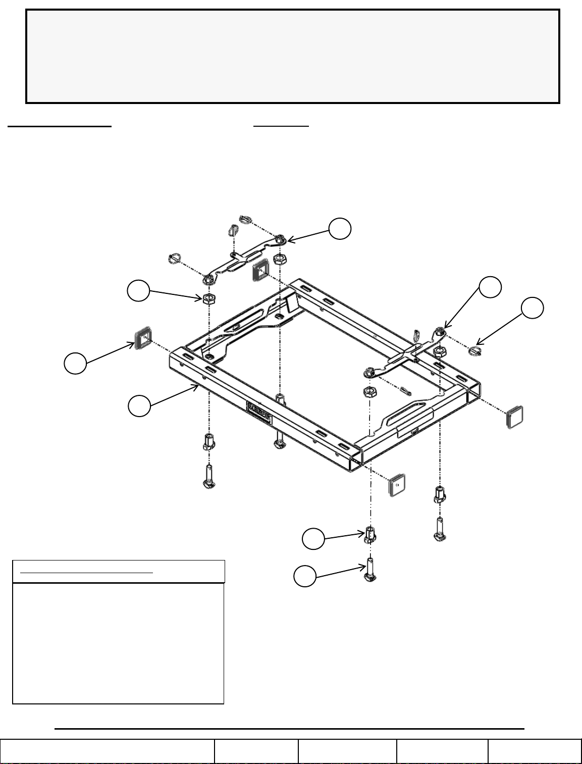
REF # QTY. DESCRIPTION
1 (1) ADAPTER WELDMENT
2 (4) ANCHOR, TEE PIN
3 (4) ANCHOR, BUSHING
4 (4) 1” JAM NUT
5 (2) HANDLE, LT ANCHOR
6 (2) HANDLE, RT ANCHOR
7 (6) LYNCH PIN
8 (4) END CAP
For Installation Assistance or Technical Help, Call 1-888-521-0510
© 2011 CequentPerformance Products, Inc. Made in XXX
SHEET 1 OF 5
3
2
30156N 08-08-11 Rev. A
Page 2
WARNING:
Failure to follow all of these instructions may result in death or serious injury
INDEX
1. SYSTEM ASSEMBLY P. 2 2. SYSTEM ADJUSTMENT P. 3
3. INSTALLATION P. 3 4. REMOVAL P. 4
5. BEFORE EACH TRIP/LUBRICATION P. 4 6. LIMITED LIFETIME WARRANTY P. 5
SYSTEM ASSEMBLY
REQUIRED TOOLS
• 1 ½” SOCKET AND MATCHING WRENCH (OR CRESENT WRENCH)
• RUBBER MALLET
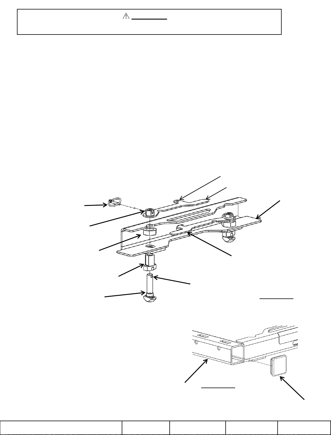
TEE PIN AND BUSHING ASSEMBLY
1. Assemble the four anchor bushings and the 1” jam nuts together (fig 1) and snug-fit (no vertical play in anchor bushing
assembly), then go another quarter turn beyond contact point for proper torque requirement.
2. Once all of the bushings and jam nuts are tight, assemble the tee pin and handle as shown (fig 1). (NOTE) When handles are
in locked position locking tab must protrude through slot in channel.
3. Tighten tee pin until there is metal to metal contact. Once this is accomplished loosen tee pin one-and-a-half rotations.
4. Align hole in tee pin and slot in handle nut, pin with included lynch pin.
5. Repeat steps 2, 3, 4 for remaining anchor bushings.
LOCKING TAB
HANDLE
LYNCH PIN
SLOT IN HANDLE NUT
1” JAM NUT
ANCHOR BUSHING
TEE PIN
End Cap Installation
1. Orient end cap as shown (fig 2), with ribs being inserted into
cross tube.
2. Insert end cap until flanged surface contacts edge of tube.
3. Repeat steps 1 and 2 for remaining end caps.
CHANNEL
HANDLE IN LOCKED POSITION
HOLE IN TEE PIN
FIGURE 1
© 2011 CequentPerformance Products, Inc. Made in XXX
CROSS TUBE
SHEET 2 OF 5
FIGURE 2
END CAP
30156N 08-08-11 Rev. A
Page 3
REESE Fifth Wheel Mounting Adapter Adjustment
Once the Reese Adapting Mounting Kit is assembled it will fit the average truck, however each truck is different.
Thus, possible adjustment might be required before the kit will work best.
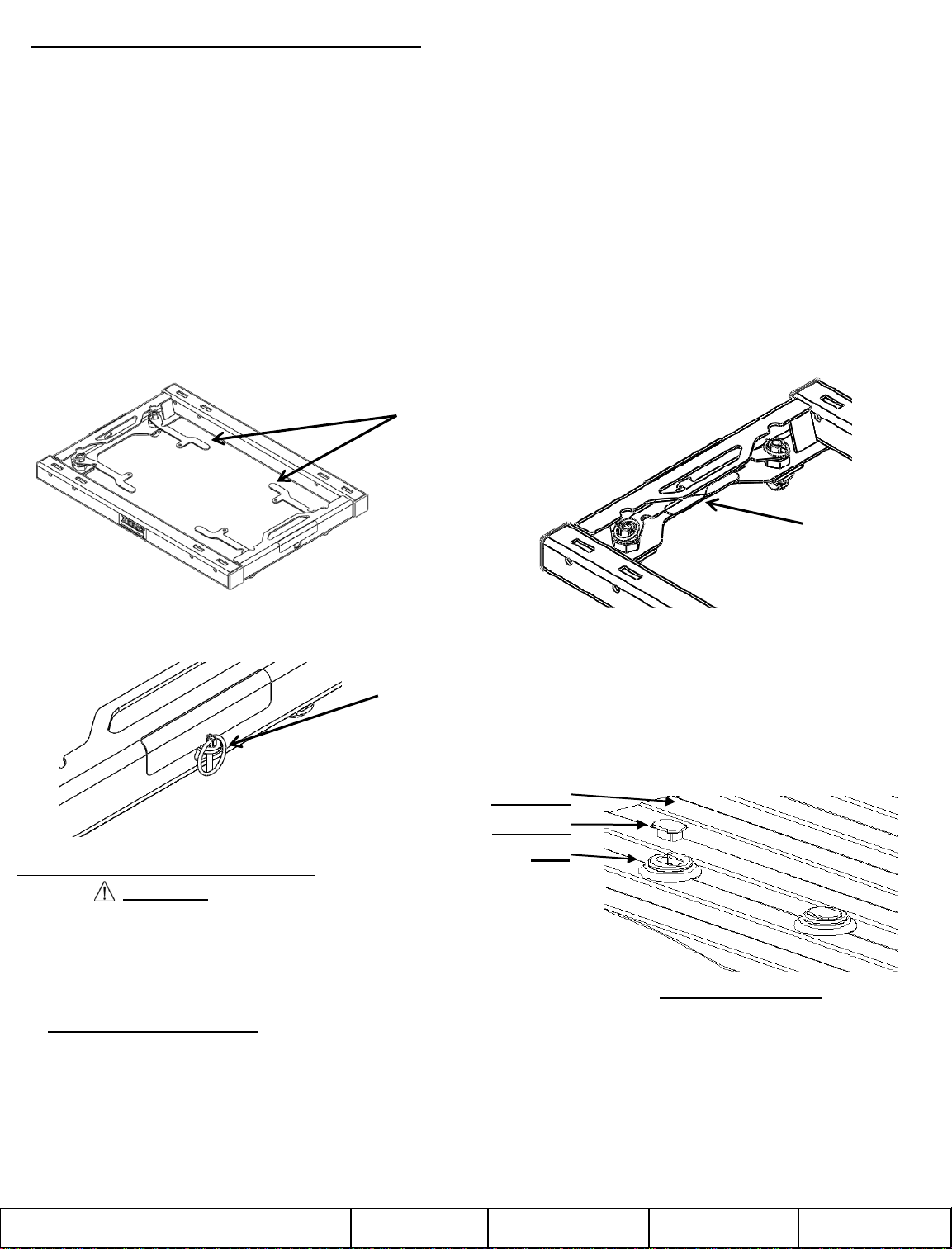
• Place unit into pucks with all handles in unlocked position (see Figure 3a). Rotate handles into locked position. It
is normal for some of the handles to have very little resistance, while others have a moderate amount of resistance
when locking. Should a handle not be able to be locked by hand; it needs to be adjusted.
• If the adapter does not fall into under bed mounting kit, when handles are in unlocked position, the tee pin bushing
needs adjustment. This can be done by loosening the four 1” jam nuts (refer to fig 1), while all nuts are loose drop
into the under bed mounting kit. While in place tighten jam nuts as described in the “system assembly” section.
• To adjust handle tension when locking; first remove adapter from pucks. Next, while keeping the handle to tee pin
orientation, remove the lynch pin. To loosen, rotate the tee pin counterclockwise ½ rotation, and replace lynch pin.
Conversely, if there is too much clearance in the attachments when locked, the clearance can be removed by
rotating the tee pin clockwise ½ rotation, and replacing the lynch pin. If adapter still will not securely pin into underbed mounting kit, or is still too loose, steps may need to be repeated.
Figure 3a. Anchor
handles in unlocked
position
WARNING:
Failure to properly install handles
could result in tow vehicle damage
or truck and trailer separation.
Figure 3b. Anchor
handles in locked
position (overlapped)
Figure 3c. Locking hole tabs in
handles overlap and protrude
through base arch, with lynch pins
in locked position.
Truck Bed
Puck Plug
Puck
Figure 4: Puck Plugs
ADAPTER INSTALLATION:
1. Remove puck plugs from all (4) of the pucks in the truck bed (Figure 4) and store for use when adapter is removed.
2. Set REESE mounting adapter onto the pucks, and rotate handles into unlocked position (approximately parallel
with base tube, (Figure 3a) until adapter drops into pucks on all (4) corners.
3. Rotate (4) handles into locked position(with locking hole tabs through base arch (Fig 3c) and overlapped on each
side (Figure 3b).
5. Place lynch pins / locks through the overlapping handle holes on each side to anchor hitch into pucks (Figure 3c).
© 2011 CequentPerformance Products, Inc. Made in XXX
SHEET 3 OF 5
30156N 08-08-11 Rev. A
Page 4
ADAPTER REMOVAL
1. Remove lynch pin / lock from the overlapping handle holes on each side of the adapter (Figure 3c). Store
lynch pins.
2. Rotate (4) handles into unlocked position (parallel with base tube, Figure 3a). Lift each side of adapter out
of pucks separately, handles may have to be worked slightly to align anchors with puck holes to remove.
3. Store adapter in dry place where dirt and debris will not get into anchor assemblies.
4. Press puck plugs (packed with mounting kit) into all (4) of the pucks in the truck bed to keep debris out of
pucks (Figure 4).
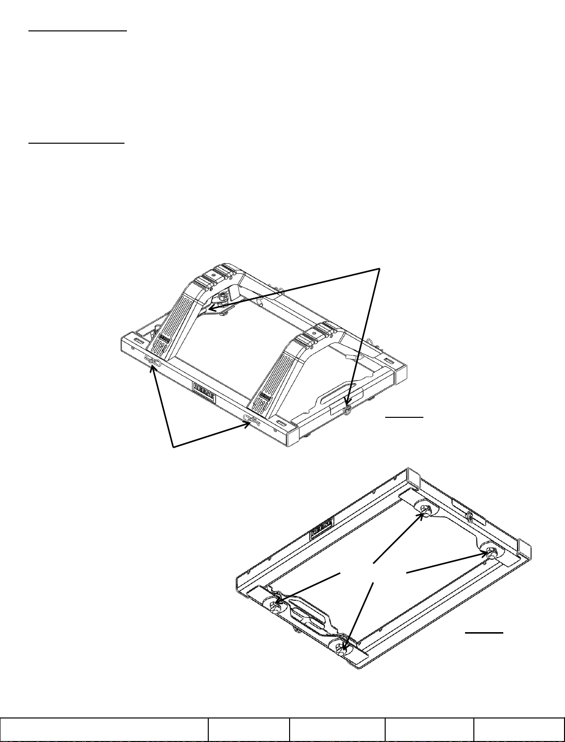
BEFORE EACH TRIP
1. Lube feet with lithium grease for easier engagement as shown in Figure 6
2. Before each trip or maneuver, check to make sure both the Tee pin arms as well as the pull pin (included in
fifth wheel hitch hardware bag) are in place and have respective lynch pins locked in place.
3. Review operation manuals for both the fifth wheel hitch being used, and the corresponding Elite or Signature
Series mounting kit being used.
Arms are in locked
position and lynch pin is
secured in place
Pull pins are in position, locking
arches and adapter together,
spring clips are in corresponding
groove in pull pin
Figure 5
Lube Points
Figure 6
© 2011 CequentPerformance Products, Inc. Made in XXX
SHEET 4 OF 5
30156N 08-08-11 Rev. A
Page 5

LIMITED LIFETIME WARRANTY
NOTES
Part No: Date of Original Purchase: _
Original Owner: Original Installer: _
1. Limited Lifetime Warranty (“Warranty”). Cequent Performance Products, Inc. ("We" or “Us”) warrants to the original
consumer purchaser only ("You") that the product will be free from material defects in both material and workmanship,
ordinary wear and tear excepted; provided that installation and use of the product is in accordance with product instructions.
There are no other warranties, express or implied, including the warranty of merchantability or fitness for a particular purpose.
This warranty is not transferable.
2. Limitations on the Warranty. This Warranty does not cover: (a) normal wear and tear; (b) damage through abuse, neglect,
misuse, or as a result of any accident or in any other manner; (c) damage from misapplication, overloading, or improper
installation; (d) improper maintenance and repair; and (e) product alteration in any manner by anyone other than Us, with the
sole exception of alterations made pursuant to product instructions and in a workmanlike manner.
3. Obligations of Purchaser. To make a Warranty claim, contact Us, at our principal address of 47912 Halyard Dr. Suite 100,
Plymouth, MI 48170, 1-888-521-0510, identify the product by model number, and follow the claim instructions that will be
provided. Any returned product that is replaced by Us becomes our property. You will be responsible for return shipping costs.
Please retain your purchase receipt to verify date of purchase and that You are the original consumer purchaser. The product
and the purchase receipt must be provided to Us in order to process Your Warranty claim.
4. Remedy Limits. Product replacement is Your sole remedy under this Warranty. We shall not be liable for service or labor
charges incurred in removing or replacing a product or any incidental or consequential damages of any kind.
5. Assumption of Risk. You acknowledge and agree that any use of the product for any purpose other than the specified
use(s) stated in the product instructions is at Your own risk.
6. Governing Law. This Warranty gives You specific legal rights, and You also may have other rights which vary from state to
state. This Warranty is governed by the laws of the State of Michigan, without regard to rules pertaining to conflicts of law. The
state courts located in Oakland County, Michigan shall have exclusive jurisdiction for any disputes relating to this Warranty.
© 2011 CequentPerformance Products, Inc. Made in XXX
Cequent Performance Products, Inc.
47912 Halyard Dr. Suite 100
Plymouth, MI 48170
SHEET 5 OF 5
30156N 08-08-11 Rev. A
Page 6

INSTRUCCIONES
KIT ADAPTADOR DE MONTAJE # 30156 PARA ENGANCHE DE 5TA.
RUEDA REESE
SAE J2638 CALIFICADO PARA 20.000 LB PESO BRUTO DE REMOLQUE
CONCESIONARIO/INSTALADOR:
1. Entregue este manual al usuario final.
2. Demuestre físicamente los procedimientos de
instalación y remoción en este manual al usuario final.
3. Pida al usuario final que le demuestre que entiende
los procedimientos.
4
8
1
USUARIO FINAL:
1. Lea y siga este manual todas las veces que use el adaptador.
2. Guarde este Manual para referencia futura.
3. Distribuya este manual a cualquier otro usuario o propietario del adaptador.
4. Nunca quite las etiquetas de advertencia del adaptador. En caso de daños
contacte a Cequent Performance Products, Inc.
(1-888-521-0510) para reemplazos gratuitos.
5
6
7
3
REF # CANT. DESCRIPCIÓN
1 (1) SOLDADURA DEL ADAPTADOR
2 (4) ANCLAJE, PASADOR EN T
3 (4) ANCLAJE, CASQUILLO
4 (4) TUERCA DE BLOQUEO DE 1"
5 (2) MANIJA, ANCLAJE IZQ.
6 (2) MANIJA, ANCLAJE DER.
7 (6) PASADOR DE EJE
8 (4) TAPA EXTREMO
2
Para asistencia con la instalación o ayuda técnica, llame al 1-888-521-0510
© 2011 CequentPerformance Products, Inc. Made in XXX
Hoja 1 de 5
30156N 08-08-11 Rev. A
Page 7

ADVERTENCIA:
¡No seguir estas instrucciones puede resultar en la muerte o en lesiones de gravedad!
ÍNDICE
1. ENSAMBLE DEL SISTEMA P. 2 2. AJUSTE DEL SISTEMA P. 3
3. INSTALACIÓN P. 3 4. REMOCIÓN P. 4
5. ANTES DE CADA VIAJE/LUBRICACIÓN: P. 4 GARANTÍA LIMITADA DE POR VIDA P. 5
ENSAMBLE DEL SISTEMA
HERRAMIENTAS NECESARIAS
• TUBO Y LLAVE CORRESPONDIENTE (O LLAVE AJUSTABLE) DE 1 1/2"
• MAZO DE GOMA
ENSAMBLE DE PASADOR EN T Y CASQUILLOS
1. Instale los cuatro casquillos de anclaje y las tuercas de bloqueo de 1" juntos (fig 1) y haga un ajuste ceñido (sin juego vertical en
el ensamble de los casquillos de anclaje), luego haga otro cuarto de giro más allá del punto de contacto para el requisito
correcto de torsión.
2. Una vez que todos los casquillos y las tuercas de bloqueo estén apretados, instale el pasador en T y la manija como se muestra
(Fig. 1). (NOTA) Cuando las manijas estén en la posición de bloqueo, la pestaña de bloqueo debe sobresalir a través de la
ranura en el canal.
3. Apriete el pasador en T hasta que haya contacto de metal con metal. Una vez logrado esto afloje el pasador en T uno y medio
giros.
4. Alinee el agujero en el pasador en T y la ranura en la tuerca de manija, bloquee con el pasador de eje incluido.
5. Repita los pasos 2, 3, 4 para el resto de los casquillos de anclaje.
PESTAÑA DE BLOQUEO
PASADOR
DE EJE
RANURA EN TUERCA DE MANIJA
TUERCA DE BLOQUEO, 1"
CASQUILLOS DE ANCLAJE
PASADOR EN T
INSTALACIÓN DE TAPA EXTREMO
1. Oriente la tapa extremo como se muestra (fig. 2), con los
rebordes insertados dentro del travesaño.
2. Inserte la tapa extremo hasta que la superficie con reborde
haga contacto con el borde del tubo.
3. Repita los pasos 1 y 2 para las tapas extremo restantes.
MANIJA
CANAL
MANIJA EN POSICIÓN DE BLOQUEO
AGUJERO EN EL PASADOR EN T
FIGURA 1
© 2011 CequentPerformance Products, Inc. Made in XXX
Hoja 2 de 5
TRAVESAÑO
FIGURA 2
TAPA
EXTREMO
30156N 08-08-11 Rev. A
Page 8

Ajuste del adaptador de montaje de quinta rueda REESE
Una vez que el kit de montaje de adaptación Reese se ensamble, se ajustará en un vehículo promedio, sin embargo
cada vehículo es diferente. Por lo tanto, podría ser posible un ajuste antes de que el kit pueda funcionar de manera ideal.
• Coloque la unidad dentro de discos con todas las manijas en la posición abierta (ver Figura 3a). Gire las manijas a la
posición de bloqueo. Es normal que algunas manijas tengan muy poca resistencia, mientras que otras tengan una
resistencia moderada al bloquearse. En caso de que una manija no se pueda bloquear a mano, deberá ajustarse.
• Si el adaptador no cae dentro del kit de montaje debajo de la base, cuando las manijas se encuentran en posición
abierta, el casquillo del pasador en T necesita ajuste. Esto se puede hacer aflojando las cuatro tuercas de bloqueo de
1" (ver fig 1), mientras que todas las tuercas se dejan caer flojas dentro del kit de montaje debajo de la base. Mientras
están en su lugar apriete las tuercas de bloqueo como se describe en la sección de Ensamble del sistema.
• Para ajustar la tensión de la manija cuando se bloquea, primero retire el adaptador de los discos. A continuación,
manteniendo la manija en la orientación del pasador en T, retire el pasador de eje. Para aflojar, gire el pasador en T
hacia la izquierda media rotación, y reemplace el pasador de eje. De manera opuesta, si hay demasiado despeje en
las uniones cuando se cierran, se puede eliminar el despeje al rotar el pasador en T ½ giro hacia la derecha, y
reemplazar el pasador de eje. Si el adaptador todavía no encaja de forma segura dentro del kit de montaje debajo de
la base, o si todavía está demasiado flojo, podría ser necesario repetir los pasos.
Figura 3a. Manijas
de anclaje en
posición abierta
Figura 3b. Manijas de
anclaje en posición
cerrada (traslapadas)
Figura 3c. Las lengüetas del
orificio de bloqueo en las manijas
se traslapan y sobresalen a través
del arco de base, con los
pasadores de eje en posición de
bloqueo.
Base del vehículo
Tapón de disco
Disco
ADVERTENCIA:
No instalar correctamente las manijas
podría resultar en daño al vehículo de
remolque o la separación del vehículo y
remolque.
Figura 4: Tapones de disco
INSTALACIÓN DEL ADAPTADOR:
1. Quite los tapones de disco de todos (4) los discos en la base del vehículo (Figura 4) y guarde para su uso cuando
se quite el adaptador.
2. Coloque el adaptador de montaje REESE sobre los discos y gire las manijas hacia la posición abierta
(aproximadamente en paralelo con el tubo de base), (Figura 3a) hasta que el adaptador se acomode en los discos
en todas las (4) esquinas.
3. Rote las (4) manijas hacia la posición de bloqueo (con las lengüetas del orificio de bloqueo a través del arco de
base (Fig. 3c) y traslapadas en cada lado (Figura 3b).
5. Coloque los pasadores de eje / bloqueos a través de los orificios de la manija traslapada en cada lado para anclar
el enganche dentro de los discos (Figura 3c).
© 2011 CequentPerformance Products, Inc. Made in XXX
Hoja 3 de 5
30156N 08-08-11 Rev. A
Page 9

REMOCIÓN DEL ADAPTADOR
1. Retire los pasadores de eje / bloqueo de los orificios de la manija traslapada en cada lado del adaptador (Figura
3c). Guarde los pasadores de eje.
2. Gire las (4) manijas hacia la posición abierta (paralela al tubo base, Figura 3a). Levante cada lado del adaptador
fuera de los discos por separado, es posible que haya que manipular un poco las manijas para alinear los anclajes
con los orificios de los discos para retirar.
3. Guarde el adaptador en un lugar seco donde la suciedad y los escombros no entren en los ensambles del anclaje.
4. Coloque a presión los tapones de los discos (vienen con el kit de montaje) en todos los (4) discos en la base del
vehículo para mantener la suciedad fuera de los discos (Figura 4).
ANTES DE CADA VIAJE
1. Lubrique las patas con grasa de litio para facilitar la activación como se muestra en la Figura 6
2. Antes de cada viaje o maniobra, compruebe que tanto los brazos de pasador en T, como el pasador de halar
(incluido en la bolsa de piezas del enganche de quinta rueda) estén en su lugar y tengan los respectivos
pasadores de eje bloqueados en su lugar.
3. Revise los manuales de operación tanto para el enganche de quinta rueda que se está usando como para el kit de
montaje correspondiente de la Serie Elite o Signature que se está usando.
Los brazos están en
posición de bloqueo y los
pasadores de eje están
fijos en su lugar.
Los pasadores de halar están en
posición, bloqueando los arcos y el
adaptador juntos, los pasadores de
resorte están en la ranura
correspondiente en el pasador de
halar
Figura 5
Puntos de lubricación
Figura 6
© 2011 CequentPerformance Products, Inc. Made in XXX
Hoja 4 de 5
30156N 08-08-11 Rev. A
Page 10

GARANTÍA LIMITADA DE POR VIDA
NOTAS:
Número de parte: Fecha de compra original:________________
Propietario original: Instalador original:______________________
1. GARANTÍA DE POR VIDA LIMITADA (Garantía) Cequent Performance Products, Inc. ("Nosotros” o “Nuestro”) garantiza al
comprador minorista original únicamente ("usted") que el producto estará libre de defectos materiales y de mano de obra, con
la excepción del uso y desgaste habitual, siempre y cuando la instalación y el uso del producto esté de acuerdo con las
instrucciones del producto. No existen otras garantías, expresas o implícitas, incluida la garantía de comerciabilidad o
idoneidad para un propósito en particular. Esta garantía no es transferible.
2. Limitaciones de la garantía. Esta garantía limitada no cubre lo siguiente: (a) desgaste normal y habitual; (b) daño por
abuso, negligencia, mal uso, o como resultado de cualquier accidente o de cualquier otra manera; (c) daño por aplicación o
instalación incorrectas o sobrecarga; (d) mantenimiento y reparación incorrectos; y (e) alteración del producto de cualquier
manera por alguien que no seamos nosotros, con la única excepción de alteraciones realizadas de acuerdo con las
instrucciones del producto y de una manera profesional.
3. Obligaciones del comprador. Para hacer una reclamación de garantía, contáctenos en nuestra dirección principal en 47912
Halyard Dr. Suite 100, Plymouth, MI 48170, 1-888-521-0510, identifique el producto por número de modelo y siga las
instrucciones que se le darán para la reclamación. Cualquier producto devuelto que se reemplace o se reembolse se
convierte en propiedad nuestra. Usted será responsable por los costos de envío del producto. Conserve el recibo de compra
para verificar la fecha de compra y que usted es el comprador original. Nos debe entregar el producto y el recibo de compra
para procesar su reclamo de garantía.
4. Límites de compensación. La sustitución del producto es su único recurso bajo esta garantía. No seremos responsables
por el servicio o cargos de mano de obra en los que se incurra al quitar o reemplazar un producto o cualquier daño de
cualquier tipo.
5. Riesgo asumido Usted reconoce y acepta que cualquier uso del producto para cualquier propósito diferente al uso(s)
especificado(s) en las instrucciones del producto es a su propio riesgo.
6. Ley gobernante. Esta garantía le otorga derechos legales. Usted también podría tener otros derechos que varían de estado
a estado. Esta garantía está regida por las leyes del estado de Michigan, sin importar las normas relativas a conflictos de Las
cortes estatales ubicadas en el condado de Oakland, Michigan tendrán la jurisdicción exclusiva para cualquier disputa que
surja con respecto a esta garantía.
Cequent Performance Products, Inc.
47912 Halyard Dr. Suite 100
Plymouth, MI 48170
© 2011 CequentPerformance Products, Inc. Made in XXX
Hoja 5 de 5
30156N 08-08-11 Rev. A
Page 11

INSTRUCTIONS
REESE 5 #30156
HOMOLOGUÉ SAE J2638 POUR UN POIDS BRUT DE REMORQUE DE 20,000 LB
CONCESSIONNAIRE/INSTALLATEUR :
1. Remettre ce manuel à l'utilisateur final.
2. Démontrez physiquement à l'utilisateur les
procédures de montage et de démontage décrites
dans ce manuel.
3. Demander à l'utilisateur final de démontrer sa
compréhension des procédures.
4
8
UTILISATEUR FINAL :
1. Lire et observer les instructions de ce manuel à chaque utilisation de
l'adaptateur.
2. Conserver ce manuel pour consultation ultérieure.
3. Remettre des copies du Manuel à tout autre utilisateur ou propriétaire.
4. Ne jamais enlever les décalcomanies d'avertissement sur l'adaptateur. Si
les décalcomanies sont endommagées, contactez Cequent Performance
Products, Inc. (1-888-521-0510) pour les remplacer gratuitement.
5
6
7
1
No RÉF QTÉ DESCRIPTION
1 (1) ENSEMBLE SOUDÉ DE L'ADAPTATEUR
2 (4) ANCRAGE, CHEVILLE EN T
3 (4) ANCRAGE, MANCHON
4 (4) CONTRE-ÉCROU 1”
5 (2) LEVIER, ANCRAGE GAUCHE
6 (2) LEVIER, ANCRAGE DROIT
7 (6) GOUPILLE À ANNEAU
8 (4) CAPUCHON D'EXTRÉMITÉ
Pour obtenir de l'assistance pour l'installation ou
un autre aspect technique, composer le 1-888-521-0510
3
2
© 2011 CequentPerformance Products, Inc. Made in XXX
FEUILLE 1 de 5
30156N 08-08-11 Rev. A
Page 12

AVERTISSEMENT :
L'omission d'observer toutes les instructions
peut causer des blessures sévères, voire la mort !
SOMMAIRE
1. MONTAGE DE L'ENSEMBLE P. 2 2. AJUSTEMENT DE L'ENSEMBLE P. 3
3. INSTALLATION P. 3 4. ENLÈVEMENT P. 4
5. AVANT CHAQUE DÉPLACEMENT/LUBRIFICATION P. 4 6. GARANTIE LIMITÉE À VIE P. 5
MONTAGE DE L'ENSEMBLE
OUTILS REQUIS
• DOUILLE 1 ½” ET CLÉ CORRESPONDANTE (OU CLÉ CRESCENT)
• MAILLET EN CAOUTCHOUC
ASSEMBLAGE CHEVILLE EN T ET MANCHON
1. Assembler les quatre manchons d'ancrage avec les contre-écrous 1 po (fig 1) et serrer à fond (aucun jeu dans l'assemblage des
manchons), puis serrer un quart de tour supplémentaire au-delà du point de contact pour obtenir le couple de serrage requis.
2. Une fois tous les manchons et les contre-écrous bien serrés, assembler la cheville en T et le levier comme illustré (fig. 1).
(NOTE) Lorsque les leviers sont en position de verrouillage, la languette de verrouillage doit dépasser de la fente du profilé.
3. Serrer la cheville en T jusqu'à obtenir un contact métal à métal. Ensuite, desserrer la cheville en T d'un tour et demi.
4. Aligner le trou de la cheville en T sur la fente de l'écrou à levier, puis verrouiller à l'aide de la goupille à anneau.
5. Répéter les étapes 2, 3, 4 pour les autres manchons.
GOUPILLE À ANNEAU
LANGUETTE DE VERROUILLAGE
LEVIER
PROFILÉ
FENTE DE L'ÉCROU
À LEVIER
CONTRE-ÉCROU 1”
MANCHON D'ANCRAGE
CHEVILLE EN T
INSTALLATION DES CAPUCHONS D'EXTRÉMITÉ
1. Orienter le capuchon comme illustré (fig 2), ailes insérées dans
le tube.
2. Insérer le capuchon jusqu'à ce que ses rebords s'appuient sur
les arêtes du tube.
3. Répéter les étapes 1 et 2 pour les autres capuchons.
TRAVERSE TUBULAIRE
LEVIER EN POSITION
DE VERROUILLAGE
TROU DE LA CHEVILLE EN T
FIGURE 1
FIGURE 2
© 2011 CequentPerformance Products, Inc. Made in XXX
FEUILLE 2 DE 5
CAPUCHON
D'EXTRÉMITÉ
30156N 08-08-11 Rev. A
Page 13

Ajustement de l'adaptateur de montage de l'attelage à sellette REESE
Une fois monté, l'ensemble adaptateur Reese s'adaptera à la plupart des camionnettes, cependant chaque modèle est
différent. Par conséquent, il se peut que des ajustements soient requis pour obtenir la meilleure adaptation possible.
• Placer l'ensemble dans les réceptacles avec les leviers en position de déverrouillage (voir la Figure 3a). Faire pivoter
les leviers en position de verrouillage. Il est normal que certains leviers offrent de la résistance contrairement à d'autres
au moment du verrouillage. Il faut ajuster un levier que l'on arrive pas à verrouiller à la main.
• Si l'adaptateur ne s'insère pas dans le dispositif de montage sous la plateforme de la camionnette lorsque les leviers
sont en position de déverrouillage, alors les manchons des chevilles en T nécessitent un ajustement. Cela peut
s'effectuer en desserrant les quatre contre-écrous de 1 po (voir la fig. 1), tandis que tous les écrous sont desserrés dans
le dispositif de montage sous la plateforme. Tandis qu'ils sont en place, desserrer les contre-écrous tel que décrit dans
la section « Montage de l'ensemble ».
• Pour ajuster la tension du levier lors du verrouillage, retirer d'abord l'adaptateur des réceptacles. Ensuite, tout en
maintenant le levier dans l'orientation de la cheville, retirer la goupille à anneau. Pour desserrer, tourner la cheville en T
d'un demi-tour dans le sens contraire des aiguilles, puis replacer la goupille à anneau. À l'inverse, s'il y a trop de jeu
dans la fixation lors du verrouillage, tourner la cheville d'un demi-tour dans le sens des aiguilles, puis replacer la
goupille. Si l'adaptateur ne s'insère toujours pas fermement dans le dispositif de montage sous plateforme, ou s'il
présente encore du jeu, les étapes précédentes doivent être recommencées.
Figure 3a. Leviers
d'ancrage en position
de déverrouillage
AVERTISSEMENT :
L'installation incorrecte des leviers peut
causer l'endommagement du véhicule ou la
séparation du véhicule et de la caravane.
INSTALLATION DE L'ADAPTATEUR :
Figure 3b. Leviers
d'ancrage en position de
verrouillage (superposés)
Figure 3c. Les languettes de verrouillage des leviers se
superposent et dépassent de la pièce transversale, avec
goupilles à anneau en position de verrouillage.
Plateforme de la camionnette
Bouchon de réceptacle
Réceptacle
Figure 4 : Bouchons de réceptacle
1. Retirer les bouchons (4) des réceptacles de la plateforme de la camionnette (Figure 4) et les conserver pour leur
réutilisation lors du retrait de l'adaptateur.
2. Placer l'adaptateur REESE sur les réceptacles et tourner les leviers en position de déverrouillage (approx. parallèles à
la pièce transversale - Figure 3a) jusqu'à ce que l'adaptateur s'insère dans les récepteurs aux quatre (4) coins.
3. Tourner les quatre (4) leviers en position de verrouillage, languettes de verrouillage traversant la pièce transversale
(Fig. 3c) et se superposant de chaque côté (Figure 3b).
5. Placer les goupilles à anneau / verrous dans les trous superposés des leviers de chaque côté afin d'ancrer l'adaptateur
dans les réceptacles (Figure 3c).
© 2011 CequentPerformance Products, Inc. Made in XXX
FEUILLE 3 DE 5
30156N 08-08-11 Rev. A
Page 14

ENLÈVEMENT DE L'ADAPTATEUR
1. Retirer les goupilles à anneau / verrous des trous superposés des leviers de chaque côté de l'adaptateur
(Figure 3c). Conserver les goupilles à anneau.
2. Tourner les quatre (4) en position de déverrouillage (parallèlement à la pièce transversale, Figure 3a).
Soulever chaque côté de l'adaptateur séparément pour les extraire du réceptacle, ne pas hésiter à
déplacer les leviers légèrement pour aligner les ancrages sur les trous des réceptacles.
3. Ranger l'adaptateur dans un endroit sec où la saleté et les particules ne pénétreront pas dans les
ancrages.
4. Enfoncer les bouchons (emballés avec le nécessaire de montage) dans les quatre (4) réceptacles de la
plateforme pour empêcher les particules d'y pénétrer (Figure 4).
AVANT CHAQUE DÉPLACEMENT
1. Lubrifier les pieds avec de la graisse au lithium pour faciliter l'insertion, comme illustré à la Figure 6.
2. Avant chaque déplacement ou manoeuvre, s'assurer que les bras des chevilles en T de même que la
cheville des arches de support (incluse dans le sac de ferronnerie de l'attelage à sellette) sont bien en place
et que leurs goupilles respectives sont bien verrouillées.
3. Prendre connaissance des modes d'emploi de l'attelage à sellette et du nécessaire de montage Elite ou
Signature Series correspondant qui sont utilisés.
Les bras sont en position
verrouillée et la goupille à
anneau est fixée en place.
Les chevilles d’arches sont en position,
verrouillant les arches de support et
l'adaptateur ensemble, les goupilles à
ressort sont dans les nervures
correspondantes de la cheville d'arche.
Figure 5
Points de lubrification
Figure 6
© 2011 CequentPerformance Products, Inc. Made in XXX
FEUILLE 4 DE 5
30156N 08-08-11 Rev. A
Page 15

REMARQUES
GARANTIE À VIE LIMITÉE
No pièce : Date de l'achat initial : _
Propriétaire initial : Installateur initial : _
1. Garantie à vie limitée (« Garantie »). Cequent Performance Products, Inc. (« Nous ») garantit à l’acheteur initial seulement
(« Vous ») que le produit sera exempt de vices de matières et de fabrication, exception faite de l’usure normale, dans la
mesure où l’installation et l’utilisation du produit sont conformes aux instructions accompagnant celui-ci. Aucune autre
garantie, expresse ou implicite, ne s’applique, y compris les garanties relatives à la qualité marchande ou à l'adéquation à un
usage particulier. Cette garantie n’est pas transférable.
2. Limites de la garantie. Cette garantie ne couvre pas : (a) l’usure normale; (b) les dommages causés par l’abus, la
négligence, une mauvaise utilisation, ou résultant de tout accident survenu de quelque manière que ce soit; (c) les dommages
causés par une application inappropriée, une charge excessive ou une installation inadéquate; (d) un entretien ou une
réparation inadéquate; (e) un produit modifié de quelque manière que ce soit par quiconque d’autre que Nous, à l’exception
des modifications stipulées dans les instructions accompagnant le produit et réalisées selon les règles de l’art.
3. Obligations de l’acheteur. Pour effectuer une réclamation, communiquez avec nous à notre adresse principale,
47912Halyard Dr. Suite 100, Plymouth, MI 48170, 1-888-521-0510, et veuillez identifier le produit d'après le numéro de
modèle et suivre les directives qui vous seront fournies. Tout produit retourné qui est remplacé par Nous devient notre
propriété. Vous serez tenu d’assumer les frais d’expédition de retour. Veuillez conserver votre reçu d’achat afin que nous
puissions en vérifier la date et confirmer que Vous êtes l'acheteur initial. Le produit et le reçu d’achat doivent Nous être fournis
afin que nous puissions traiter Votre réclamation.
4. Limites des recours. Le remplacement du produit est Votre seul recours en vertu de cette Garantie. Nous ne sommes pas
responsables des frais de service ou de main-d’oeuvre encourus pour l’enlèvement ou la réinstallation d’un produit, ni des
dommages accessoires ou indirects, quels qu’ils soient.
5. Acceptation des risques. Vous reconnaissez et acceptez que toute utilisation du produit à des fins autres que celle(s)
stipulée(s) dans les instructions relatives au produit est faite à vos propres risques.
6. Loi applicable. Cette Garantie Vous confère des droits légaux spécifiques, et il se peut que Vous possédiez d’autres droits
qui peuvent varier d’une province à l’autre. Cette Garantie est régie par les lois de l’État du Michigan, abstraction faite des
règles relatives aux conflits de lois. Les cours de l’État situées dans le comté d’Oakland, Michigan, constituent les autorités
judiciaires exclusives relativement à tout litige relevant de cette Garantie.
© 2011 CequentPerformance Products, Inc. Made in XXX
Cequent Performance Products, Inc.
47912 Halyard Dr., Suite 100
Plymouth, MI 48170
FEUILLE 5 DE 5
30156N 08-08-11 Rev. A
 Loading...