

Page 1
ASSEMBLY INSTRUCTIONS
FIFTH WHEEL SLIDER HITCH
(2) Save this Manual for future reference
16.
GRIP, HEAD HANDLE
1
24.1/2 BOLT
2
Elite Series
DEALER/INSTALLER:
(1) Provide this Manual to end user.
(2) Physically demonstrate procedures in this Manual to end user.
(3) Have end user demonstrate that he/she understands procedures.
END USER:
(1) Read and follow this Manual every time you use Hitch.
.
(3) Pass on copies of Manual to any other user or owner of Hitch.
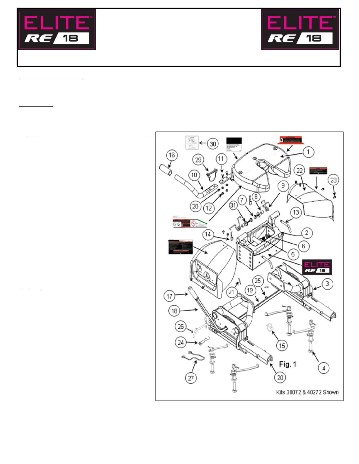
PART
1. HEAD ASSEMBLY 1
2. CENT E R S E CTION 1
3. SLI DE R ASSEMBLY - LH & RH 2
4. ANCHOR ASSE MBLY 4
ANCHOR TEE PI N ( 4)
HANDLE R (2) & L ( 2)
1" J AM NUT ( 4)
3/16" COTTER PIN (4)
ANCHOR B USHING (4)
5. 5/8" -11 GRADE 8 HEX HEA D B OLT 4
6. 5/8" LOCK WASHER 4
7. THUMB SCREW 2
8. TUBE SPACER 2
9. TORSI ON SPRING - LH & RH 2
10. HANDLE T UB E 1
11. 3/8" CARRIAGE BOLT 2
12. 3/8" NUT, USE ON HANLE TUB E 2
13. 1/2" P ULL P IN 2
14. SPRING RETA INING CLIP 2
15. LYNCH PIN 2
17. GRIP, SLIDER HA NDLE 1
18. SLI DE R HANDLE 1
19. CONNE CTOR TUB E 1
20. SLIDER RAIL 2
21. 5/32" COTTER P IN 2
22. SLI DE R ASSEMBLY COVER - LH & RH 2
23. 1/4" SHEET MET AL SCREW 8
"
25. 1/2" LOCK NUT, US E ON 1/2" BOLT 2
26. LOCK P IN AND CLIP 1
27. NYLON LANY ARD 1
28. 3/8" LOCK WASHER 2
29. BA I L PI N 1
30. HANG TAG 1
31. 1/4" FENDER WASHER 2 FOR 18K KITS
QTY.
For Installation Assistance or Technical Help, Call 1-888-521-0510
30144N– 05JUL10A PCN13292 ©2010 CEQUENT PERFORMANCE PRODUCTS, INC. Litho in USA 1
For Kit 30144
Page 2
WARNING:
1. GUIDELINES FOR MATCHING TOW VEHICLE AND TRAILER
P. 2
4
WARNING:
). (
)
)(
g
)
Vehicle T
4. A
15%
25% of trail
hitch (Pin Weight)
15-25%
Failure to follow all of these instructions may result in death or serious injury!
INDEX
-
2. PLASTIC BED LINER INSTRUCTIONS P. 5
3. ASSEMBLY INSTRUCTIONS P. 6-16
4. CEQUENT PERFORMANCE PRODUCTS, INC. SEVEN YEAR LIMITED
WARRANTY P. 17
GUIDELINES FOR MATCHING HITCH TRUCK AND TRAILER
Failure to check and follow tow ratings could result in tow vehicle
damage or truck and trailer separation while hauling.
•Trailer and its contents together must not exceed truck, hitch and/or trailer tow
ratings.
•Towing vehicle must have a manufacturer’s rated towing capacity equal to or
greater than the gross trailer weight (dry weight of the trailer plus payload of the
trailer
•Gross weight of trailer must not exceed 18,000 pounds.
•King pin weight must not exceed 4,000 pounds.
•(See Fig. 3). If in doubt have king pin weight measured by qualified facility.
See Fig. 2
FACTORY TRAILER + FULL WATER
TANKS + CARGO, ETC.
= GROSS TRAILER WEIGHT
Fig. 2
1. Check Tow Ratings:
ow Rating:_______________________.
Elite Series Hitch Rating:_______ __.
Gross Trailer Weight (Fig. 2):______________.
*Trailer weight should be the lowest of these recorded ratings for safe towing conditions.
2. Cequent Performance Products, Inc. hitches are designed for use with recreational fifth wheel trailers only. Hitch
applications other than recreational fifth wheel trailers must be approved in writing by Cequent Performance
Products, Inc. Engineering Department.
3. Use only a SAE 2-inch kingpin with your
pproximately
Fig. 3
-
er weight should be on
Elite Series Fifth Wheel Hitch.
. See Fig. 3.
GROSS TRAILER
WEIGHT
(PIN WEIGHT)
30144N– 05JUL10A PCN13292 ©2010 CEQUENT PERFORMANCE PRODUCTS, INC. Litho in USA 2
For Kit 30144
75-85%
GROSS TRAILER
WEIGHT
Page 3
5. Trucks come in many different configurations. Cequent Performance Products, Inc hitches are designed for use in light
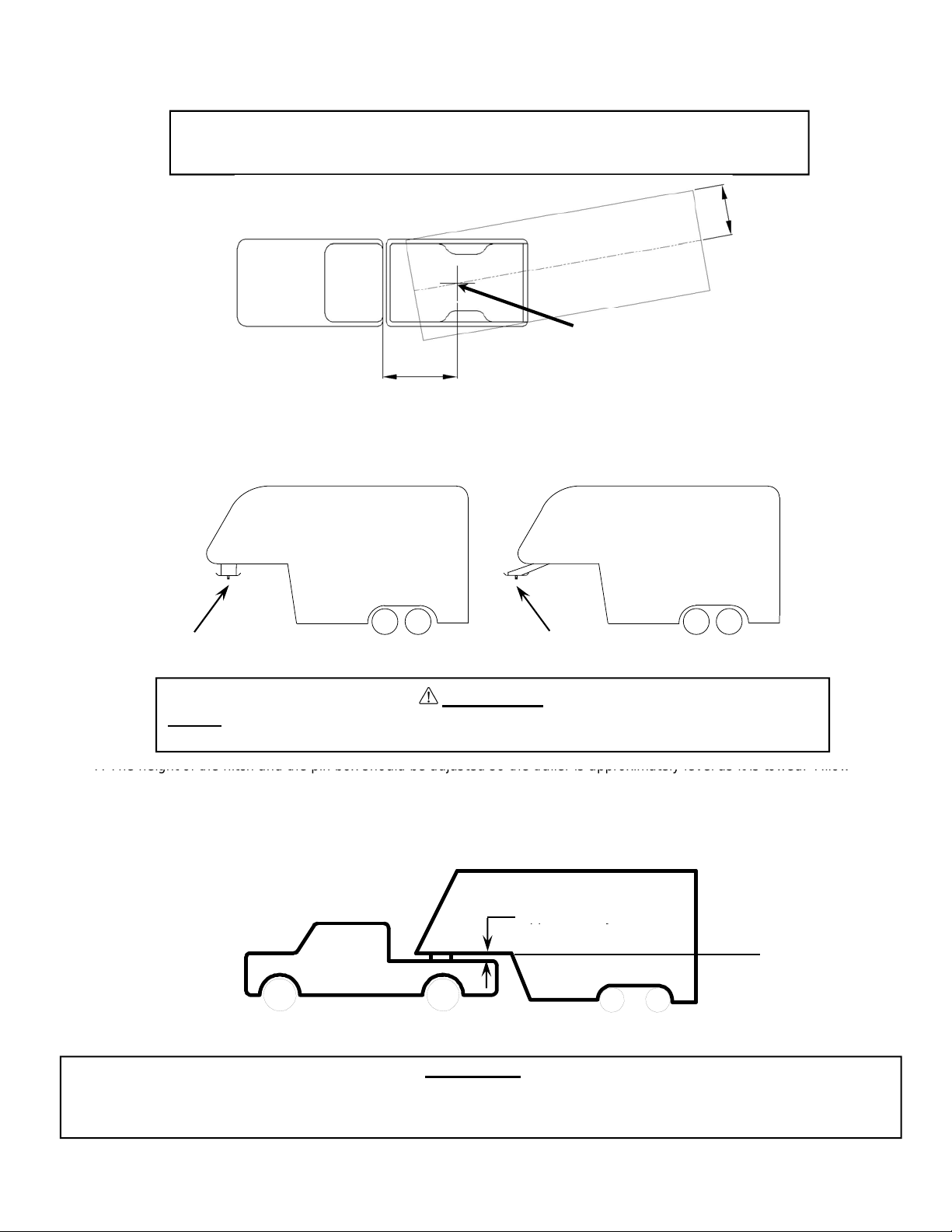
7. The height of the hitch and the pin box should be adjusted so the trailer is approximately level as it is towed. Allow
pp y
trucks such as the Ford F-Series, the Chevy Silverado and the Dodge Ram. Cequent Performance Products Inc.
recommends the use of long bed (8ft) light trucks for the best combination in truck - trailer turning clearance.
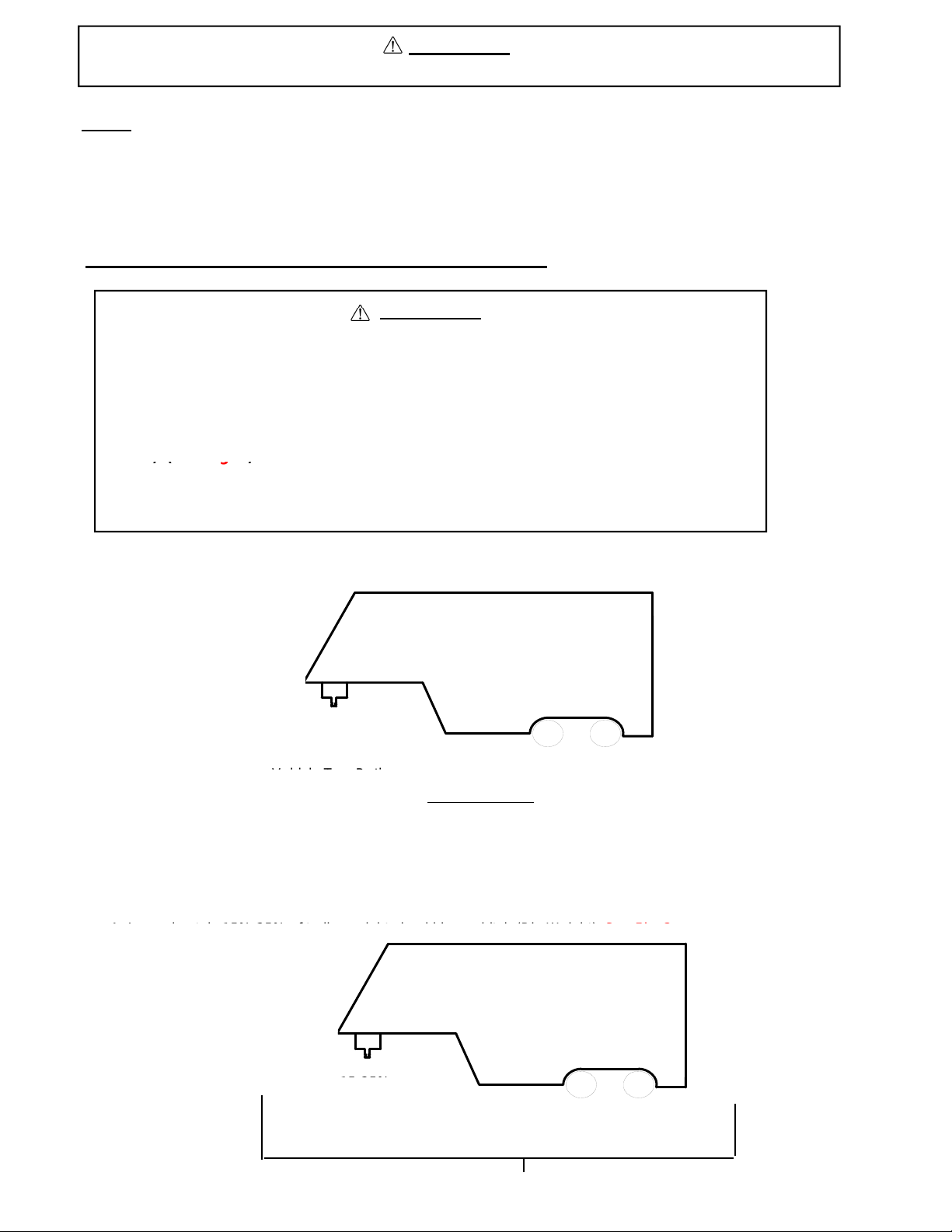
Rule of thumb: The distance from the back of the truck cab to the center of the rear truck
axle (“X” in Fig. 4), should be approximately 4 inches greater than one-half
the trailer width (“Y” in Fig.4)
Y
RV T railer
Fig. 4
Truck
King Pin
X
6. If a short bed pickup (less than 8 ft. but longer than 6 ft.) is to be used for towing, Cequent Performance Products , Inc.
recommends the trailer be equipped with a minimum 13” extended pin box to help gain additional truck - trailer turning
clearance (See trailer manufacturer for options) (See Fig. 5).
Fig. 5
Conventional Pin Box
Extended Pin Box
WARNING:
Do Not install this fifth wheel hitch on or attempt to tow with a short bed pickup
truck that has a bed shorter than 6 ft.!
approximately 6 inches clearance between the top of the pickup walls and the underside of the front of the trailer for
pitch and roll of the trailer. (See Fig. 6). Allow more clearance between pickup walls and trailer for off road use.
Fig. 6
Approximately 6 Inches
Level Trailer
CAUTION:
The measurements above are guidelines. If your measurements are close to these numbers re-check
clearances. If vehicle and/or trailer has any added bed vicinity accessories (i.e. fairings, air dams, ground effects,
bed rails, etc.). Additional dimensioning and clearance checks have to be made.
30144N– 05JUL10A PCN13292 ©2010 CEQUENT PERFORMANCE PRODUCTS, INC. Litho in USA 3
For Kit 30144
Page 4
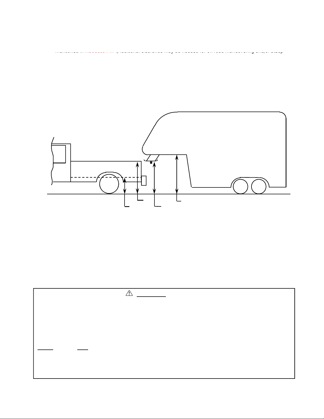
8. Hitch height determination:
mentioned in
instruction #7
(Additional clearance may be needed for off road maneuvering and/or steep
D –
C + 2 > 6 as noted in
instruction #7
A
•
Block in front of and behind all trailer tires
With trailer leveled and on level ground measure from the ground to the king pin box, Dimension “A” in Fig. 7.
Secondly, measure from the height of the inside of the truck bed to the ground, Dimension “B” in Fig. 7.
Dimensions “C” and “D” in Fig. 7 can be used to determine the amount of clearance over the side rails, as
inclines while turning).
The 2” value is an estimate of suspension compression due to king pin weight of the trailer. This
compression could range between 1”-5” depending on the truck being used and the trailer being towed.
Hitch Height = A – B + 2”
”
”
.
C
B
D
*MEASURED WITH TRAILER LEVEL,
ON LEVEL GROUND
FIG. 7
9. If a lube plate is to be used with a Elite Series Fifth Wheel it must be at least 12” in diameter. Cequent
Performance Products , Inc. offers this optional lube plate as part # 83001
WARNING:
•Connection for trailer wiring must be located at the side of the truck bed between the driver’s
seat and the rear wheel to prevent operators from working between the truck and trailer.
•Avoid putting any part of your body under the trailer or between the truck and trailer.
Unexpected or accidental movement of the truck or the trailer can cause serious injury or death
•If you must place any part of your body under the trailer or between the truck and trailer you
MUST
perform ALL of the following steps:
•Check that the truck transmission is in park
•Check that the emergency brake is on
•Check that the trailer landing gear are resting on firm ground
30144N– 05JUL10A PCN13292 ©2010 CEQUENT PERFORMANCE PRODUCTS, INC. Litho in USA 4
For Kit 30144
Page 5
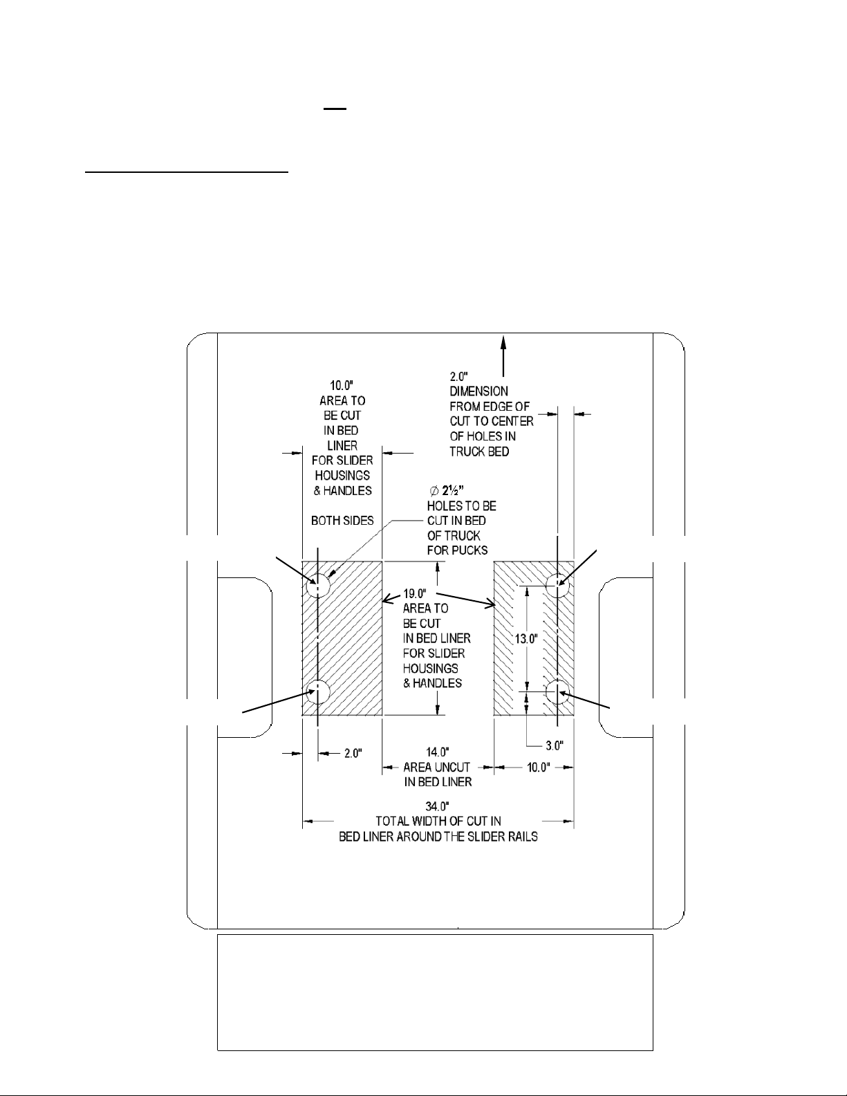
If your truck is equipped with a plastic bed liner, t hen cutting or removal of the plastic bed liner will be
skip to page 6 for the rest of the
Elite Series
FIFTH WHEEL SLIDER HITCH assembly
Center of hole
Center of hole
Figure 8
TAILGATE
necessary for the proper installation and operation of the
Elite Series FIFTH WHEEL SLIDER HITCH.
Refer to the “Plastic Bed Liner Instructions” portion on this page for complete instructions on where to cut
your plastic bed liner. If your truck is not
equipped with a plastic bed liner or if it has a spray in bed
liner, than you should use the instructions provided in the mounting kit for your specific truck and
.
Plastic Bed Liner Instructions:
1. Follow the mounting kit instructions for your specific vehicle.
2. Measure and mark the distances provided in Figure 8 for the correct areas to be cut out of your plastic bed
liner.
3. Remove the plastic bed liner from your truck and cut out the marked areas with a saw or cutting device of
your choice.
4. Reinstall the plastic bed liner.
5. Continue the rest of the
Elite Series FIFTH WHEEL SLIDER HITCH assembly.
Front of Truck
Center of hole
30144N– 05JUL10A PCN13292 ©2010 CEQUENT PERFORMANCE PRODUCTS, INC. Litho in USA 5
For Kit 30144
Center of hole
Page 6
ELITE SERIES FIFTH WHEEL ASSEMBLY
200 lb
White Lithi
component terminology
d
17.00”
instructions for your specific vehicle
TOOLS
15/16" Socket & Open End Wrench Safety Glasses
-ft Torque Wrench
3/4” & 1-1/2” Box or End Wrenches 9/16” Socket or Open End Wrench
3/4” Socket 7/16” Socket or Open End Wrench
Tape Measure
1. Check all the boxes for all the components
listed in Figure 1 and become familiar with
.
2. Loosely assemble the two slider assemblies
to the center section using 5/8-11 bolts and
lock washers
NOTE A: Hole positions used in assembly
will need to be made based on the head
height measurements taken previously,
calculated height closest to one of the
following height dimensions: 15.75” (2
holes down), 17.0” (3rdholes down),
18.25” (bottom holes).
DO NOT USE THE TOP HOLE.
See Figure 9.
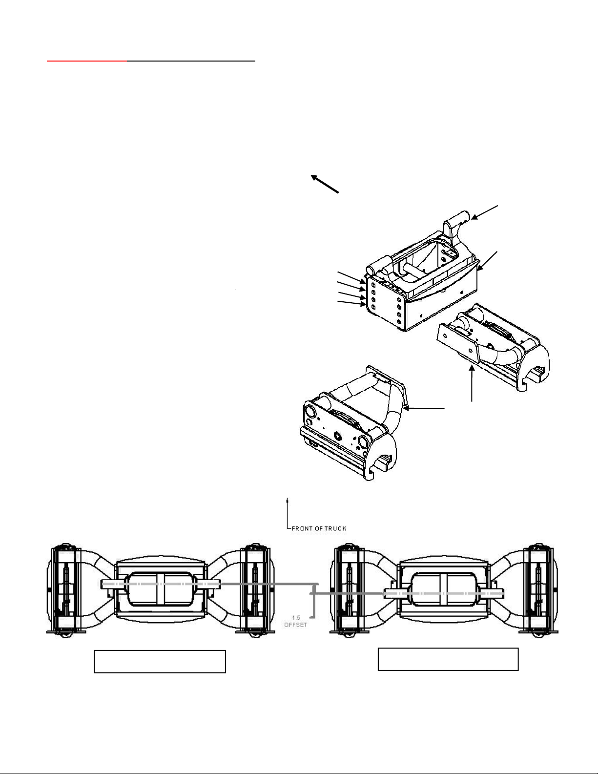
NOTE B: The ears on the center section
should be offset forward, if clearances allow.
See Figure 10. See mounting rail installation
3. Tighten 5/8” bolts in the center section to
170 ft-lbs.
n
.
Front of Truck
Hitch Height
DO NOT USE
15.75”
18.25”
um Grease & Wheel Grease
Ears
Center Section
Slider Assemblies
FORWARD OFFSET
30144N– 05JUL10A PCN13292 ©2010 CEQUENT PERFORMANCE PRODUCTS, INC. Litho in USA 6
For Kit 30144
Figure 9
REARWARD OFFSET
Figure 10
Page 7

4. Assemble the slider handle and the connector tube, minus the cotter pins. The cotter pin holes should all be
)
)
g&
py(
Slider Assembly Handle
Jaw Mechanism
Jaw Mechanism
on the same sides. See Figure 11a. Make sure the lock cams inside the slider assemblies are orientated in
the same direction, towards the front of the truck. See Figure 11b. If not, pull up on the “jaw” mechanism
and rotate them until they do. Slide the slider handle assembly through the driver’s side slider assembly.
The slider handle must be in the same orientation as the lock cams in the slider assembly (handle points
towards front of truck
pins should go into the holes that are nearest the slider assemblies). See Figure 11d. The indents on both
slider assemblies must be aligned to each other and also aligned to the holes in the slider handle and
connector tube. See Figure 11d. Do not put slider handle grip on slider handle yet.
. See Figure 11b & 11c. Insert the cotter pins into the slider handle assembly (cotter
Cotter pins
Cotter Pin Holes
Figure 11a
FRONT OF TRUCK
“
”
Lock Cam
Must point towards
front of truck
Driver’s Side Slider Assembly cut away view
Figure 11b
FRONT OF TRUCK
Slider Handle
Assembly
Figure 11d
FRONT OF TRUCK
Passenger Side Slider Assembly cut away view
“
”
Lock Cam
Must point towards
front of truck
30144N– 05JUL10A PCN13292 ©2010 CEQUENT PERFORMANCE PRODUCTS, INC. Litho in USA 7
For Kit 30144
Figure 11c
Page 8

5. Lube all 4 Anchor Bushing with white
1” J
Anchor Assemblies
Anchor Bushing Assembly
lithium grease. Do this by spraying or
manually applying the grease to the inside
of the Anchor Bushing. See Figure 12.
Lube Locations
White Lithium Grease
Figure 12
6. Loosely assemble the four anchor bushings to the slider rails using the tab washers and 1” jam nuts.
See Figures 13a & 13b.
Slider Rail
am Nut
Tab Washer
Anchor Bushing
Anchor Bushing
Figure 13a
7. Place the slider rails as per Figure 14 into the mounting pucks previously installed in the truck (See Elite
Series
Mounting Kit Instructions).
Figure 13b
Front of Truck
30144N– 05JUL10A PCN13292 ©2010 CEQUENT PERFORMANCE PRODUCTS, INC. Litho in USA 8
For Kit 30144
Pucks
Figure 14
Page 9

8. Measure from the bottom of the seam in the passenger side roller housing to the bottom of the seam in the
Driver s Side
Sid
g
the locations in
Figure 16
These 2 diagonal
q
y
q
y
driver’s side roller housing on the front side of the
FIFTH WHEEL Slider Hitch. Measure from the inside
to the outside of the cut out in the face plate on the rear side of the FIFTH WHEEL Slider Hitch.
Note which measurement is smaller. See Figure 15.
Passenger
e
MEASURE FROM THE BOTTOM OF
THE SEAM IN THE ROLLER HOUSING
MEASURE FROM THE INSIDE OF THE CUT OUT TO
THE OUTSIDE OF THE CUT OUT IN THE FACE PLATES.
Driver’s Side
9. Measure the distance between the 2 slider rail
assemblies that are in the truck bed at the
“Center line Dimension” in Figure 16. Adjust
the slider rail assemblies so that they measure
the same distance apart as the smaller
dimension measured in Step 8. Measure
diagonally across the slider rail assemblies at
measurements must be equal to ensure that
the rails are squarely lined up in the truck bed.
.
Figure 15
’
Passenger Side
Front of Truck
Note: Due to the heavy duty nature of the FIFTH
30144N– 05JUL10A PCN13292 ©2010 CEQUENT PERFORMANCE PRODUCTS, INC. Litho in USA 9
For Kit 30144
WHEEL Slider Hitch, the assembly may
not slide by hand when installed,
especially if slider rails are not securely
installed to insure they are parallel and
square.
Rails should be installed so that the
centerline measurement of the slider rail
assemblies are the same as the smaller
measurement at the bottom of the seam
in the roller housing performed in Step 8.
Rails should also be s
uare in the truck
bed. The diagonal measurements
performed in Step 9 should be the same.
Diagonal Measurements
Centerline Measurement
Figure 16
Slider Rail Assembl
Driver’s Side
Passenger Side
Page 10

10. Once the slider rail assemblies are square to each other, snug tight (no vertical play in anchor bushing assembly) all
Box End Wrench
½ times
) counter clockwise until the hole and slot re
align. The 3/16 cotter pin can now be inserted into the hole
Anchor Bushing
Hole in Anchor Tee Pin
four 1” jam nuts inside the slider rails using a 1-1/2” box end wrench as it sits in the pucks in the bed of the truck.
Finish tightening each jam nut by turning the nut 1/4 turn more to achieve the required torque. See Figure 17.
Measure the slider rails after the 1” jam nuts are torqued, to be sure that they remained square and equal to the
smaller dimension measured in Step 8. while tightening. If they are not square and equal to the smaller
dimension measured in Step 8 , then loosen the 1” jam nuts and repeat Steps 9 & 10 until they are square.
Slider Rail Assembly
Anchor Bushing Assembly
Figure 17
11. Remove the rails from the truck bed and prepare for installing the Anchor Tee Pins, Anchor Handles and the 3/16”
cotter pins. Install the Anchor Tee Pin by inserting it up through the Anchor bushing and threading it into the Anchor
Handle. See Figure 18a. Each slider rail gets one of each anchor handle (Anchor Handle “A” & Anchor Handle “B”).
See Figure 19 for correct handle orientation. The Anchor Tee Pin should be threaded as far as it can go into the
Anchor Handle. The hole in the Anchor Tee Pin will probably not line up with the slot in the Anchor Handle nut at this
point and should be turned back slowly until they are inline. Once aligned, rotate the Anchor Tee Pin 540 degrees (1
Once the 3/16” cotter pin is in place, pry open the ends and bend them back on themselves to secure. At this point,
also bend up (1) tab on each tab washer that best matches up with a flat on each jam nut. This is to keep jam nuts
from working loose over time. See Figures 18a, 18b & 18c.
Cotter Pin
Anchor Handle “A” Shown
Anchor Handle
Jam Nut
Anchor
Tee Pin
Anchor Tee Pin
Figure 18a
”
Anchor Assembly
.
Figure 18b
Slot in Anchor Handle nut
Anchor Handle nut
Anchor Handle
30144N– 05JUL10A PCN13292 ©2010 CEQUENT PERFORMANCE PRODUCTS, INC. Litho in USA 10
For Kit 30144
1” Jam Nut
Tab Washer with (1) tab bent
up against flat of Jam Nut
Figure 18c
Page 11

12. When properly installed, all the Anchor Handles should be parallel to the Slider Rail Assembly when locked. The
Anchor Handle A
g
Pi
t
be installed th
Anchor Handles are Unlocked when rotated 90 degrees (perpendicular to the Slider Rail Assembly). See Figure
19. The stamped wording on the handles should always face upward.
WARNING:
Failure to properly install handles could result in tow vehicle damage.
Locked: Anchor Handles
are parallel to the slider rail.
Anchor Handle “B”
Locked Position
Front of Truck
Lynch Pin through
holes in Anchor Handles
See sketch below
Unlocked: Anchor Handles are
90 degrees to the slider rail.
“
”
Unlocked Position
Anchor Handle “A”
Locked Position
30144N– 05JUL10A PCN13292 ©2010 CEQUENT PERFORMANCE PRODUCTS, INC. Litho in USA 11
For Kit 30144
Slider Rail Assembly
Figure 19
Bottom of Hitch Shown
WARNING:
To prevent serious damage to
truck and/or persons both Lynch
ns Mus
the holes in the Anchor Handles
for the hitch to be properly
locked.
rough
Anchor Handle “B”
Unlocked Position
Slider Rail Assembly
Install Lynch Pin through
holes in Anchor Handles to lock
Page 12

13. Grease Lock Arms, Lock Cams, Springs, and Rollers in both Slider Assemblies. Grease the Guide
Roller
Grease to both rails
Detail
Slots in the Slider Rails. Apply white lithium grease to entire rail of both Slider Rails before use. See
Figure 20a & 20b.
Grease
Roller
Grease
Lock Arm & Spring
Figure 20a Apply white lithium
Grease
Guide Slot
Grease
Lock Cam
Before use.
See label below
Grease
Grease
Guide Slots
30144N– 05JUL10A PCN13292 ©2010 CEQUENT PERFORMANCE PRODUCTS, INC. Litho in USA 12
For Kit 30144
See Enlarged
Figure 20b
Page 13

14. Install the torsion springs, tube spacers, fender washers and bolt. See Figure 21 . Left hand and Right hand torsion
Front of Truck
¼ Fender Washer
springs need to be installed into the center section so that the coil is facing the rear of the truck and wide hook sits
over casting as shown in Figure 21. Tighten Bolt.
Torsion Spring
Right hand shown
Tube Spacer
(Torsion Spring)
Figure 21
”
Bolt
Lube 6 Places
15. Lube center section with lithium
grease as shown in Figure 22.
Figure 22
16. Reinstall the Slider Rail Assemblies back into the truck bed as shown in Figure 23. Rotate the Anchor handles
into the locked position and attach the lynch pins. See Figures 1, 19 & 23
17. Align the slider assemblies up to the slider rails attached in the truck. Ensure that both Slider Rails have
been coated with White Lithium Grease (See figure 20b). See Figure 23.
Note: slot location on Slider Assembly
Slider Assemblies
Front of Truck
Slider Rail Assembly
must be Orientated
as Shown for the
Proper Installation
of the Hitch
Slider Rail Assembly
Lynch Pin installed in
lock Anchor Handles
30144N– 05JUL10A PCN13292 ©2010 CEQUENT PERFORMANCE PRODUCTS, INC. Litho in USA 13
For Kit 30144
Slider Handle
in locked towing position
pointed towards front of truck
Slider Assembly
Driver’s Side
Connector tube
Figure 23
Slider Assembly
Passenger Side
Page 14

18. Slide the entire slider assembly onto the slider
lid
lid
ith all handl
move freely in the
rails. See Figure 24. This is accomplished by
rotating the slider handle into the unlocked
position, See Figure 25. It may be necessary
to lift the “Jaw” Mechanism by hand when
starting the s
See Figure 26.
19. Install 1/2” bolts and 1/2” lock nuts onto both
slider assemblies. See Figures 1, 25, & 26.
Lock nut must be installed to the outside of
the system. A maximum of 3 threads MUST
be showing. Do not torque. See lock nut
detail below.
20. Rotate the handles in the anchor assemblies
to the unlocked position and lift the entire
slider assembly and slider rails out of the
pucks. This is a precautionary measure to
insure that the hitch is assembled
correctly. If your hitch does not lift out of
the pucks repeat steps 7-11 on page 8-10.
21. Replace the entire slider assembly and slider
rails into pucks w
position. Rotate the handles to the locked
position, and place lynch pins through anchor
handle holes.
See Figure 19.
er assembly on the s
es in unlocked
er rail.
Front of Truck
Figure 24
Slider Handle in
Unlocked Position
Slider Assembly in
Towing Position
“Jaw” Mechanism
½” Lock Nut –
Nut MUST be installed
To the outside of system for
System to work properly..
Figure 26
Figure 25
1/2”
Bolt
1/2” LockNut
See detail below
Lock nut to be installed
to the OUTSIDE of the
slider. DO NOT
TORQUE. Bolt MUST
system.
30144N– 05JUL10A PCN13292 ©2010 CEQUENT PERFORMANCE PRODUCTS, INC. Litho in USA 14
For Kit 30144
Page 15

22. Place and pin head onto center section. See Figures 27 & 28.
y, g
yg g
g
y
can easily be seen through the
23. Add Handle Tube, Grip Handle Tube, Carriage Bolts, washers & nuts. See Figure 27. Torque 3/8” hardware to
35 ft-lbs.
24. Lube jaw and skid plate (If no lube plate is being used). See Figure 28. The jaw pin comes greased from the
factor
smooth jaw operation.
rease fitting on top of head. See Figure 28. Grease should be added every 6 months to insure
3/8” Carriage Bolts
3/8” Washers
3/8” Nuts
Grip to Handle Tube
Handle Tube
WARNING:
Tilting the Fifth Wheel head can
crush and cut. Keep hands and
fingers clear from this area at all
times (including placement or
removal of the head.)
Sight Hole
Lube skid Plate
(With no Lube Plate
Lube Jaw
Figure 27
Front of Truck
)
Grease Fitting
Figure 28
30144N– 05JUL10A PCN13292 ©2010 CEQUENT PERFORMANCE PRODUCTS, INC. Litho in USA 15
For Kit 30144
WARNING:
To prevent tilting head
detachment and /or separation,
you must make sure that the
spring retaining clips are installed
onto the 1/2” pull pins before
towing. The spring retaining clips
site holes in the top of the head.
Pull Pin
Retaining Clip
Page 16

25. Use the supplied screws to install the plastic covers by sliding it around the slider handle through the hole in the
Lock Pi
Slider Assembly
Figure 31
plastic cover. See Figures 1 & 29. The plastic cover with the larger label should be placed on the driver’s side of
the truck. Install the lock pin and nylon lanyard using the screws provided. Install the slider handle grip onto the
slider handle. See Figures 29. The lock pin is a device that keeps the “Jaw” mechanism from opening.
Therefore it must be installed and used anytime the hitch is in use, see Figure 30, except when the sliding
mechanisms needs to be in operation for maneuvering the hitch to and from the maneuvering position.
See Figure 31.
Screws
n
Plastic Cover
Slider Handle
Grip
Figure 29
Driver’s Side Shown
Slider Handle
Front of Truck
Front of Truck
Large Label
Nylon Lanyard
Plastic
Hole in Plastic Cover
Lock Pin
Slider Handle
30144N– 05JUL10A PCN13292 ©2010 CEQUENT PERFORMANCE PRODUCTS, INC. Litho in USA 16
For Kit 30144
Slider Rail
Figure 30
Cut-Away View Shown
Hitch in Maneuvering Position
Page 17

NOTES
state. In the event of a problem with warranty service or performance, you may be able to go to a small
SEVEN YEAR LIMITED WARRANTY
Cequent Performance Products, Inc. warrants its Elite Series Fifth Wheel Hitches from date of purchase
against defects in material and workmanship under normal use and service, ordinary wear and tear
excepted, for 7 years of ownership to the original consumer purchase r when a Cequent Performance
Products, Inc. mounting kit is used.
Cequent Performance Products, Inc. will replace FREE OF CHARGE any part which proves defective in
material or workmanship when presented to any Cequent Performance Products, Inc. dealer, Cequent
Performance Products, Inc. Warehouse or returned to factory. TRANSPORTATION CHARGES
PREPAID, at the address below. THIS WARRANTY IS LIMITED TO DEFECTIVE PARTS
REPLACEMENT ONLY. LABOR CHARGES AND/OR DAMAGE INCURRED IN INSTALLATION OR
REPLACEMENT AS WELL AS INCIDENTAL AND CONSEQUENTIAL DAMAGES CONNECTED
THEREWITH ARE EXCLUDED.
Some states do not allow the exclusion or limitation of incidental or consequential damages, so the above
limitation or exclusion may not apply to you.
Any damage to the Fifth Wheel Hitch as a result of misuse, abuse, neglect, accident, improper installation,
or any use violative of instructions furnished by us, WILL VOID THE WARRANTY.
This warranty gives you specific legal rights, and you may also have other rights which vary from state to
claims court, or a federal district court.
Cequent Performance Products, Inc.
47774 Anchor Ct. West
Plymouth, MI. 48170
30144N– 05JUL10A PCN13292 ©2010 CEQUENT PERFORMANCE PRODUCTS, INC. Litho in USA 17
For Kit 30144
 Loading...