

Page 1
INSTRUCTION & OPERATION MANUAL
You can take it with you.
20K - Fifth Wheel Hitch
DEALER/INSTALLER:
(1) Provide this Manual to end user.
(2) Physically demonstrate hitching and unhitching
procedures in this Manual to end user.
(3) Have end user demonstrate that he/she
understands procedures.
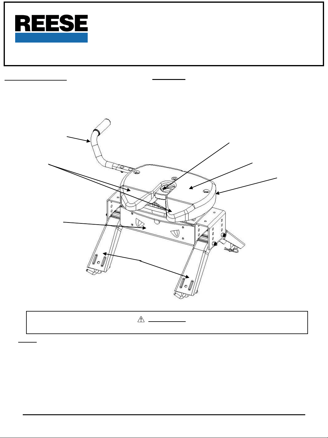
HANDLE
RAMP
END USER:
(1) Read and follow this Manual every time you use hitch.
(2) Save this Manual and Hitch Warning Hang Tag for future reference.
(3) Pass on copies of Manual and Hitch Warning Hang Tag to any other
user or owner of hitch.
(4) Never remove hitch warning decals as shown on the cover of this
manual. If damaged, contact Cequent Performance Products (1-
800-632-3290) for free replacement.
JAW TO HOLD
KING PIN
SKID PLATE
HEAD
ASSEMBLY
CENTER SECTION
SIDE BRACKETS
WARNING:
Failure to follow all of these instructions may result in death or serious injury
INDEX
1. ASSEMBLY INSTRUCTIONS
2. BEFORE EACH TRIP P. 2
3. HITCHING PROCEDURE P. 3
4. PULL TEST P. 6
5. UNHITCHING PROCEDURE P. 6
6. MAINTENANCE P. 7
7. FIVE YEAR LIMITED WARRANTY P. 9
8. APPENDIX A (Guidelines for matching hitch, truck, and trailer) P. 10
9. APPENDIX B (Guideline for center section orientation) P. 14
For Installation Assistance or Technical Help, Call 1-888-521-0510
30081N-7 July10 F PCN13787 ©2010 CEQUENT PERFORMANCE PRODUCTS, INC LITHO IN USA
FOR KITS: 30081, 40261 & 50181
Page 2
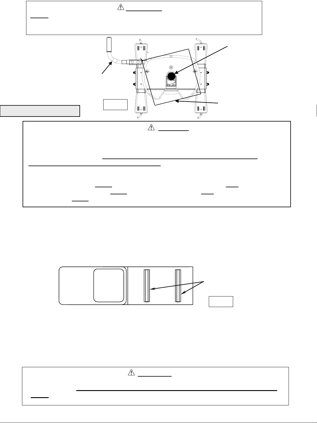
WARNING:
Do Not use this hitch for towing a trailer with a pin box that could come into contact with
or interfere with the latch for the hitch handle when turning! (See Fig. A) If the pin box
contacts the hitch handle or its latch when turning, the trailer may become unhitched.
KING PIN
LATCH
Fig. A
ASSEMBLY INSTRUCTIONS
BOTTOM OF PIN BOX
WARNING:
Connection for trailer wiring should be in the side of the truck bed between the driver’s
seat and the wheel well for the back truck axle
Installation of connection rearward of the wheel well may result in user placing body
between truck and trailer. WHENEVER POSSIBLE, AVOID PUTTING BODY UNDER
TRAILER OR BETWEEN TRUCK AND TRAILER!
If you need to place any part of your body under trailer or between truck and trailer:
All trailer tires MUST be blocked in front and behind each tire AND
Trailer landing gear MUST be resting on firm ground AND
Truck MUST be stationary, in park, with emergency brake on!
1. Reference Fig. 11 on page 8.
2. 5th Wheel Kit is contained in three cartons. Unpack and become familiar with parts on parts list. Base rails, brackets and
hardware are in separate kit (part no. 30035) with separate Installation Instructions for Fifth Wheel Rail Mounting Kit.
3. Place two base rails across bed of truck (See Fig. B). Select one side bracket and place tabs through the centermost
rectangular slot in the base rails. Slip long pull pins through holes in base rails. Repeat. Secure pull pins with spring retaining
clips.
BASERAILS
Fig. B
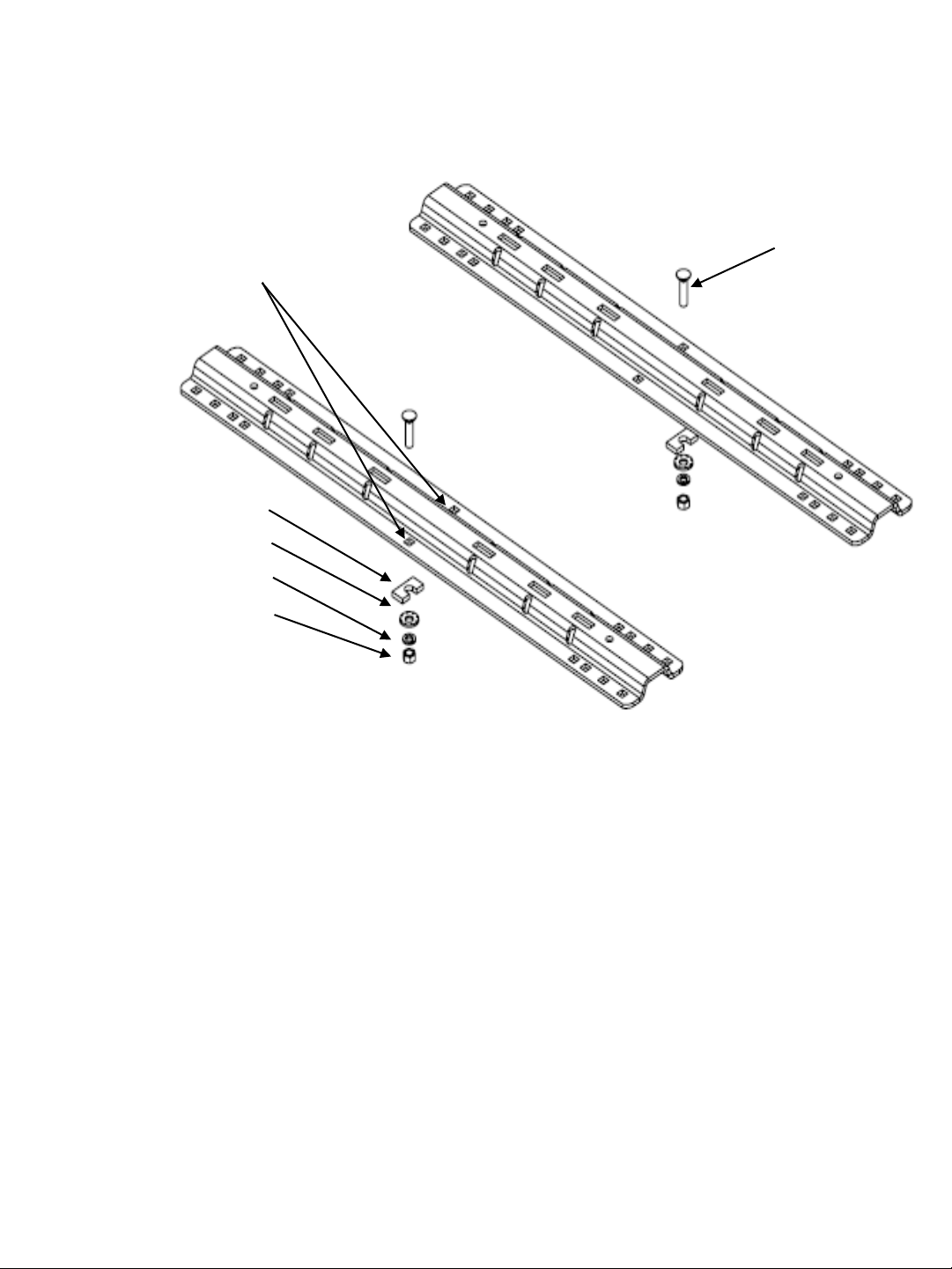
4. Select 20K Center Section and install on leg aligning holes for hitch height desired. (Lowest position 13" highest 17").
Install four 1/2-13 x 4.5" Hex bolts, (with heads toward inside as shown) and lock nuts. (See Appendix B for center
section orientation)
5. Torque 1/2" nuts to 75 lb. ft.
6. Install base rails and mounting brackets as described in "Installation Instructions for 5th Wheel Rail Mounting Kit,” Part #
30035.
WARNING
Base rails must be bolted through the floor of the pickup to the brackets that attach to
the truck frame. DO NOT INSTALL BY FASTENING TO THE FLOOR OF THE PICKUP BOX
ONLY. The floor alone is not strong enough to carry the loads imposed by the trailer.
30081N-7 July10 F PCN13787 ©2010 CEQUENT PERFORMANCE PRODUCTS, INC LITHO IN USA
FOR KITS: 30081, 40261 & 50181
Page 3
SUPPLEMENT TO 30095N
INSTALL BOLT IN EITHER POSITION WHICHEVER
IS CLOSER TO UNDER BED SUPPORT
SPACER (30)
SERRATED WASHER (31)
LOCK WASHER (32)
½” CARRIAGE BOLT (29)
½” HEX NUT (33)
ADDITIONAL MOUNTING INSTRUCTIONS:
Install base rails as instructed in base rail instructions. The instruction below is for the
addition of the 2 center bolts for applications using 30095.
1. Place base rails in accordance with base rail mounting instructions.
2. BEFORE DRILLING ANY HOLES, CHECK FOR CLEARANCE AROUND THE GAS TANK.
3. Using the center hole in the base rail as a guide, drill a ½” hole through the truck bed.
4. Insert ½” carriage bolt (29) into the hole. Install ½” serrated washer (31), ½” lock washer (32) and ½”
nut (33).
5. Insert spacer (30) between the truck bed and the base rail. It will go in between at the corrugation of the
bed. To keep bed from crushing when the bolt is tightened.
6. Repeat for the other base rail.
7. Torque the ½” nuts to 75 ft/lbs.
30081N-7 July10 F PCN13787 ©2010 CEQUENT PERFORMANCE PRODUCTS, INC LITHO IN USA
FOR KITS: 30081, 40261 & 50181
3
Page 4
GUIDELINES FOR MATCHING HITCH TRUCK AND TRAILER
If preparing to tow a 5th wheel trailer which you have not rating checked previously, please
consult Appendix A of 5th Wheel Kit assembly instructions.
BEFORE EACH TRIP:
1.Lubricate skid plate surface of the hitch and pivot pin grease fitting (see Figure on cover of Manual) with automotive type
chassis grease or use a plastic lube plate to provide a lubricated surface. Use lithium grease to lubricate pivot points of
moving parts within the hitch.
2. Plastic lube plates (Performance Products No. 83001/40001) can be used to avoid messy grease. The plastic lube plate
must not exceed 3/16 of an inch in thickness to ensure hitch will operate properly. Lube plates must be 12 inches in
diameter or larger to properly distribute king pin weight.
3. Before each trip or maneuver, operate the handle and check that the jaw opens and closes freely.
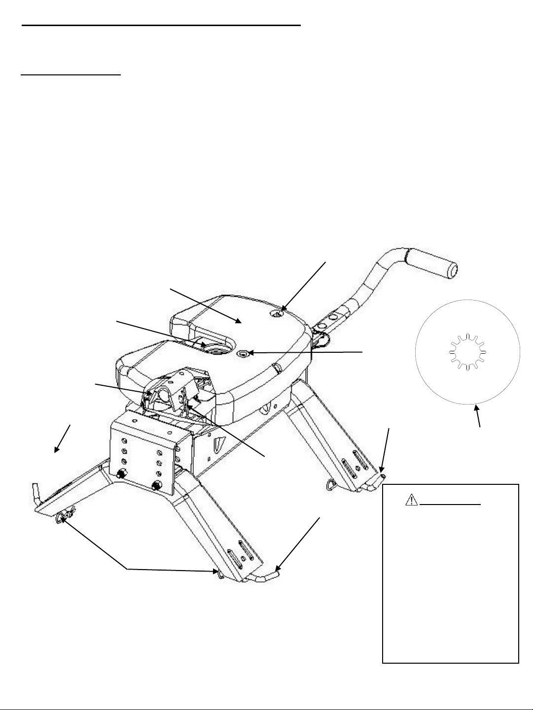
4. See that all hitch pull pins (#7 (P/N 30434) & #12 (P/N 110974), Figure 11) are in place and the spring retaining clips (#4,
Figure 11) are installed (Figure 1). Note that hitch pull pins used to attach the head assembly to the center section for the 5th
Wheel Kit Hitch are 90 degree bent pins and if replacements are needed, please contact Customer Service at (800) 632-
3290. Check that all four anchor assembly pins are pinned and have the retaining clips attached.
Sight Hole
Lube Skid Plate
(With No Lube Plate)
Lube Jaw
Pull Pin 90°
Pull Pin
Retaining Clip
Retaining Clip
Figure 1 : Pin and Clip (Skid Plate cut away view)
Pull Pin
Grease Fitting
Pull Pin
Lube Plate
(Optional)
WARNING:
To prevent tilting head
detachment and or
separation of hitch you must
make sure that the anchor
assemblies are properly
installed and pinned, and
the spring retaining clip is
properly installed onto the
½” pull pin before towing.
The spring retaining clip can
easily be seen through the
site holes in the top of the
head.
30081N-7 July10 F PCN13787 ©2010 CEQUENT PERFORMANCE PRODUCTS, INC LITHO IN USA
FOR KITS: 30081, 40261 & 50181
Page 5
HITCHING PROCEDURE:
IMPORTANT: YOU ARE RESPONSIBLE FOR SAFE HITCHING AND UNHITCHING OPERATIONS. DO NOT RELY ON
OTHERS TO PERFORM THESE DUTIES. YOU MUST PERSONALLY MAKE SURE THE FOLLOWING
STEPS ARE PERFORMED IN THE FOLLOWING ORDER!
WARNING:
FAILURE TO FOLLOW THESE INSTRUCTIONS MAY RESULT IN DEATH OR SERIOUS INJURY.
1. Place blocks (sometimes called “chocks”) firmly against front and rear of each trailer wheel to prevent any possible
forward or rearward motion. DO NOT REMOVE BLOCKS UNTIL EACH OF THE FOLLOWING STEPS AND THE
PULL TEST HAVE BEEN COMPLETED. Lower tailgate if necessary. Clearance of the lowered tailgate to the trailer needs
to be monitored during hookups as some manufacturer combinations of truck and trailer have little or no clearance.
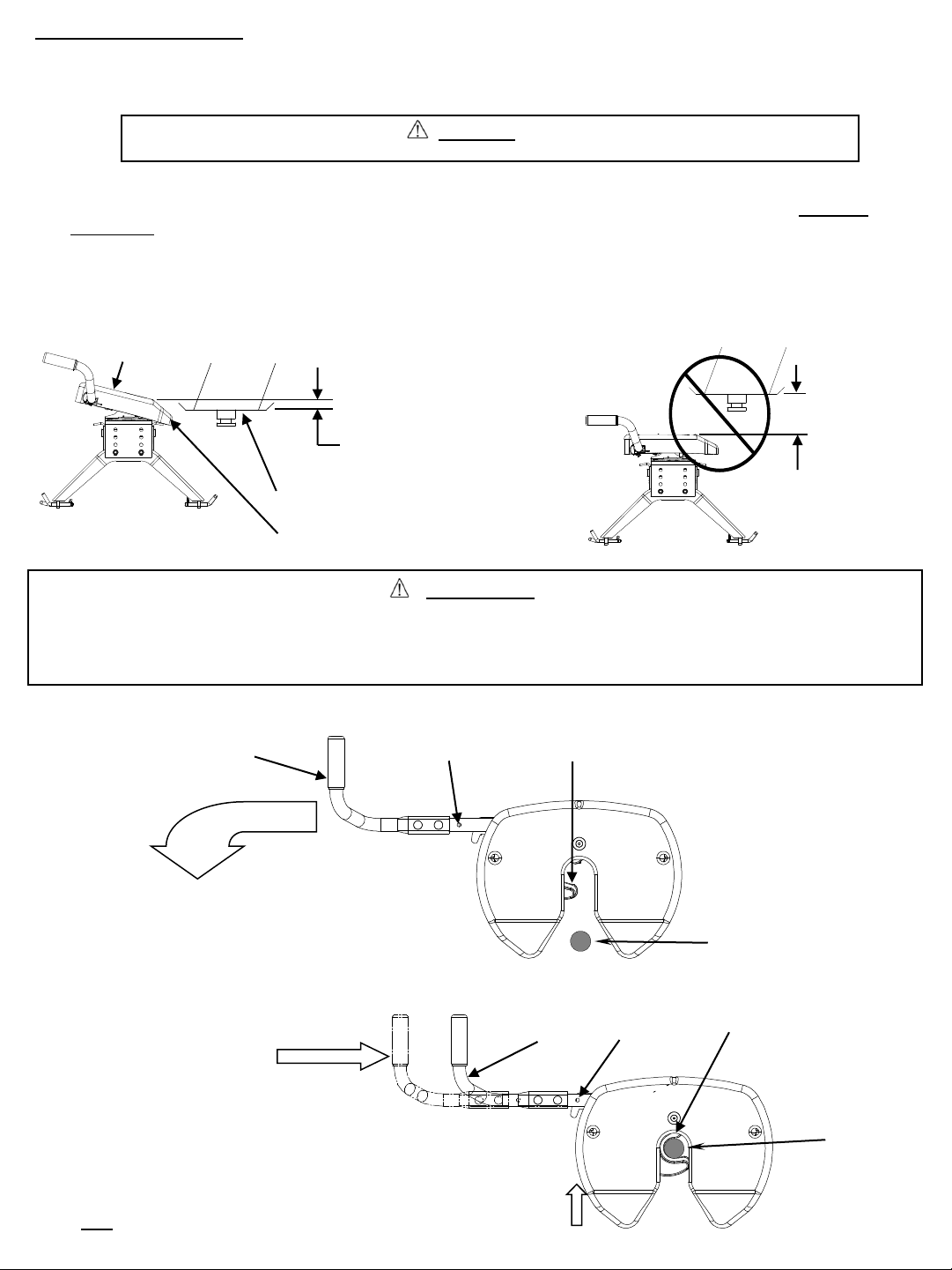
2. Using trailer jacks, adjust trailer height following the directions in the trailer manual so that bottom of trailer pin box (“A” in
Figure 2) is ½ to 1 inch below skid plate (See “B” in Figure 2). During the hitching maneuver, the bottom of the trailer pin
box should come in contact with skid plate ramp (“C” in Figure 2).
Hitch Skid Plate (B)
Figure 2
CORRECT
Bottom of Pin Box (A)
1/2 To 1 Inch Below
Hitch Skid Plate (B)
Bottom of Pin Box (A)
Skid Plate Ramp (C)
Figure 3
WRONG
Bottom of
Pin
Box Above
Hitch Skid
Plate
WARNING:
Failure to follow this instruction may result in king pin being too high and coming to rest on top of the closed jaw
or not completely inside jaw. (See Figure 6 & 7). This could result in trailer separating from hitch. Trailer
separation may result in death or serious injury if anyone is under the trailer or between truck and trailer when
separation occurs.
3. Remove bail pin from bail pin hole (see Figure 4). Then pull handle out and rearward to hold open
NOTE: Hitch jaw must be in the open position for king pin to enter the hitch.
Handle
Pull handle out
and latch to the
rear to open
hitch jaw
4. With handle in the open position (See Figure 4), back truck slowly into trailer. As king pin
completely enters head, jaw will spring closed around king pin and handle will return to the closed
position. If the handle does not return to the
closed position, then
try to push the handle back to the
closed position. If handle does
not return to the closed position
then move the truck slightly forward
or rearward until the handle returns
to the closed position. (See Figure 5)
Bail Pin Hole
Figure 4
Hitch Jaw (Shown in open position)
King pin
Handle
Bail Pin Hole
Hitch Jaw
King pin
5. Use only the method described above for hitching.
30081N-7 July10 F PCN13787 ©2010 CEQUENT PERFORMANCE PRODUCTS, INC LITHO IN USA
FOR KITS: 30081, 40261 & 50181
Figure 5
Page 6

6. With all trailer wheels still firmly blocked, landing gear still resting on firm ground and supporting trailer weight, and
truck stationary and in park with emergency brake on: visually check that bottom of pin box is resting on top of the
hitch. THERE SHOULD BE NO SPACE BETWEEN THESE SURFACES (see Figure 6). If space exists, (see
Figure 7) trailer has not been properly hitched. DO NOT TOW! Instead, repeat above steps until trailer is properly
hitched. DO NOT PLACE BODY UNDER TRAILER TO PERFORM THIS INSPECTION!
No Space
GAP
Figure 6
CORRECT
7. Place bail pin through bail pin holes in the handle and the base plate to make sure the hitch jaw is locked closed. IF
FLAG BLOCKS HOLE FOR BAIL PIN, TRAILER HAS NOT BEEN PROPERLY CONNECTED TO HITCH. DO NOT
TOW! Repeat above steps until trailer is properly hitched. (see Figure 8)
Bail pin placement
Bail Pin
Handle
Hole for bail pin
Figure 7
WRONG
High Pin
King Pin
Flag
Base plate
Figure 8
8. With:
•All trailer wheels still firmly blocked in front and behind each tire, and
•Truck stationary with the emergency brake on, and
•Trailer landing gear still resting on firm ground and supporting trailer weight; and
Connect electrical cable between truck and trailer, connect breakaway switch cable from pin box to a permanent
part of truck, and raise tailgate of truck. Do not tow trailer until the Pull Test has been successfully completed.
30081N-7 July10 F PCN13787 ©2010 CEQUENT PERFORMANCE PRODUCTS, INC LITHO IN USA
FOR KITS: 30081, 40261 & 50181
Jaw closed
Page 7

WARNING:
Do not attempt to hitch by using trailer jacks to lower trailer and king pin. This could result in king pin
coming to rest on top of skid plate instead of within hitch opening where jaws are located. King pin could
slide off hitch and trailer could drop, resulting in death or serious injury (see Figure 9).
Figure 9
WRONG
WARNING:
Connection for trailer wiring should be in the side of the truck bed between the driver’s
seat and the wheel well for the back truck axle
Installation of connection rearward of the wheel well may result in user placing body
between truck and trailer. WHENEVER POSSIBLE, AVOID PUTTING BODY UNDER TRAILER
OR BETWEEN TRUCK AND TRAILER!
If you need to place any part of your body under trailer or between truck and trailer:
All trailer tires MUST be blocked in front and behind each tire AND
Trailer landing gear MUST be resting on firm ground AND
Truck MUST be stationary, in park, with emergency brake on!
PULL TEST
WARNING:
Failure to perform pull test may result in death or serious injury
1. With all trailer wheels still firmly blocked, and
2. Trailer landing gear still resting on firm ground and supporting trailer weight and,
3. Truck stationary and with emergency brake on:
4. Make sure no one is between truck and trailer, Return to cab of truck and release truck’s emergency brake. Apply trailer
brakes. Try to pull trailer slowly forward with the truck. If the trailer is properly hitched, the wheel blocks and trailer brakes
should keep the truck from moving forward.
NOTE: If trailer is not properly hitched, trailer will separate from hitch and truck will move forward leaving trailer behind. If
you followed all previous steps, the trailer will not drop or fall and you will easily be able to repeat the attachment
steps.
WARNING:
Failure to keep wheels blocked and landing gear down could result in trailer suddenly moving or
falling. This could result in death or serious injury!
5. After successfully performing above steps, fully raise trailer landing gear (see trailer manual).
6. Check and inspect all electrical circuits for proper operation. (Clearance lights, turn signals, stop lights, etc.).
7. Remove and store all trailer wheel blocks.
30081N-7 July10 F PCN13787 ©2010 CEQUENT PERFORMANCE PRODUCTS, INC LITHO IN USA
FOR KITS: 30081, 40261 & 50181
Page 8

UNHITCHING PROCEDURE:
PERFORM THE FOLLOWING IN THIS ORDER:
1. Make sure truck is in park with emergency brake on.
2. Place blocks firmly against front and rear of each trailer wheel to prevent any possible forward or rearward motion.
3. Using trailer jacks, lower trailer landing gear following the directions in the Trailer Manual until feet of landing gear are
resting on firm ground.
WARNING:
Trailers that are not stable or properly hitched can fall and cause death or serious injury!
To avoid death or serious injury:
• All trailer tires MUST be blocked in front and behind each tire AND
• Trailer landing gear MUST be resting on firm ground AND
• Truck MUST be stationary, in park, with emergency brake on!
4. Lower truck tail gate.
5. Disconnect power cable and breakaway switch cable between truck and trailer.
6. Remove bail pin from hole in handle.
7. Pull hitch handle out completely until it latches in open position so that king pin is no longer
securely grasped by hitch jaws (see Figure 4). Trailer is now free from hitch and truck. If handle does not pull out,
there is probably pressure against the jaw. To relieve this pressure, back the truck slightly or pull the truck slightly
forward. Reset truck emergency brake. Then pull hitch handle out completely until it latches in open position.
8. AFTER MAKING CERTAIN NO ONE IS STANDING BETWEEN TRUCK AND TRAILER OR IN FRONT OF TRUCK,
drive truck slowly away from trailer.
WARNING
Whenever possible, avoid putting body under trailer or between truck and trailer
If you need to place any part of our body under trailer or between truck and trailer:
All trailer tires MUST be blocked in front and behind each tire AND
Trailer landing gear MUST be resting on firm ground AND
Truck MUST be stationary, in park, with emergency brake on!
9. Hitch jaw will automatically close as the king pin is removed from the jaw.
10. KEEP WHEEL BLOCKS IN PLACE. This will keep trailer from moving unexpectedly
MAINTENANCE:
1. Recheck tightness of all hardware every 1000 miles of use. All 1/2” bolts have a torque specification of
75ft.lbs.
2. See “Before each trip” section in this manual.
3. Head assembly to center section should be lubed every 12 months with grease to keep assemblies
moving freely.
WARNING:
Tilting 5thWheel head can
crush and cut. Keep hands and
fingers clear from this area at
all times (including
placement/removal of head).
Figure 10 : Head Placement
30081N-7 July10 F PCN13787 ©2010 CEQUENT PERFORMANCE PRODUCTS, INC LITHO IN USA
FOR KITS: 30081, 40261 & 50181
Page 9

19
REF # QTY.
DESCRIPTION REF # QTY DESCRIPTION
1 1 18K HEAD ASSEMBLY 13 1 HANG TAG (P/N 110795)
2 1 18K CENTER SECTION 14 1 BAIL PIN WITH LANYARD (P/N 110896)
3 2 SIDE BRACKET (P/N 30834) 15 1 LABEL, PINCH POINT (P/N 110954)
4 6 RETAIN CLIP (P/N 55515) 16 1 LABEL, OPERATION WARNING (P/N 110793)
5 4 ½” X 4 1/2 “ BOLTS (P/N 01150018) 17 2 LABEL, RATING (P/N 113145)
6 4 ½” LOCK NUTS (P/N 3376) 18 1 HANDLE TUBE (P/N 110470)
7 4 ½” DIA LONG PULL PIN (P/N 30434) 19 1 HANDLE GRIP (P/N 07417)
8 2 ¼” X 20 – 1.75 HX HEAD BOLT (P/N 55256) 20 2 3/8 CARRIAGE BOLT (P/N 01246005)
9 2 TUBE SPACER (P/N 110898) 21 2 3/8 NUT (P/N 55052)
10 2 TORSION SPRING (P/N 110787 & 110788) 22 2 3/8 LOCK WASHER (P/N 01129006)
11 2 ¼” WASHER (P/N 55546)
12 2 1/2” PULL PIN 90° (P/N 110974)
20
14
1
18
22
21
9
8
10
11
12
6
2
5
3
7
4
3
Figure 11
30081N-7 July10 F PCN13787 ©2010 CEQUENT PERFORMANCE PRODUCTS, INC LITHO IN USA
FOR KITS: 30081, 40261 & 50181
Page 10

NOTES
FIVE YEAR LIMITED WARRANTY
Fifth Wheel Hitches
Cequent Performance Products warrants the 20K 5th Wheel Hitch from date of purchase against defects
in material and workmanship under normal use and service, ordinary wear and tear excepted, for 5 years
of ownership to the original consumer purchaser when a Cequent Performance Products mounting kit is
used.
Cequent Performance Products will replace FREE OF CHARGE any part which proves defective in
material or workmanship when presented to any Cequent Performance Products dealer, Cequent
Performance Products Warehouse or returned to factory. TRANSPORTATION CHARGES PREPAID, at
the address below. THIS WARRANTY IS LIMITED TO DEFECTIVE PARTS REPLACEMENT ONLY.
LABOR CHARGES AND/OR DAMAGE INCURRED IN INSTALLATION OR REPLACEMENT AS WELL
AS INCIDENTAL AND CONSEQUENTIAL DAMAGES CONNECTED THEREWITH ARE EXCLUDED.
Some states do not allow the exclusion or limitation of incidental or consequential damages, so the above
limitation or exclusion may not apply to you.
Any damage to the 5th Wheel Hitch as a result of misuse, abuse, neglect, accident, improper installation,
or any use violative of instructions furnished by us, WILL VOID THE WARRANTY.
This warranty gives you specific legal rights, and you may also have other rights which vary from state to
state. In the event of a problem with warranty service or performance, you may be able to go to a small
claims court, or a federal district court.
Cequent Performance Products, Inc.
2602 College Avenue
Goshen, IN 46528
30081N-7 July10 F PCN13787 ©2010 CEQUENT PERFORMANCE PRODUCTS, INC LITHO IN USA
FOR KITS: 30081, 40261 & 50181
Page 11

Appendix A
GUIDELINES FOR MATCHING HITCH, TRUCK, AND TRAILER
30081N-7 July10 F PCN13787 ©2010 CEQUENT PERFORMANCE PRODUCTS, INC LITHO IN USA
FOR KITS: 30081, 40261 & 50181
Page 12

GUIDELINES FOR MATCHING HITCH, TRUCK, AND TRAILER
WARNING:
Failure to follow all of these instructions may result in death or serious injury!
WARNING:
Failure to check and follow tow ratings could result in tow vehicle
damage or truck and trailer separation while towing.
Trailer and its contents together must not exceed truck, hitch and/or trailer tow
ratings.
Towing vehicle must have a manufacturer’s rated towing capacity equal to or
greater than the gross trailer weight (dry weight of the trailer plus payload of the
trailer). (Figure 12)
Gross weight of trailer must not exceed 20,000 pounds.
King pin weight must not exceed 5,000 pounds (Figure 13). If in doubt have king
pin weight measured by qualified facility.
FACTORY TRAILER + FULL WATER
TANKS + CARGO, ETC.
= GROSS TRAILER WEIGHT
Figure 12
1. Check Tow Ratings:
Vehicle Tow Rating:_______________________.
5th Wheel Kit Hitch Rating:_____20,000 lbs.__.
Gross Trailer Weight (Figure 12):______________.
*Trailer weight should be the lowest of these recorded ratings for safe towing conditions.
2. Cequent Performance Products hitches are designed for use with recreational fifth wheel trailers only. Hitch
applications other than recreational fifth wheel trailers must be approved in writing by Cequent Performance Products’
Engineering Department.
3. Use only a SAE 2-inch kingpin with your 20KFifth Wheel Hitch.
4. Approximately 15%-25% of trailer weight should be on hitch (Pin Weight). See Figure 13.
Figure 13
15-25%
GROSS TRAILER
WEIGHT
(PIN WEIGHT)
75-85%
GROSS TRAILER
WEIGHT
30081N-7 July10 F PCN13787 ©2010 CEQUENT PERFORMANCE PRODUCTS, INC LITHO IN USA
FOR KITS: 30081, 40261 & 50181
Page 13

5. Trucks come in many different configurations. Cequent Performance Products’ hitches are designed for use in light
trucks such as the Ford F-Series, the Chevy Silverado and the Dodge Ram. Cequent Performance Products
recommends the use of long bed (8ft) light trucks for the best combination in truck - trailer turning clearance.
Rule of thumb: The distance from the back of the truck cab to the center of the rear truck
axle (“X” in Figure 14), should be approximately 4 inches greater than one-
half the trailer width (“Y” in Figure 4)
RV TRAILER
Figure 14
TRUCK
6. If a short bed pickup (less than 8 ft. but longer than 6 ft.) is to be used for towing, Cequent Performance Products
recommends the trailer be equipped with an extended pin box to help gain additional truck - trailer turning clearance (See
trailer manufacturer for options) (Figure 15). It also may be helpful to add a Square Tube or Round Tube Slider (Part #
30048 / 50008) for increased turning clearance for low speed, non-highway maneuvering.
Figure 15
Conventional Pin Box
Extended Pin Box
KING PIN
WARNING:
Do Not install this fifth wheel hitch on or attempt to tow with a short bed pickup
truck that has a bed shorter than 6 ft.!
7. The height of the hitch and the pin box should be adjusted so the trailer is approximately level as it is towed. Allow
approximately 6 inches clearance between the top of the pickup walls and the underside of the front of the trailer for pitch
and roll of the trailer. (Figure 16). Allow more clearance between pickup walls and trailer for off road use.
Figure 16
Approximately 6 Inches
Level Trailer
CAUTION:
The measurements above are guidelines. If your measurements are close to these numbers re-check
clearances. If vehicle and/or trailer has any added bed vicinity accessories (i.e. fairings, air dams, ground effects,
bed rails, etc.). Additional dimensioning and clearance checks have to be made.
30081N-7 July10 F PCN13787 ©2010 CEQUENT PERFORMANCE PRODUCTS, INC LITHO IN USA
FOR KITS: 30081, 40261 & 50181
Page 14

8. Hitch height determination:
With trailer leveled and on level ground measure from the ground to the king pin box, “A” in Figure 17.
Secondly measure from the height of the inside of the truck bed, “B” in Figure 17. Dimensions “C” and “D” in
Figure 17 can be used to determine the amount of clearance over the side rails, as mentioned in Note 17.
The 2” value is an estimate of suspension compression due to king pin weight of the trailer. This
compression could range between 1”-5” depending on the truck being used and the trailer being towed.
Hitch Height = A – B + 2”
D – C + 2” > 6” as noted in Note 7.
C
B
9. If a lube plate is to be used with a 5thWheel Kit it must be at least 12” in diameter. Cequent Performance
Products offers this optional lube plate as part # 83001 / 40001.
A
Figure 17
D
*MEASURED WITH TRAILER LEVEL,
ON LEVEL GROUND
WARNING:
Connection for trailer wiring must be located at the side of the truck bed between the driver’s
seat and the rear wheel to prevent operators from working between the truck and trailer.
Avoid putting any part of your body under the trailer or between the truck and trailer.
Unexpected or accidental movement of the truck or the trailer can cause serious injury or death
If you must place any part of your body under the trailer or between the truck and trailer you
MUST perform ALL of the following steps:
Check that the truck transmission is in park
Check that the emergency brake is on
Block in front of and behind all trailer tires
Check that the trailer landing gear are resting on firm ground
30081N-7 July10 F PCN13787 ©2010 CEQUENT PERFORMANCE PRODUCTS, INC LITHO IN USA
FOR KITS: 30081, 40261 & 50181
Page 15

Appendix B
GUIDELINE FOR CENTER SECTION ORIENTATION
30081N-7 July10 F PCN13787 ©2010 CEQUENT PERFORMANCE PRODUCTS, INC LITHO IN USA
FOR KITS: 30081, 40261 & 50181
Page 16

NOTE: SPRINGS IN
FACTORY POSITION
HEAD
FRONT OF
VEHICLE
NOTE: SPRINGS NEED TO
BE TURNED AROUND
FROM FACTORY LOCATION
FOR REARWARD POSITION
SHOWN BELOW.
HEAD
FRONT OF
VEHICLE
CENTER SECTION
OFFSET POSITION
(POINTED VEHICLE
FORWARD)
CENTER LINE OF REAR
AXLE
FORWARD POSITION
14.5” FROM TOP OF
TRUCK BED TO TOP OF
HEAD
18.0” FROM TOP OF
TRUCK BED TO TOP OF
HEAD
CENTER LINE OF REAR
TOP OF RAIL
TOP OF TRUCK BED
AXLE
REARWARD POSITION
CENTER SECTION
OFFSET POSITION
(POINTED VEHICLE
REARWARD)
30081N-7 July10 F PCN13787 ©2010 CEQUENT PERFORMANCE PRODUCTS, INC LITHO IN USA
FOR KITS: 30081, 40261 & 50181
 Loading...