

Page 1
INSTALLATION INSTRUCTIONS
MOUNTING KIT
FORD 2004-CURRENT F-150
5.5’, 6’ and 8’ BEDS
DEALER/INSTALLER:
(1) Provide this Manual to end user.
(2) Physically demonstrate procedures in this Manual to end user.
(3) Have end user demonstrate that he/she understands procedures.
END USER:
(1) Read and follow this Manual every time you use Hitch.
(2) Save this Manual for future reference.
(3) Pass on copies of Manual to any other user or owner of Hitch.
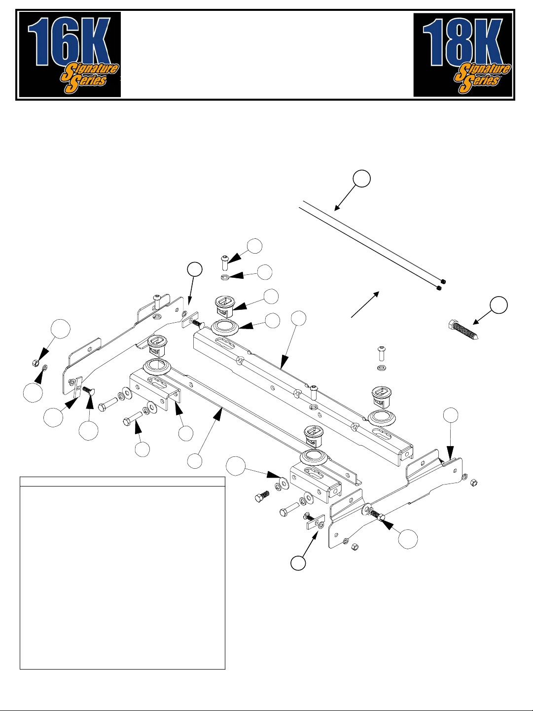
5
17
14
13
12
11
2
9
3
PART QTY.
1. FRONT BASE RAIL (CHANNEL) (1)
2. REAR RAIL BRACKETS (2)
3. REAR BASE RAIL (ANGLE) (1)
4. FRAME BRACKET (2)
5. 5/8-11 BUTTON HEAD SCREW (4)
6. 5/8 LOCK WASHER (12)
7. PUCK (4)
8. TRIM RING (4)
9. 5/8-11 GR 8 BOLT 4" LONG (3)
10. 5/8-11 GR 8 BOLT 1 1/2" LONG (5)
11. 1/2-13 GR 8 CARRIAGE BOLT 1 1/2" LONG (4)
12. BOLT PLATE (4)
13. 1/2 LOCK WASHER (4)
14. 1/2-13 GR 8 NUT (4)
15. 5/8 FLAT WASHER (4)
16. PULL WIRE (2)
17. FRAME HOLE SPACER WASHER (SMALLER) (2)
18. FRAME HOLE SPACER WASHER (LARGER) (2)
19. 5/8-11 X 3 1/2" WITH POINT (1)
15
16
6
Front of
7
vehicle
19
1
8
4
10
18
Figure 1
For Installation Assistance or Technical Help, Call 1-888-521-0510
30064IN – 8-21-08, rev E PCN11321 ©2005, 2008 CEQUENT TOWING PRODUCTS, INC. Litho in USA
Page 2
WARNING:
Failure to follow all of these instructions may result in death or serious injury!
INDEX
1. GUIDELINES FOR MATCHING TOW VEHICLE AND TRAILER P. 2-4
2. ASSEMBLY INSTRUCTIONS P. 5-9
3. CEQUENT TOWING PRODUCTS SEVEN YEAR LIMITED WARRANTY P. 10
GUIDELINES FOR MATCHING HITCH TRUCK AND TRAILER
WARNING:
Failure to check and follow tow ratings could result in tow vehicle
damage or truck and trailer separation while towing.
•Trailer and its contents together must not exceed truck, hitch and/or trailer tow
ratings.
•Towing vehicle must have a manufacturer’s rated towing capacity equal to or
greater than the gross trailer weight (dry weight of the trailer plus payload of the
trailer). (Figure 2)
•Gross weight of trailer must not exceed fifth wheel hitch rating.
•King pin weight must not exceed fifth wheel rating (Figure 3). If in doubt have king
pin weight measured by qualified facility.
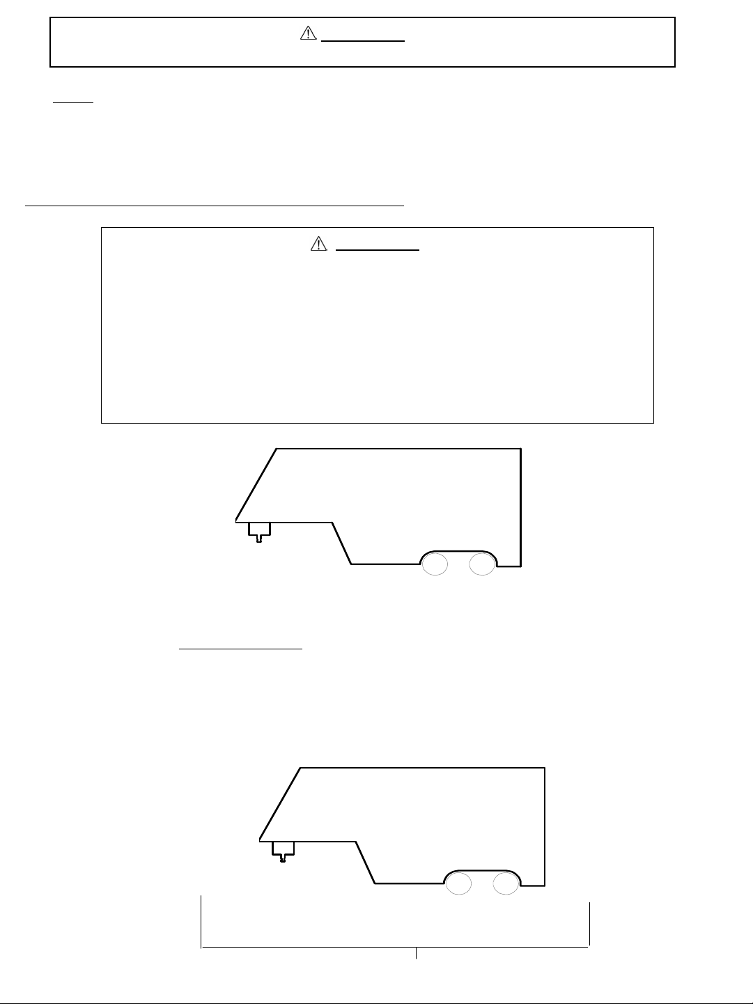
FACTORY TRAILER + FULL WATER
TANKS + CARGO, ETC.
= GROSS TRAILER WEIGHT
Figure 2
1. Check Tow Ratings:
Vehicle Tow Rating:_______________________.
Signature Series Hitch Rating:__________________
Gross Tra iler Weight (Figure 2):______________.
*Trailer weight should be the lowest of these recorded ratings for safe towing conditions.
2. Cequent Towing Products hitches are designed for use with recreational fifth wheel trailers only. Hitch applications other than
recreational fifth wheel trailers must be approved in writing by Cequent Towing Products’ Engineering Department.
3. Use only a SAE 2-inch kingpin with your Signature Series Fifth Wheel Hitch.
4. Approximately 15%-25% of trailer weight should be on hitch (Pin Weight)(Figure 3).
Figure 3
.
15-25%
GROSS TRAILER
WEIGHT
(PIN WEIGHT)
30064IN – 8-21-08, rev E PCN11321 ©2005, 2008 CEQUENT TOWING PRODUCTS, INC. Litho in USA
75-85%
GROSS TRAILER
WEIGHT
2
Page 3
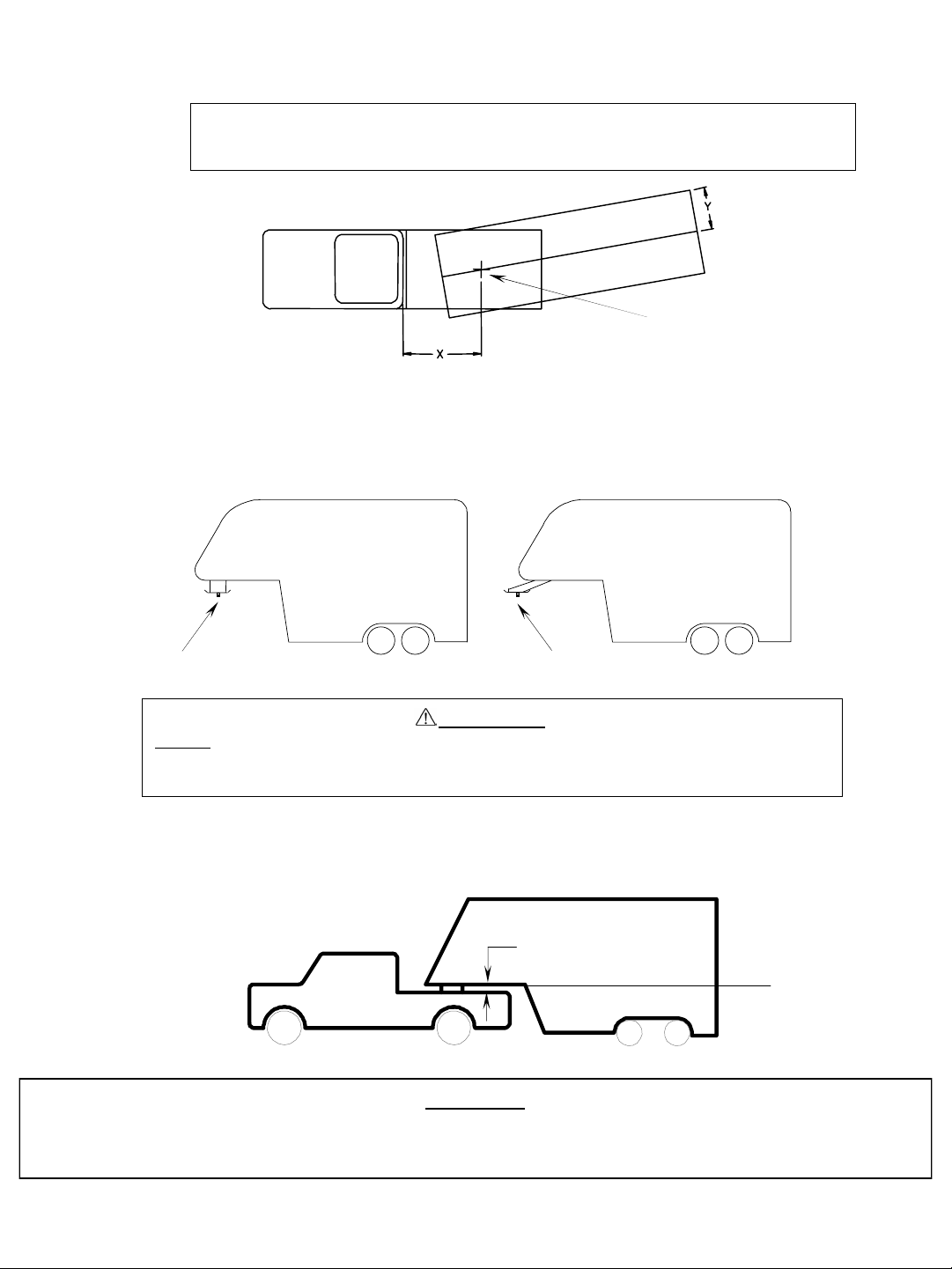
5. Trucks come in many different configurat ions. Cequent Towing Products’ hitches are designed for use in light trucks such as the
Ford F-Series, the Chevy Silverado and the Dodge Ram. Cequent Towing Products recommends the use of long bed (8ft) light
trucks for the best combination in truck - trailer turning clearance.
Rule of thumb: The distance from the back of the truck cab to the center of the rear truck
axle (“X” in Figure 4), should be approximately 4 inches greater than one-
half the trailer width (“ Y” in Figure 4).
RV TRAILER
Figure 4
TRUCK
6. If a short bed pickup (less than 8 ft. but longer than 6 ft.) is to be used for towing, Cequent Towing Products recommends the
trailer be equipped with an extended pin box or a SIDEWINDER Pinbox Coupler to help gain additional truck - trailer turning
clearance (See trailer manufacturer for extended pinbox options or your hitch installer for a SIDEWINDER Pinbox Co upler)
(Figure 5). It also may be helpful to add a
maneuvering. If the pickup bed is less than 6 ft., a SIDEWINDER Pinbox Coupler MUST BE INSTALLED ON THE TRAILER.
Figure 5
Conventional Pin Box
Signature Series Slider for increased turning clearance for low speed, non-highway
Extended Pin Box
or SIDEWINDER
KING PIN
WARNING:
Do Not install this fifth wheel hitch on or attempt to tow with a short bed pickup
truck that has a bed shorter than 6 ft. unless the trailer is equiped with a
SIDEWINDER Pinbox Coupler!
7. The height of the hitch and the pin box should be adjusted so the trailer is approximately level as it is towed. Allow
approximately 6 inches clearance between the top of the pickup walls and the underside of the front of the trailer for pitch and
roll of the trailer. (Figure 6). Allow more clearance between pickup walls and trailer for off road use.
Figure 6
Approximately 6 Inches
Level Trailer
CAUTION:
The measurements above are guidelines. If your measurements are close to these numbers re-check clearances. If
vehicle and/or trailer has any added bed vicinity accessories (i.e. fairings, air dams, ground effects, bed rails, etc.).
Additional dimensioning and clearance checks have to be made.
30064IN – 8-21-08, rev E PCN11321 ©2005, 2008 CEQUENT TOWING PRODUCTS, INC. Litho in USA
3
Page 4
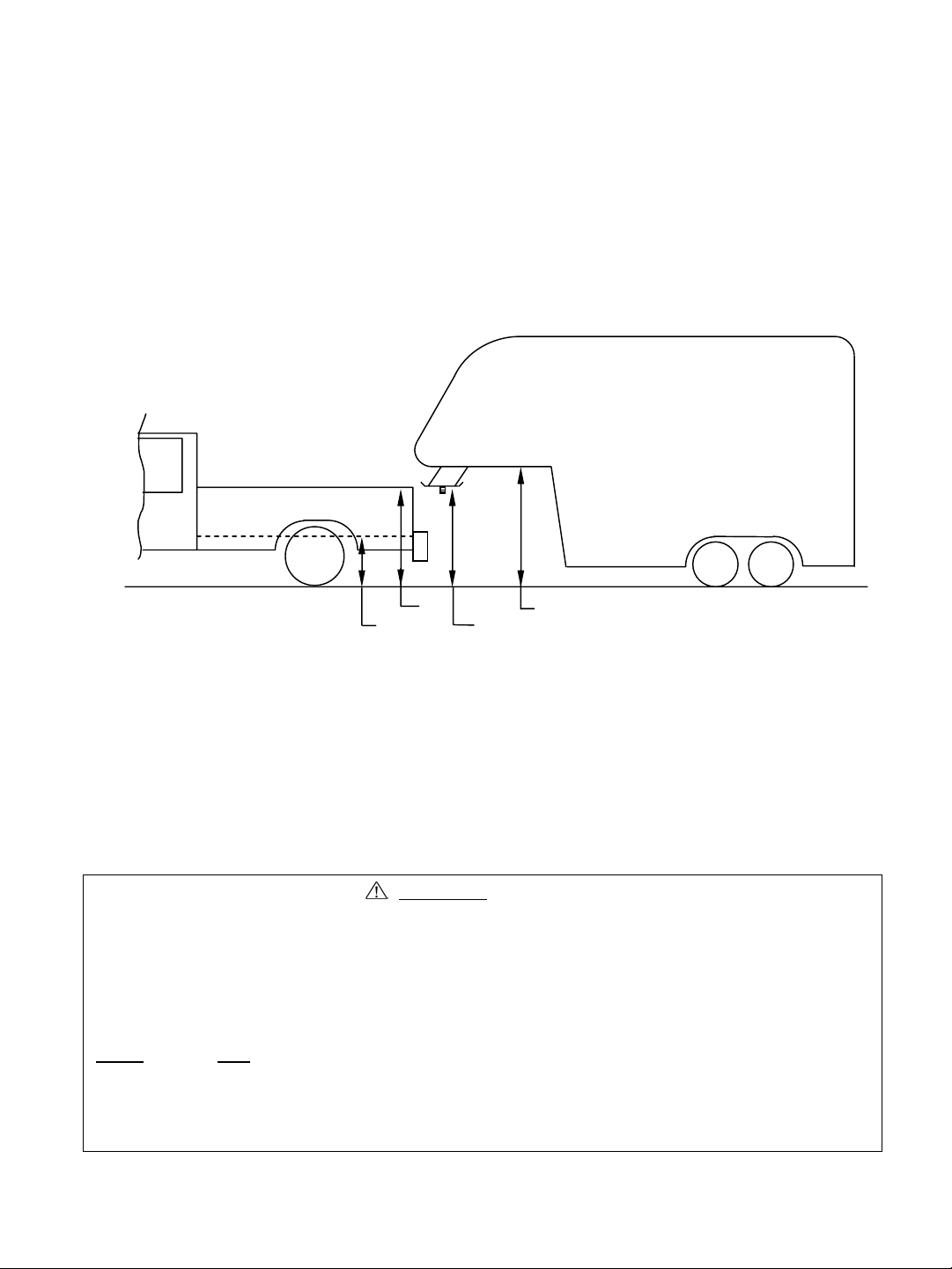
8. Hitch height determination:
With trailer leveled and on level ground measure from the ground to the king pin box (“A” in Figure 7). Secondly measure from
the height of the inside of the truck bed (“B” in Figure 7). Determine the amount of clearance over the side rails ( “C” and “D” in
Figure 7), as mentioned in Note 7.
Hitch Height = A – B + 2”
The 2” value is an estimate of suspension compression due to king pin weight of the trailer. This compression could range
between 1”-5” depending on the truck being used and the trailer being towed.
D – C + 2” > 6” as in Note 7.
C
B
9. If a lube plate is to be used with a Signature Series 5thWheel it must be at least 12” in diameter. Cequent Towing Products offers
this optional lube plate as part # 83001 / 40001.
A
Figure 7
D
*MEASURED WITH TRAILER LEVEL,
ON LEVEL GROUND
WARNING:
•Connection for trailer wiring must be located at the side of the truck bed between the driver’s
seat and the rear wheel to prevent operators from working between the truck and trailer.
•Avoid putting any part of your body under the trailer or between the truck and trailer.
Unexpected or accidental movement of the truck or the trailer can cause serious injury or death
•If you must place any part of your body under the trailer or between the truck and trailer you
MUST
perform ALL of the following steps:
•Check that the truck transmission is in park
•Check that the emergency brake is on
•Block in front of and behind all trailer tires
•Check that the trailer landing gear are resting on firm ground
30064IN – 8-21-08, rev E PCN11321 ©2005, 2008 CEQUENT TOWING PRODUCTS, INC. Litho in USA
4
Page 5

GENERAL INSTRUCTIONS FOR FIFTH WHEEL INSTALLATION
TOOLS
3/16" Drill 15/16" Socket & Open End Wrench
21/32" Drill 200 lb-ft Torque Wrench
3/8”, 1/2”, 5/8”, 3/4” Hex sockets 2-1/2” Hole Saw OR 2 1/2” Greenlee Knockout Punch
10 mm Hex socket Socket wrench extension (6 inch)
5/8-11 x 3 1/2” w/point
1. The following instructions should be used to mount the 5th wheel. Care and attention to detail will ensure a quick
quality installation. Check parts against parts list to become familiar with parts in kit. (Figure 1)
2. Raise rear of truck high enough to allow jack stands to be placed under rear spring hanger bracket of truck. This
will provide maximum room to install the 5th wheel brackets.
WARNING:
If the truck is raised, be sure that the truck is properly blocked and restrained to prevent the truck from falling.
Failure to do so may result in the truck suddenly falling, causing death or serious injury.
3. Plastic drop-in bed liners must be cut out of the way. Remove plastic bed liner if applicable. Spray-in bed liners
and bed mats less than 1/4” thick will work with normal installation instructions. Note: Consult installer for
recommended curing time on spray-in liner before cutting holes through bed.
CAUTION:
Check for obstructions before drilling. Failure to do so could result in damaged fuel or brake lines, structural
members, etc. CEQUENT TOWING PRODUCTS does its best to communicate tow vehicle manufacturer
changes; however, it is ultimately the responsibility of the installer to prevent damage due to installation.
4. Use only CEQUENT TOWING PRODUCTS supplied bolts, nuts, and washers to install this kit. All bolts and nuts
are grade 8 unless specified otherwise.
5. These instructions are intended for a specific group of trucks. If these instructions do not apply to your vehicle,
contact Technical Service to get proper instructions. Each frame bracket must be bolted to the vehicle frame with
two bolts.
CAUTION:
These instructions are guidelines only. Actual installation is the responsibility of the installer and the owner.
Always measure truck and trailer before installing hitch to be sure that there is clearance at the cab and at the
bumper to allow for turns.
6. Detach chassis exhaust hanger bracket hardware from chassis bed channels at two locations using a 10mm socket
wrench (Figure 8). Rotate wire harness 90° clockwise (Figures 8 and 9). Remove spare tire according to vehicle
owners manual.
Wire harness
Front of
Bed Channel
F
r
a
m
e
Bed Channel
E
x
h
a
u
s
t
F
r
a
m
e
Exhaust ha nger
bracket
2 places
vehicle
Wire harness
View from rear
of vehicle
Bed Channel
Figure 8
30064IN – 8-21-08, rev E PCN11321 ©2005, 2008 CEQUENT TOWING PRODUCTS, INC. Litho in USA
Figure 9
5
Page 6

6. Insert rails as shown in the following steps (FIGURES 10 through 12). Front (channel) rail should be inserted first
flat side up followed by rear (angle) rail flat side down with holes toward rear of vehicle.
Bed Channel
F
r
a
m
e
E
x
h
a
u
s
t
a
m
e
Bed Channel
Bed Channel
Step 2: Rest both ends of the front rail
on the chassis rails and slide the rail
forward.
F
r
up from the rear passenger side and
while flexing down the brake line
bracket for clearance place the end of
the rail on the driver side of the
chassis frame and rotate the
passenger side over the exhaust.
Step 1: Slide the front (channel) rail
Figure 10
F
r
a
m
e
Front of
vehicle
Bed Channel
Bed Channel
E
x
h
a
u
s
t
F
r
a
m
e
Step 3: Slide rear rail between
chassis frame and truck bed
from driver side wheel well until
resting evenly on both sides of
chassis frame rails.
Figure 11
Bed Channel
Bed Channel
F
r
a
m
e
E
x
h
a
u
s
t
F
r
a
m
e
Bed Channel
Figure 12
Bed Channel
30064IN – 8-21-08, rev E PCN11321 ©2005, 2008 CEQUENT TOWING PRODUCTS, INC. Litho in USA
6
Page 7

7. Attach rear rail brackets to rear rail angle using 5/8” X 4” (three) bolts, 5/8” X 1 1/2” bolt, lock washers, flat washers,
and welded nuts on rear rail angle (Figure 13). Use the 1 1/2” bolt for attaching the passenger side bracket inside
location. Tighten bolts to hand tight. First torque driver side bolts to 180 ft.lbs. then torque passenger side to 180
ft. lbs.
5/8” X 4” hex head bolts
3 places
5/8” X 1 1/2” hex head bolt
5/8” washers
5/8” lock washers
4 places
Front of
vehicle
Figure 13
Rear rail bracket
2 places
8. Loosely attach frame brackets to rails using 5/8” X 1 1/2" long bolts, flat washer & lock washers, (Figure 14).
5/8” lock washer
4 places
5/8” X 1 ½” bolts
4 places
5/8” flat washer
4 places
Front of
vehicle
Figure 14
9. Align holes in frame bracket with mounting holes in chassis rails (Figure 15). Remove jounce block from chassis
frame rails above axle.
Mounting holes
Front of
vehicle
Figure 15
Jounce Block
30064IN – 8-21-08, rev E PCN11321 ©2005, 2008 CEQUENT TOWING PRODUCTS, INC. Litho in USA
7
Page 8

10. Slide 17/32” washers and bolt plates over pull wire then thread pull wire onto 1/2” X 1 1/2” carriage bolts
(Figure 16). Insert free end of wire through hole vacated by the jounce block and guide wire to mounting holes
aligned with chassis frame and bracket (Figure 15). Pull wire until carriage bolt is mated with square hole in the
bolt plate and washer is filling mounting hole in chassis frame and threaded portion of bolt is protruding from
chassis rails (Figure 17). Unthread pull wire and repeat step for all four mounting hole locations.
Pull wire
17/32” washer
Note: Smaller outside diameter on
forward mounting holes.
Larger outside diameter on rearward
mounting holes
Bracket
Bolt plate
1/2” X 1 1/2” carriage bolt
Figure 16
Washer, filling larger
hole in frame
Bolt plate
1/2” X 1 1/2” carriage bolt
Frame rails
Figure 17
11. Loosely attach frame bracket to frame rails using 5/8” nuts and lock washers, tighten until hand tight (Figure 18).
Re-attach jounce block to the chassis frame rail.
Nut
4 places
Screw pointed bolt
in welded nut
4 places
Lock washer
4 places
Jounce block
2 places
Front of
vehicle
Figure 18
30064IN – 8-21-08, rev E PCN11321 ©2005, 2008 CEQUENT TOWING PRODUCTS, INC. Litho in USA
8
Page 9

12. Using pointed bolt (Figure 19), screw pointed bolt in to the nut that is welded to the rail assembly until a prick mark
is clearly visible on the truck bed (Figure 18). If access to the fourth welded nut is not possible due to vehicle
obstructions, the fourth prick mark should be marked on the bed based upon measuring from the other prick marks
(Figure 20). If you have a plastic bed liner cut 19” X 4” slots in plastic drop-in bed liner measured from prick marks
in truck bed. If the Signature Series slider fifth wheel assembly is used, then see fifth wheel assembly instructions for
slot cut dimensions.
Figure 19
Prick mark
Cut bed liner
19"
4"
Figure 20
Truck Bed
Cut bed liner
30"
13"
**Measure distance for
cutting plastic bed liner.
3"
2"
Prick mark
Tailgate
13. Move rails rearward or forward to prevent interference with hole drilling or punching of truck bed.
CAUTION:
Check for obstructions before drilling. Failure to do so could result in damaged fuel or brake lines, structural
members, etc. CEQUENT TOWING PRODUCTS does its best to communicate tow vehicle manufacturer
changes; however, it is ultimately the responsibility of the installer to prevent damage due to installation.
14. Drill pilot holes in truck bed at prick mark locations. With hole saw or knockout punch create 2 1/2” hole
centered at pilot holes. Note: Consult installer for recommended curing time on spray-in liner before cutting
holes through bed. Optional: Spray under coating around 2 1/2” holes to prevent rusting.
15. Loosely reattach rails to frame bracket.
30064IN – 8-21-08, rev E PCN11321 ©2005, 2008 CEQUENT TOWING PRODUCTS, INC. Litho in USA
9
Page 10

16. From truck bed attach pucks and trim rings to rails using 5/8” button head screw and lock washer (Figure 21).
Tighten to 100ft.lbs. torque.
5/8” BUTTON HEAD
4 PLACES
Figure 21
5/8” LOCK W ASHER
4 PLACES
PUCK
4 PLACES
TRIM RING
4 PLACES
Truck Bed
Puck Plug
Puck Assembly
Figure 22
17. Insert puck plugs in plugs whenever pucks are not in use. (Figure 22)
18. Install Signature Series 5th wheel per hitch assembly instructions.
19. Torque hitch assembly bolts per hitch instructions.
20. Torque all 5/8”and 1/2” rail kit hex bolts to 170ft.lbs
21. Replace any brake lines and spare tire that may have been removed/relocated.
30064IN – 8-21-08, rev E PCN11321 ©2005, 2008 CEQUENT TOWING PRODUCTS, INC. Litho in USA
10
Page 11

NOTES
SEVEN YEAR LIMITED WARRANTY
Hitches - Custom Receivers
Cequent Towing Products warrants the Signature Series 5th Wheel Hitch Mounting Kits from date of purchase
against defects in material and workmanship under normal use and service, ordinary wear and tear
excepted, for 7 years of ownership to the original consumer purchaser when a Cequent Towing Products
Signature Series 5th Wheel Hitch is used.
Cequent Towing Products will replace FREE OF CHARGE any part which proves defective in material or
workmanship when presented to any Cequent Towing Products dealer, Cequent Towing Products
Warehouse or returned to factory. TRANSPORTATION CHARGES PREPAID, at the address below.
THIS WARRANTY IS LIMITED TO DEFECTIVE PARTS REPLACEMENT ONLY. LABOR CHARGES
AND/OR DAMAGE INCURRED IN INSTALLATION OR REPLACEMENT AS WELL AS INCIDENTAL
AND CONSEQUENTIAL DAMAGES CONNECTED THEREWITH ARE EXCLUDED.
Some states do not allow the exclusion or limitation of incidental or consequential damages, so the above
limitation or exclusion may not apply to you.
Any damage to the Signature Series 5th Wheel Hitch as a result of misuse, abuse, neglect, accident, improper
installation, or any use violative of instructions furnished by us, WILL VOID THE WARRANTY.
This warranty gives you specific legal rights, and you may also have other rights which vary from state to
state. In the event of a problem with warranty service or performance, you may be able to go to a small
claims court, or a federal district court.
Cequent Towing Products, Inc.
47774 Anchor Court W.
Plymouth MI 48170
30064IN – 8-21-08, rev E PCN11321 ©2005, 2008 CEQUENT TOWING PRODUCTS, INC. Litho in USA
11
 Loading...