

Page 1

Operating instructions
Remote Control "HT-5", 2.4 GHz
Item No. 1414497
Version 04/16
Page 2

2
Table of Contents
Page
1. Introduction .......................................................................................................................................................... 3
2. Explanation of Symbols ....................................................................................................................................... 3
3. Intended Use .......................................................................................................................................................4
4. Product Description .............................................................................................................................................4
5. Scope of Delivery .................................................................................................................................................5
6. Safety Notes ........................................................................................................................................................ 5
a) General Information ....................................................................................................................................... 5
b) Operation ....................................................................................................................................................... 6
7. Battery and Rechargeable Battery Notes ............................................................................................................7
8. Charging the Rechargeable Batteries ..................................................................................................................7
9. Operating Elements of the Transmitter ................................................................................................................8
10. Setting up the Transmitter ....................................................................................................................................9
a) Inserting the Batteries ....................................................................................................................................9
b) Switching on the Transmitter .........................................................................................................................9
c) Setting the Control Lever Length ................................................................................................................. 10
11. Setting up the Receiver .....................................................................................................................................11
a) Receiver Connection ................................................................................................................................... 11
b) Installing the Receiver ................................................................................................................................. 12
12. Installing the Servos ..........................................................................................................................................13
13. Setting the Trim ..................................................................................................................................................14
14. Checking the Servo Directions of Travel ............................................................................................................15
a) Checking the Control Lever Functions ........................................................................................................15
b) Checking the Switching Channel Function .................................................................................................. 17
15. Switching the Servo Directions of Travel ...........................................................................................................18
16. Changing the Control Lever Allocation ..............................................................................................................19
17. Delta Mixer .........................................................................................................................................................20
18. Servo Path Limitation .........................................................................................................................................22
19. Switching the Digital Code .................................................................................................................................23
20. Binding Function ................................................................................................................................................24
21. Simulator Function, Student Transmitter Function .............................................................................................25
22. Maintenance and Care ......................................................................................................................................25
23. Declaration of Conformity (DOC) .......................................................................................................................25
24. Disposal ............................................................................................................................................................. 26
a) General Information ..................................................................................................................................... 26
b) Batteries and Rechargeable Batteries ......................................................................................................... 26
25. Troubleshooting .................................................................................................................................................27
26. Technical Data ................................................................................................................................................... 28
a) Transmitter...................................................................................................................................................28
b) Receiver ......................................................................................................................................................28
Page 3

3
1. Introduction
Dear Customer,
Thank you for purchasing this product.
This product complies with the statutory national and European requirements.
To maintain this status and to ensure safe operation, you as the user must observe these operating instructions!
These operating instructions are part of this product. They contain important notes on commissioning and
handling. Also consider this if you pass on the product to any third party.
Therefore, retain these operating instructions for reference!
All company names and product names are trademarks of their respective owners. All rights reserved.
If there are any technical questions, please contact:
International: www.conrad.com/contact
United Kingdom: www.conrad-electronic.co.uk/contact
2. Explanation of Symbols
The symbol with the exclamation mark points out particular dangers associated with handling, function or
operation.
The arrow symbol indicates special advice and operating information.
Page 4

4
3. Intended Use
The 5-channel remote control "HT-5" is solely designed for private use in the eld of model construction and the operating times associated with it. This system is not suitable for industrial use, such as controlling machines or equipment.
Any use other than that described above can damage the product and involves additional risks such as short circuit,
re, electric shock, etc. The product must not be technically modied or rebuilt! The safety information must be observed at all times!
Observe all safety information in these operating instructions. They contain important information on han-
dling of the product.
You are solely responsible for the safe operation of your remote control and your model!
4. Product Description
The 5-channel remote control system "HT-5" is a radio control system that is mainly ideal for controlling model planes.
If necessary, the remote control can also be used to control model vehicles, model ships or simple 4-channel model
helicopters (speed-controlled).
The ve proportional control channels can be used to remote-control the different control functions independently of
each other. The ergonomic casing ts comfortably into your hand and allows for easy and safe operation of the model
and the transmitter.
For operation, 4 AA/mignon batteries (e.g. Conrad item no.: 652507, pack of 4, order 1x) are required for the transmitter.
Where no ight controller or speed controller with BEC switch is used, you also need 4 AA/mignon batteries for the
receiver (e.g. item no. 652507, order 1x) or 4 AA/mignon rechargeable batteries with the corresponding battery holder.
Alternatively, 4- or 5-cell NiMH receiver batteries (rated voltage 4.8 - 6.0 V) can also be used with the switch cable. The
receiver may also be operated with a 2-cell LiPo battery (rated voltage 7.4 V), but in this case the connected servos
also must be high-voltage-capable.
Page 5

5
5. Scope of Delivery
• Remote control transmitter
• Remote control receiver
• Binding plug
• Operating instructions on CD
Current operating instructions:
1. Open www.conrad.com/downloads in a browser or scan the QR-code shown on
the right.
2. Select the document type and language, and then enter the corresponding order
number in the search eld. After searching starts, you can download the documents found.
6. Safety Notes
In case of damage caused by non-compliance with these operating instructions, the warranty/guar-
antee will expire. We do not assume any liability for consequential damage!
We do not assume any liability for property damage or personal injury caused by improper use or
non-compliance with the safety instructions! In such cases the warranty/guarantee is voided.
Normal wear and tear in operation and damage due to accidents (like the receiver aerial being torn off, the
receiver casing broken etc.) are excluded from the warranty.
Dear customer, these safety instructions are not only for the protection of the product but also for your own
safety and that of other people. Therefore, read this chapter very carefully before taking the product into
operation!
a) General Information
• The unauthorized conversion and/or modication of the product is inadmissible for safety and approval reasons
(CE).
• This product is not a toy and not suitable for children under 14 years of age.
• The product must not become damp or wet.
• Taking out private liability insurance is recommended. If you already have one, get some information on whether or
not the operation of a radio-operated model is covered by your insurance.
• Do not connect the drive motor to electric models before the receiver system has been installed completely. This
ensures that the drive motor does not start unintentionally.
• Do not leave the packaging material lying around carelessly as it can become a dangerous toy for children.
Page 6

6
• Please check the functional safety of your model and of the remote control system each time before you use the
model. Watch out for any visible damage such as defective plug connections or damaged cables. All movable parts
on the model have to be running smoothly. However, there must be no tolerance or 'play' in the bearing.
• The operation and handling of remote controlled models must be learned! If you have never controlled such a
model, start especially carefully to get used to how it responds to the remote commands. Do be patient!
• Should any questions arise that are not answered with the help of this operating manual, please contact our "Technical Advisory Service" (contact information see chapter 1) or another expert.
b) Operation
• If you do not yet have sufcient knowledge on how to deal with remote-controlled models, please contact an experienced model sportsman or a model construction club.
• When putting the device into operation, always turn on the transmitter rst. Then switch on the receiver in the model.
Otherwise, the model might show unpredictable responses! Avoid directing the tip of the aerial directly towards your
eyes.
• Before operating the model, check whether the stationary model reacts as expected to the commands of the remote
control.
• When you operate the model, always make sure that no parts of your body, other people or objects come within the
dangerous range of the motors or any other rotating drive parts.
• Improper operation may cause serious injury and property damage! Always make sure that the model is in your line
of sight and do not operate it at night.
• Only operate your model if your ability to respond is unrestricted. Fatigue or the inuence of alcohol or medication
can lead to wrong responses.
• Operate your model in an area where you do nor endanger any persons, animals or objects. Only operate it on
private sites or in places which are specically designated for this purpose.
• In case of a fault stop operating your model straight away and remove the cause of malfunction before you continue
to use the model.
• Do not operate your RC system during thunderstorms, beneath high-voltage power lines or in the proximity of radio
masts.
• Never switch off the remote control (transmitter) while the model is in use. To switch off the model, always switch off
the motor rst, then switch off the receiver. Only then may the remote control be switched off.
• Protect the remote control from dampness and heavy dirt.
• Do not expose the remote control to direct sunlight or excessive heat for a long period of time.
• If the batteries in the remote control are low, the range decreases. If the receiver batteries or rechargeable battery
in the receiver are low, the model will not respond correctly to the remote control.
If this is the case, stop driving immediately. Replace the batteries with new ones or recharge the receiver's recharge-
able battery.
• Do not take any risks when operating the product! Your own safety and that of your environment depends completely
on your responsible use of the model.
Page 7

7
7. Battery and Rechargeable Battery Notes
• Keep batteries/rechargeable batteries out of the reach of children.
• Do not leave any batteries/rechargeable batteries lying around openly. There is a risk of batteries being swallowed
by children or pets. If swallowed, consult a doctor immediately!
• Batteries/rechargeable batteries must never be short-circuited, disassembled or thrown into re. There is a danger
of explosion!
• Leaking or damaged batteries/rechargeable batteries can cause chemical burns to skin. Wear suitable protective
gloves when handling them.
• Do not recharge normal batteries. There is a risk of re and explosion! Charge only rechargeable batteries intended
for this; use suitable chargers.
• Always observe correct polarity (positive/+ and negative/-) when inserting the batteries/rechargeable batteries.
• If the device is not used for an extended period of time (e.g. storage), remove the inserted batteries/rechargeable
batteries from the remote control and the car to avoid damage from leaking batteries/rechargeable batteries.
• Recharge the rechargeable batteries about every 3 months. Otherwise, so-called deep discharge may result, rendering the rechargeable batteries useless.
• Always replace the entire set of batteries or rechargeable batteries. Never mix fully charged batteries/rechargeable
batteries with partially discharged ones. Always use batteries or rechargeable batteries of the same type and manufacturer.
• Never mix batteries and rechargeable batteries!
• For reasons of operational safety, only use batteries and rechargeable batteries for the remote control transmitter.
8. Charging Rechargeable Batteries
If you use NiMH rechargeable batteries for power supply of the receiver, they are usually at at delivery and must be
charged.
Please note:
Before a NiMH rechargeable battery reaches maximum capacity, several complete discharge and charge
cycles are necessary.
Always discharge the rechargeable battery at regular intervals, since charging a "half-full" rechargeable bat-
tery several times can cause a so-called lazy battery effect. This means that the rechargeable battery loses
capacity. It no longer provides all of its stored energy, and the operating time of the model is reduced.
If you use several rechargeable batteries, purchasing a high-quality charger may be worthwhile. Such a
charger usually has a quick-charging feature.
Page 8

8
9. Operating Elements of the Transmitter
Figure 1
1 Transmitter aerial
2 Carrying handle
3 Trim button for elevator function
4 Toggle switch for channel 5
5 Control lever for elevator and aileron function
6 Trim button for aileron function
7 LED display
8 On/off switch
9 Reverse switch
10 Delta mixer switch
11 Binding button
12 Trim button for rudder function
13 Control lever for rudder and motor function
14 Trim button for motor function
15 Toggle switch for servo path limitation
16 Carrying belt eyelet
Page 9
9
10. Setting up the Transmitter
In the further course of these instructions, gures in the text always refer to the adjacent gure or the gures
within the section. References to other gures are indicated with the corresponding gure number.
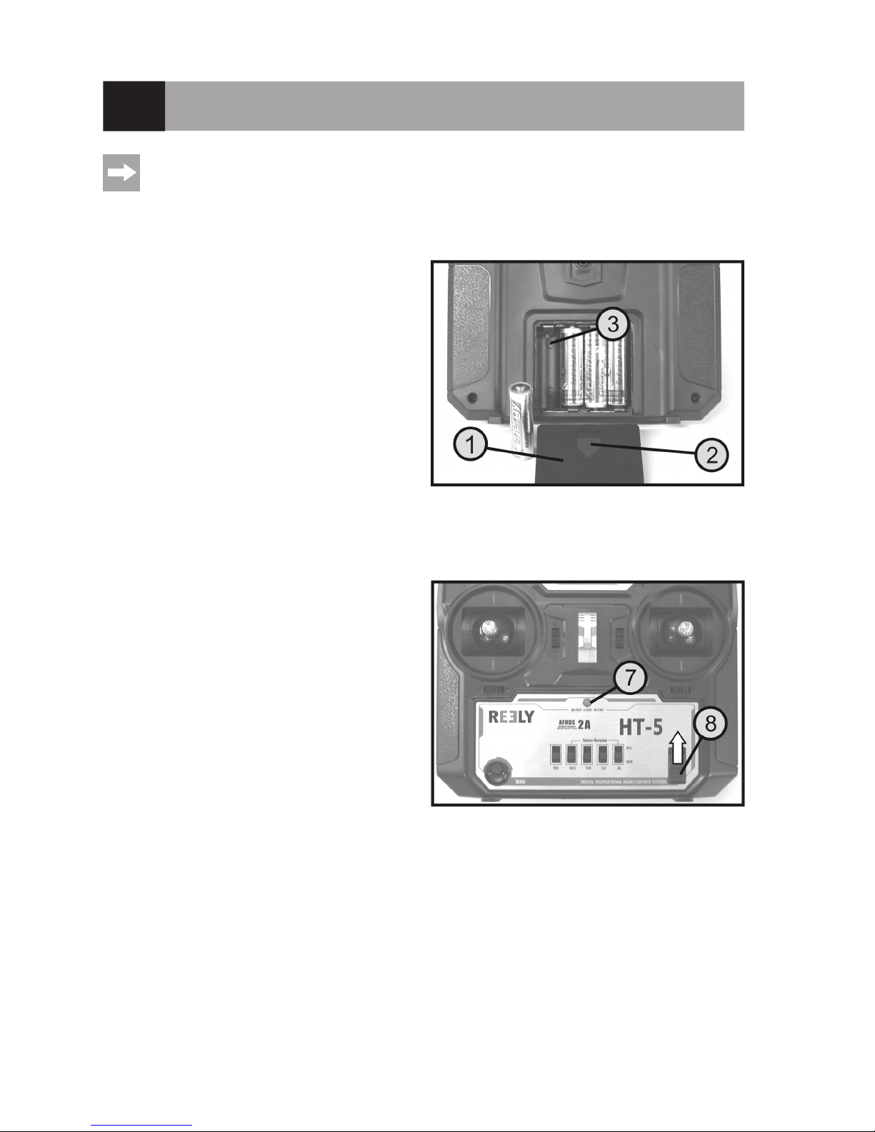
a) Inserting the Batteries
For the power supply of the transmitter you will need 4
alkaline batteries (e.g. item no. 652507, pack of 4, order 1)
of the size AA/mignon.
Proceed as follows to insert the batteries:
The battery compartment lid (1) is located on the back of
the transmitter. Press the corrugated area (2) and push off
the lid downwards.
Ensure that the polarity is correct when inserting the 4 batteries. A corresponding note (3) is located on the bottom
of the battery compartment.
Then slide the lid of the battery compartment back on from
the bottom until the locking mechanism engages.
b) Switching on the Transmitter
When new batteries are inserted, switch on the transmitter
with the function switch (see gure 1, item 8) for test purposes. For this, slide the operating switch from the bottom
(off) to the top (on).
The transmitter emits a short signal sound and the LED
display (also see gure 1, item 7) lights up green permanently.
If the voltage supply drops below 5.0 V, the LED display
switches from green to orange to red and thus indicates
threatening undersupply of the transmitter. The model
should then no longer be operated. When the voltage
drops below approx. 4.0 V, the LED display starts ashing
red and the transmitter emits acoustic warning sounds at
regular intervals. In this case, operation of the model must
be ceased as quickly as possible. Insert new batteries for
further operation of the transmitter.
After you have veried the correct function of your transmitter, switch it off again.
Figure 2
Figure 3
Page 10

10
c) Setting the Control Lever Length
You can adjust the length of the control levers, depending
on your steering habits.
To do so simply hold the bottom part of the grip (1) and
turn the upper part (2) up anti-clockwise.
You can now set the length of the control lever by turning
the bottom part of the grip.
Finally, tighten the upper part of the grip back up.
Figure 4
Page 11

11
11. Setting up the Receiver
a) Receiver Connection
The receiver offers the possibility of connecting 5 servos
(receiver output "CH1", "CH2", "CH3", "CH4" and "CH5")
that are later assigned the following control functions in
the model:
"CH1" = Aileron/roll servo
"CH2" = Elevator/nod servo
"CH3" = Throttle servo/ight controller/speed controller
"CH4" = Rudder/tail servo
"CH5" = Special function
The receiver output "CH5" can be used for special functions such as landing aps, spoiler aps, retractable landing gear or switching functions.
The receiver output "CH6" is not used, since the transmit-
ter only transmits the rst ve channels.
At the "BAT" connection, a battery box (1) or a receiver
battery with switch cable (2) is connected if no ight controller or speed controller with BEC switch is used.
When using servos with high power demand,
we recommend to always use a receiver battery
pack.
The connections are designed for JR plug connectors. If
required, Futaba plugs can be used as well, if a key le or
a sharp knife is used to remove the narrow guide bridge
at the plug.
When connecting servos and speed controllers, always make sure of correct polarity of the plug connectors. The plugin connection for the positive lead (yellow, white or orange, depending on the manufacturer) must be connected to the
inner (left) pin contact. The plug-in connection for the negative lead (black or brown, depending on the manufacturer)
must be connected to the outer (right) pin contact.
First, switch on the transmitter and then the receiver. If the binding function is working correctly, the red LED indicator
in the receiver (see gure 5, item 3) lights up and the ve servos react to the movements of the control levers. Verify
correct receiver function and then switch the receiver off again.
If the servos do not react and the LEDs in the receiver do ash, perform binding (see chapter 20).
Figure 5
Page 12

12
b) Installing the Receiver
Installation of the receiver depends on the model. For this reason, you should always follow the recommendations of
the model manufacturer regarding the installation.
Regardless of the model, you should always try to install the receiver so that it is protected from dust, dirt, moisture,
heat and vibration in the best possible way and is not located in the direct proximity of the rechargeable battery/motor
lines.
Keep enough distance from motors and electronic ight or speed controllers. Metal or carbon parts have a shielding
effect and thus may considerably impair reception. In this case, it is mandatory to relocate the aerial outwards through
a bore in the fuselage.
Two-sided adhesive foam (servo tape) or rubber rings that hold the foam-wrapped receiver securely in place are
suitable for fastening.
Attention!
The aerial wire (1) length is determined precise-
ly.
For this reason, you must not roll up the wire,
place it in a loop or cut it off. This would de-
crease the range signicantly and thus pose a
considerable safety risk.
Figure 6
Page 13

13
12. Installing the Servos
The installation of a servo (1) always depends on the
particular model used. Detailed information on this can be
found in the construction documents of the model.
Generally, however, try screwing in the servos in a vibration-dampened manner. This is why rubber bushings (2)
with metal sleeves (3) are usually included with the servos.
When linkages are stiff, the servos cannot assume the required positions. This causes higher power consumption
and the model cannot be controlled properly.
The linkages must work as smoothly as possible without
having any play in the bearings or deections.
Before installing the servo lever, take the transmitter and
then the receiver into operation and check the trim at the
remote control transmitter for correct middle position (see
following chapter).
Then always mount the servo stick at a 90° angle to the
linkage rods (see gure 8, sketch A).
The servo lever is at an angle to the linkage rod (see gure
8, sketch B), the control paths of the two control directions
will be unequal.
A slight mechanical inclination due to interlock of the servo
levers may be corrected with the trim later.
Figure 7
Figure 8
Page 14

14
13. Setting the Trim
The trim mostly serves to correct the slight inclination of the servo levers due to the interlock and the connected ir-
regular control movements. Additionally, there is the option to adjust the model in operation precisely, e.g. if it is not
ying straight although the control lever is in the middle position.
Then the linkage or rudder rods must be adjusted so that the trim has its original value (90°-range between servo lever
and rods) again and the model still runs straight.
The remote control "HT-5" has a nely tuned digital trimming with which the rst four control channels can be individually set with a trimming button (also see gure 1, items
3, 6, 12 and 14).
The trimming buttons are assigned the following control
functions:
Trimming button 3 = elevator servo "CH2"
Trimming button 6 = aileron/roll servo "CH1"
Trimming button 12 = rudder/tail servo "CH4"
Trimming button 14 = throttle servo "CH3"
To check the setting of the digital trimming, rst switch on
the transmitter and then the receiver. If a trimming button
is moved to the side or up or down and held, the transmitter will emit brief signal sounds in a quick sequence.
The servo of the respective control channel will change
the position of the servo lever in small steps.
When the end of the trimming range is reached, the signal sounds go out and the servo lever stops turning. If the
trimming button is then deected in the opposite direction and held, the signal sounds sound again and the servo lever
turns back to the middle position step by step.
When the middle position of the trimming range has been reached, the remote control issues a longer signal sound.
Now set the middle positioning of the trimming in all four channels and install the servo levers so that they are at a
90° angle to the rods. Since the servo levers and the servo axis are interlocked, very small inclinations of the servo
lever cannot always be avoided. In this case, the trimming of the respective channel must be adjusted slightly from the
middle to return to the 90° angle of the servo lever to the linkage rod (see gure 8).
The set trim value is automatically saved in the remote control and is retained even after switching it off and
on.
When using the electrical model with a ight controller, the trim for channel 3 also needs to be set to the middle value.
Figure 9
Page 15

15
14. Checking the Servo Directions of Travel
a) Checking the Control Lever Functions
For gure 10 for this section, see the next page.
Connect the servos inserted in the model to the receiver. Pay attention to the assignment of the receiver outputs as
described above.
If your model has two aileron servos, there is the possibility of operating both servos with a V-cable at the
receiver output "CH1".
Take the transmitter into operation, then the receiver. If attached correctly, the servos at outputs 1, 2, 3 and 4, or a
speed controller at output 3, should react in the right direction to the movements of the control levers according to the
illustrations in gure 10.
The linkage rods of the rudders must be adjusted so that the rudders are all aligned precisely centrally if the control
lever and the trimming are in the central position (also see top sketch in gure 10).
The left control lever for motor control can be pushed forward and back without being moved back to the
middle position by spring force. It always remains in the position into which it was last moved.
Using a throttle servo:
If the model is operated with a combustion engine, the throttle servo rods must be adjusted so that the motor runs idle
when the carburettor is nearly closed when the left control lever is in the bottom position. Only when the trim for the
motor function is also pushed all the way to the bottom, the carburettor must close completely so that the combustion
engine is switched off.
If the control lever is pushed to the top-most position, the throttle in the carburettor must be completely opened so that
the motor can run at full power.
Using an electrical motor with ight controller/speed controller:
An electronic ight controller/speed controller connected at the receiver output "CH3" must be set so that an electric
motor is off when the left control lever is in the bottom position. For electrical models, the ight controllers/speed
controllers often offer the option to teach in the respective control lever positions for "motor off" and "maximum perfor-
mance". Further information on this can be found in the operating instructions of the ight controller/speed controller.
Attention!
Only perform the motor test in an electric model when the model is reliably secured against rolling away.
Make sure that neither objects nor body parts are in the rotating and suction areas of the propeller during
the motor test.
If the servos or rudders react in precisely the opposite manner as shown in gure 10, the reverse switches (see following chapter) can swap the running direction of the respective servo.
Page 16

16
Figure 10
Page 17

17
b) Checking the Switching Channel Function
The additional switching channel "CH 5" is controlled with the toggle switch (also see gure 1, item 4). If, e.g., a servo
to control landing/spoiler aps, retractable landing gear or other special functions is connected at the receiver output
"CH 5", the servo lever is in the middle position when the toggle switch at the transmitter is in the middle position
( ) as well.
If the toggle switch is switched up ( ) or down ( ), the servo lever runs to the respective end position.
Figure 11
As an alternative to a servo, switching modules, e.g. for model lighting, can also be connected to the re-
ceiver output "CH 5".
Attention!
For channel 5, neither a trim function nor a path limitation are available. For this reason, the rods controlled
by the servo must be mechanically set up so that the full function is present but the servo is not limited
mechanically in its rotating movement.
Important!
Always switch on the transmitter rst, then the receiver. When you switch off the devices, always switch off
the receiver rst, then the transmitter.
Never switch off the remote control as long as the receiver is in operation. This can lead to unexpected
reactions by the model!
Page 18

18
15. Switching the Servo Directions of Travel
If the rudder movements are not according to gure 10,
you can switch the running direction of the servos at the
receiver outputs "CH1" to "CH 4" at the reverse switches
(also see gure 1, item 9). The switches at the transmitter
are assigned as follows:
"AIL" = Aileron/roll servo "CH 1"
"ELE" = Elevator servo "CH 2"
"THR" = Throttle servo/ight controller "CH 3"
"RUD" = Rudder/tail servo "CH 4"
If the switch is in the bottom position, the "regular" running
direction is set. If the switch is pushed to the top position,
"reversed" running direction is activated.
Please observe that the centre position of the servo/rudder may have to be adjusted after switching.
For the switching channel "CH 5", switching of the servo running direction at the transmitter is not possible.
Figure 12
Page 19
19
16. Changing the Control Lever Allocation
If you want to control your ight model according to the chart shown in gure 10 (mode II), you can skip this section.
If you prefer the throttle function on the right control lever and the elevator function on the left one (mode I), you may
convert the transmitter accordingly.
To make the necessary changes, some experience with remote control transmitters is required. Therefore you should
consult an experienced model maker or a model construction club if you do not feel capable of undertaking the procedures described in the following.
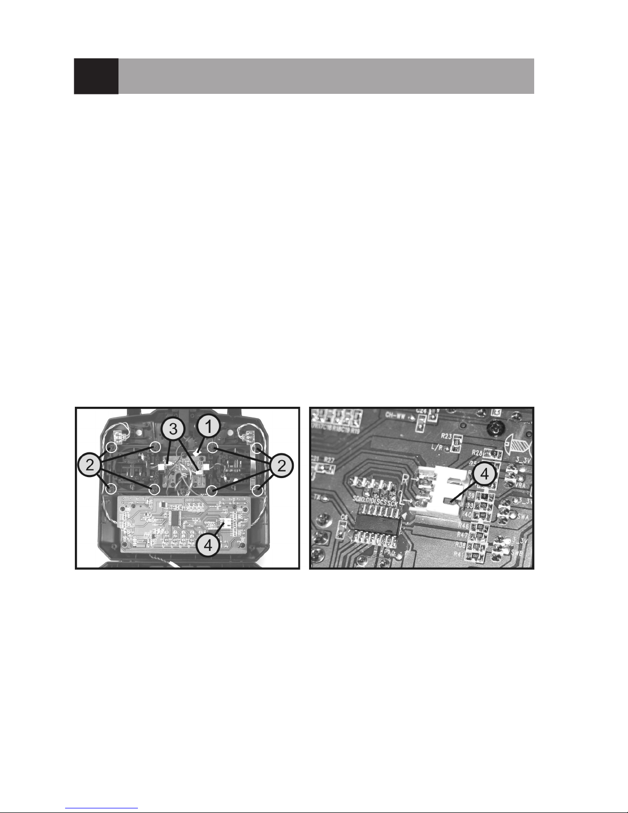
• Remove the transmitter batteries.
• Unscrew the four screws by means of a Phillips-tip screwdriver from the rear panel of the transmitter and lift the rear
panel carefully.
• After you have disconnected the plug connector of the student socket (1), you can fold the rear of the transmitter
down.
• For this, loosen the four screws at the control lever units (2) and swap the two units. You need to turn both control
lever units by 180° so that the connections of the control lever potentiometers (3) are aligned to the inside again.
• Then screw on the control lever units again.
• Use pointed pliers or pincers to pull the jumper (4) from the position "L" and reinsert it in position "R".
• Then close the connection plug of the student socket (1) again and place the rear panel on the transmitter housing.
Observe that no lines are caught between the housing halves.
• Tighten the four attachment screws of the rear wall again and check for correct function of the remote control.
Figure 13
Page 20

20
17. Delta Mixer
For gure 14 for this section, see the next page.
The remote control "HT-5" has a delta mixer that can be activated with the mixer switch (also see gure 1, item 10).
When the slider is in the bottom position, regular operation without mixer function is active. When the slider is put up,
the delta mixer is activated.
For a delta plane model with triangular wing, the ailerons also have to perform the elevator function. For this reason,
the channels "CH1" (aileron) and "CH2" (elevator) are mixed in the delta mixer. No matter whether the transmitter
controls the aileron or elevator function then, the two servos at the receiver outputs "CH1" and "CH2" will always react
at the same time then.
The servo of the right wing has to be connected to the receiver output "CH1" and the servo of the left wing to the
receiver output "CH2". The deections of the two rudder aps have to be according to the gures in gure 14.
If required, the servo directions can be corrected with the reverse switches.
Page 21

21
Figure 14
Page 22
22
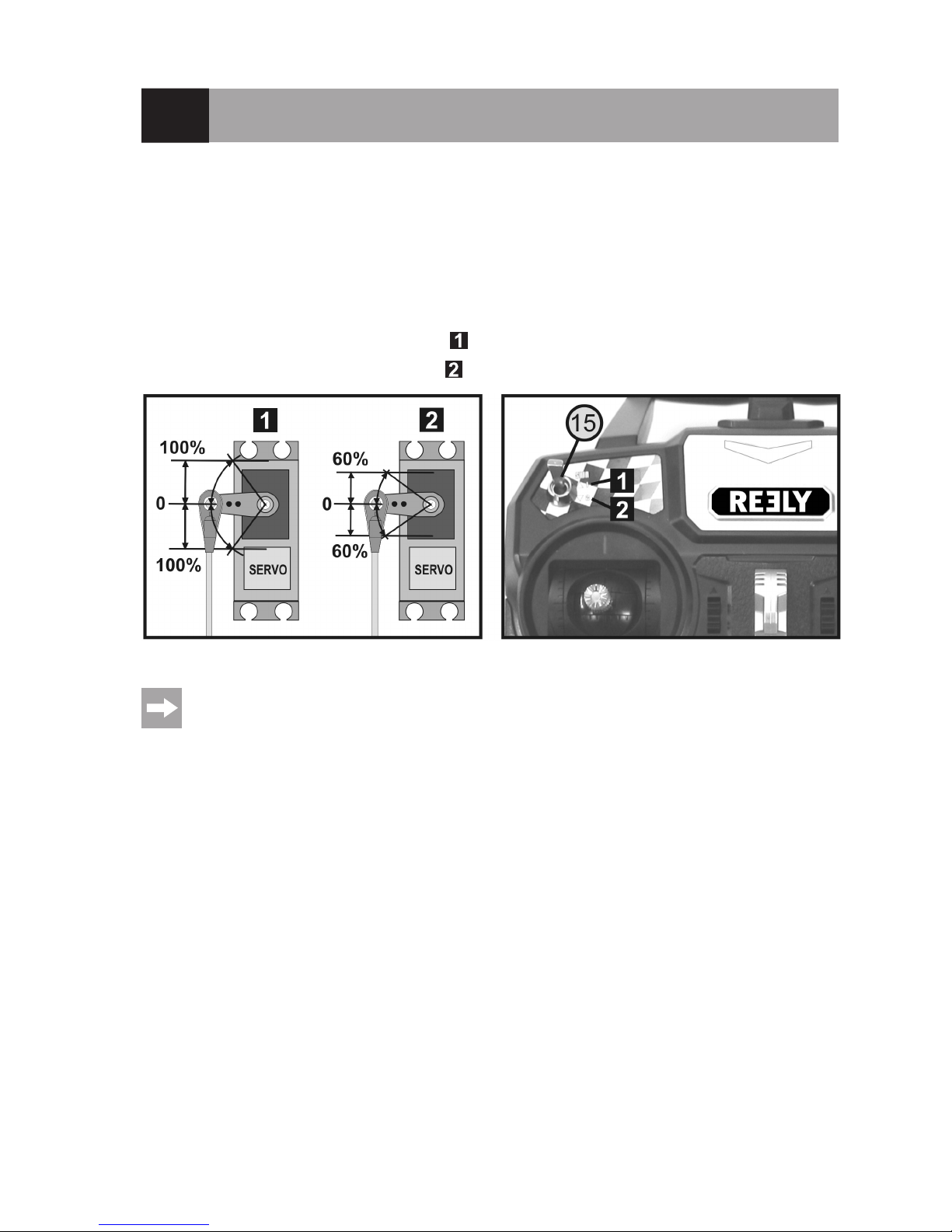
18. Servo Path Limitation
Use the servo path limitation or the dual rate function to reduce the servo deections of channels 1, 2 and 4 from
100% to 60%. You can use this function to simply and easily reduce the reaction sensitivity of a model which reacts
too aggressively at full extension.
Especially when a model is used for the rst time, it might not yet be clear how sensitively it responds to the control
commands. Therefore it is a proven method to reduce large rudder deections during ight.
The path limitation is switched with the switch at the upper left of the remote control transmitter (also see gure 1,
item 15).
If the switch is switched to the upper/front position ( ), 100% servo path are available.
If the switch is switched to the lower/rear position ( ), 60% servo path are available.
Figure 15
The rudder path reduction amount of 60% is xed ex works and cannot be changed by the user.
Page 23
23
19. Switching the Digital Code
The remote control transmitter enables you to control receivers with the digital code "AFHDS" and "AFHDS 2A". Ex
works, the transmitter is set to the enclosed "AFHDS 2A" encoded receiver.
If you want to operate a Reely-receiver with the digital code "AFHDS", the transmitter must be switched rst and then
the receiver must be newly bound to the transmitter (see following chapter).
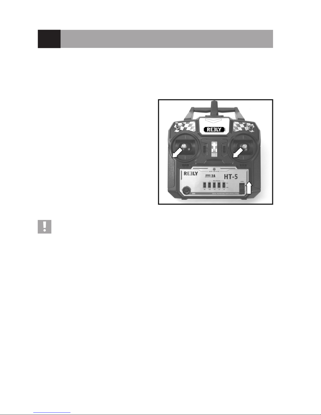
To switch the digital code at the transmitter, proceed as follows:
• Switch off the transmitter.
• Move the two control levers to the lower left corner and
keep it there.
• Switch on the transmitter with the on/off switch with the
control levers deected.
• Release the two control levers so that they move to the
centre position.
• If the LED display ashes, the transmitter has switched
to the digital code "AFHDS". If the LED display ashes
and the remote control also issues short signal sounds
in a cycle of one second, the transmitter has switched to
the digital code "AFHDS 2A".
• Switch off the transmitter so that the currently set digital
encoding is saved.
Important:
The receiver enclosed with the remote control system "HT-5" works with code "AFHDS 2A". Therefore,
always observe that the right code is programmed at the transmitter!
Figure 16
Page 24

24
20. Binding Function
To enable transmitter and receiver to work together, they must be bound by the same digital code. In the delivery state,
transmitter and receiver are aligned with each other and can be used at once. The binding settings must be renewed
mainly after a replacement of the transmitter or receiver or to remove any interferences.
Before you can bind the receiver to the transmitter, check if the transmitter works in the right digital code (see previous chapter).
To perform the binding procedure, proceed as follows:
• Transmitter and receiver must be in direct proximity (distance approx. 50 cm).
• Switch off the transmitter.
• Disconnect any servos that may be connected from the
receiver.
• Connect the enclosed programming plug (1) to the
"BAT" connection of the receiver.
• The power supply of the receiver (receiver battery or
speed controller with BEC) is connected to any output
of the receiver.
• Switch on the receiver. The receiver LED (2) starts to
ash quickly.
• Press the binding button at the receiver (see also gure
1, item 11) and keep the button pressed.
• Switch on the transmitter with the on/off switch with the
binding button pushed. The LED display in the transmit-
ter starts to icker.
• When the LED in the receiver (2) ashes slowly after a
few seconds, binding has been completed.
• Release the binding button at the transmitter.
• Switch off the receiver and transmitter and remove the
programming plug.
• Re-connect the servos/controllers to the receiver.
• Check the function of the system.
If the system is not working properly, perform the pro-
cess again or check the digital code of the transmitter.
If you have switched the transmitter to the digital code "AFHDS" and bind an "AFHDS" receiver, the LED in
the receiver will not ash slowly but be lit permanently after binding.
Figure 17
Page 25
25
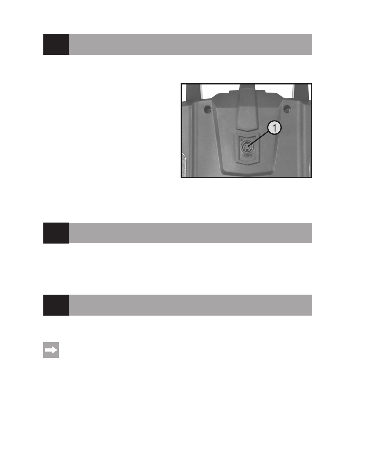
21. Simulator Function, Student Transmitter Function
If required, you can also use the transmitter at the PC for simulations or games. In this case, you will require the
optional USB cable (Conrad item no. 517956) and suitable computer software (e.g. ight simulation games, etc.).
The USB cable is connected to the PS2 interface socket
(16) at the rear of the transmitter.
At correct connection and proper installation, the activated
transmitter is recognised by the operating system (e.g. at
least Windows XP or higher) and can be used like a com-
mercial joystick.
For all further information on this, see the operating instructions of the USB cable.
Alternatively, the signal output of the remote control may
be used to control a teacher transmitter. In this case, the
remote control "HT-5" acts as the student transmitter.
Further information on this can be found in the operating
instructions of the teacher transmitter.
22. Maintenance and Care
Clean the exterior of the remote control with a soft, dry cloth or brush only. Never use abrasive cleaning agents or
chemical solutions as these could damage the surfaces of the casings.
23. Declaration of Conformity (DOC)
The manufacturer hereby declares that this product complies with the essential requirements and regulations and all
other relevant provisions of the 1999/5/EC directive.
The compliance statement for this product is available at www.conrad.com.
Figure 18
Page 26

26
24. Disposal
a) General Information
Electronic devices are recyclable and should not be disposed of in household waste.
At the end of its service life, dispose of the product according to the relevant statutory regulations.
Remove any inserted batteries/rechargeable batteries and dispose of them separately from the product.
b) Batteries and Rechargeable Batteries
You as the end user are required by law (Battery Ordinance) to return all used batteries/rechargeable batteries. Disposing of them in the household waste is prohibited!
Batteries and rechargeable batteries containing hazardous substances are marked with the adjacent sym-
bol to indicate that disposal in the household waste is prohibited. The descriptions for the respective heavy
metals are: Cd=cadmium, Hg=mercury, Pb=lead (the names are indicated on the battery/rechargeable battery e.g. below the rubbish bin symbol shown to the left).
You may return used batteries/rechargeable batteries free of charge at the ofcial collection points in your community,
in our stores, or wherever batteries/rechargeable batteries are sold.
You thus full your statutory obligations and contribute to the protection of the environment.
Page 27

27
25. Troubleshooting
Even though the remote control system was built to the state of the art, there can still be interference or faults. For this
reason, we would like to give you some information on how to deal with possible problems.
Problem Remedy
Transmitter doesn’t respond • Check the batteries in the transmitter.
• Check the polarity of the batteries.
• Check the battery contacts of the remote control.
• Check the on/off switch.
The servos do not respond • Check the transmitter function.
• Check the batteries in the receiver.
• Test the switch cable.
• Test the BEC function of the controller.
• Check the polarity of the servo connector.
• Check digital code.
• Perform binding.
• For test purposes, change the receiver and bind again.
The servos vibrate • Check batteries in the remote control and the receiver.
• Check connections on the receiver.
• Remove moisture in the receiver with a hair dryer in case it has gotten wet.
• Check the receiver aerial for damage.
• Reorient the receiver aerials in the model for test purposes.
One servo is humming • Check the batteries in the receiver.
• Make sure the linkage rods run smoothly.
• Operate the servo without the servo arm for test purposes.
The range of the system is
very short
• Check the batteries in the transmitter and receiver.
• Check the receiver aerial for damage.
• Install the receiver aerial in a different position in the model for test purposes.
Transmitter switches off on
its own at once of after a
short period
• Check the batteries in the transmitter and receiver.
Page 28

28
26. Technical Data
a) Transmitter
Frequency range ..................................2.4 GHz
Channel number ...................................5
Encoding ...............................................AFHDS / AFHDS2A (Automatic Frequency Hopping Digital System)
Signal output .........................................PS2 socket (PPM)
Operating voltage .................................6 V/DC via 4 type AA/mignon batteries
Dimensions (W x H x D) .......................174 x 187 x 80 mm
Weight without batteries .......................approx. 360 g
b) Receiver
Frequency range ..................................2.4 GHz
Channel number ...................................6
Encoding ...............................................AFHDS2A
Connector system .................................Graupner JR
Operating voltage .................................4.0 - 8.4 V/DC
Dimensions (W x H x D) .......................45 x 23.5 x 13.5 mm
Weight ..................................................Approx. 8 g
Page 29

29
Page 30

30
Page 31

31
Page 32

Legal Notice
This is a publication by Conrad Electronic SE, Klaus-Conrad-Str. 1, D-92240 Hirschau (www.conrad.com).
All rights including translation reserved. Reproduction by any method, e.g. photocopy, microlming, or the capture in electronic
data processing systems require the prior written approval by the editor. Reprinting, also in part, is prohibited. This publication
represent the technical status at the time of printing.
© Copyright 2016 by Conrad Electronic SE. V2_0416_01_DT
 Loading...