

Page 1
User Manual V1.0
Page 2

Congratulations on purchasing your new your
new X-220 racing drone.Please read this manual
carefully before using this product.
We recommend checking the following page
at www.conrad.com for news and updates for
product specs to manual updates. Due to ongoing
development, information contained in this manual
may change without prior notice.
If you have any question or concerns about your
product, please contact your local Conrad shops or
Conrad customer service.
Page 3

Contents
CONTENTS
Disclaimer & warning
In a box
1.0 Get to know your aircraft
2.0 Specifications
3.0 Attention before flight
4.0 Charge the battery
5.0 Assemble Aircraft
5.1 Propeller Installed
5.2 Battery Installed
6.0 Ready to fly
6.1 Binding
6.2 Motor Unlock/Lock
7.0 Operation Instruction
3-6
8
9
9
10
10
10
10
11
11
11
12-13
8.0 End flight
9.0 Additional remark
9.1 Remote controller menu operate
9.2 Remote controller system menu operate
9.3 Remote controller function menu operate
9.4 Remote controller notice
9.5 OSD Interface introduction
9.6 Power Board introduction
9.7 VTX introduction
2
13
14
14
14-17
17-18
18-19
20
20
21
Page 4

14
Disclaimer&Warning
and guidelines made available online or offline.
Conrad reserves
www.conrad.com for the
Product description
1.The performance of this product is dependent on original accessories and parts supplied. Conrad does
not undertake any maintenance obligation and or legal liability for the use of modified or non-original parts
and accessories.
2
3
Notice before using
3
Page 5

Airborne camera use matters needing attention
Notice for battery using and charging
Charging of Aircraft battery must only use the supplied battery charger.
Before flying,check battery is already install well
consequences could be severe.
other batteries of other specification to operate this model, otherwise, the
Limitation of liability
Conrad
4
Page 6

parts.
with modified or non-original accessories and
pilot
www.conrad.com.
www.conrad.com
not covered by the scope of this disclaimer due to improper operation,
maintenance and storage of equipment.
5
Page 7

WARNING
complies with the statutory national and European requirements.
The manufacturer
6
Page 8

In the box
Aircraft Remote Controller Propeller Pairs
X2
X2
User Manual
Motor Mount Mushroom Antenna
Battery Charger
14.8V 4S Li-Po
X4
7
Page 9

The chassis is created using CFP for outstanding crash survivability.
Modern industrial and modular design, improves the product performance
and permit easy maintainance and upgrades.
Advanced 5.8G live video, for an unforgeable visual FPV experience.
The X-220 employ a modern flight control system for acrobac flight
rounes such as roll, flip and race course moves.
1. Camera
2. ESC & ESC Cover
3. Motor Cover/ Landing Gear
4. Clockwise motor
5. Counterclockwise motor
6. Clockwise propeller
7. Counterclockwise propeller
8. 5.8GHz Video transmitter
9. Receiver
10. Flight Controller
11. Power panel
12. 14.8V 1300mAH 60C 4S Li-Po
13. LED lights ( Former Blue, Red after )
8
Page 10

Aircraft:
This aircraft is divided into two sizes
Main Rotor Dia: tri-blade propeller 4045/5045
Overall(L x W x H): 155x185x80mm/180x220x80mm
Weight: 340/355g (without Battery )
Remote Controller: FS-i6
Receiver: FS-i6x
Main Controller: SP Racing F3 Acro
Transmitter: FX795 25MV
Brushless Motor: 2205E-2300KV(CW/CCW)
Brushless ESC: 20A BLS
Battery: 14.8V 1300mAh 60C 4S Li-Po
Flight Time: 8Mins(4S Battery)
Working Temperature: -10C ~ + 40C
Camera
Horizontal Resolution: 800 TVL
System Committee: PAL/NTSC
Video Out: 1.0Vp - p/75Ω
Power Input: DC 5V
.
155mm/180mm
185mm/220mm
80mm
X-220
X-220
9
Page 11

Connect the power socket to an appropriate mains socket via the supplied power
cable. The Power LED lights up green when the charger is ready for operation.
Connect the rechargeable battery to be charged via its XH balancer plug with the
relevant jack of the charger. At that, observe the correct polarity of the XH plug.
When connecting, do not use excessive force; always use a socket matching the
jack. Only connect a single battery to the charger at a time. Always use only one
of the XH sockets at a time.
After a few seconds the LEDs 25%/75% and 50%/100% are flashing alternately.
This indicates that no rechargeable battery is connected and that the charger is
ready.Four LEDs on the charger indicate the charging status (25%, 50%, 75%
and 100%).Once the LED “100%” lights up, the battery is fully charged. Disconnect the battery from the charger.
LED
AC power cord
CW Propeller
(black nut)
Front
Fix the CW propeller onto the CW motor,
tighten the black propeller nuts anticlockwise.
Fix the CCW propeller onto the CCW motor,
tighten the blue propeller nuts clock wise.
Velcro already pre-attached on backside of battery pack and airframe. Simply place
battery on airframe while carefully observing and adjusting aircraft's center of gravity
while necessary.
Once aircraft gravity center, basic level, & head and tail are all correctly adjusted,
strap down battery with enclosed velcro belt to hold battery in place.
Grab the Air cr aft by the COG line
(center of gravity).See the illustration for the COG.
Adjust the battery f oward-backwards until the quad
balance.
CCW Propeller
(blue nut)
Propeller Spin Direction
Prop Nut Fasten This Direction
CCW Propeller
(blue nut)
CW Propeller
(black nut)
10
Page 12

Binding of the aircraft has default done before delivery, Please check
the details at P19 for the code way.
This product supports a key motor Unlock/lock, lock unlock, stir is the
motor lock key on the dial is the motor lock.
motor lock key
3
Mode key
Buzzer switch motor lock key
11
Page 13

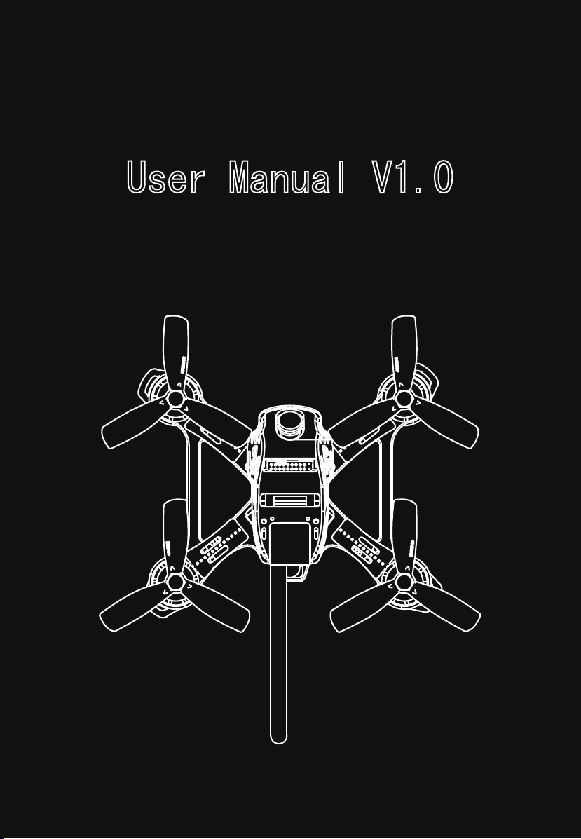
Aircraft Manual
Aircraft Up/Down
is head
Remote controller operating instruction
Tail towards yourself
Aircraft Forward/Backward
Aircraft stick to left/right
The level of the tail
The aircraft roll forward
Tail towards yourself
MODE 1 Right hand throttle stick MODE 2 Left hand throttle stick
MODE 2 Left hand throttle stickMODE 1 Right hand throttle stick
Mode key
1file for the gesture mode
2file for the Rolling mode
3file for the manual mode
Right hand throttle stick
The aircraft roll backward
Tail towards yourself
Attention:
1.) Always select open space without obstacles such as trees, fences or
buildings and make sure to keep a sufficiently safe distance from persons,
animals or objects during operation.
2.) If you do not have sufficient knowledge as to how to deal with remote
-controlled models, please seek the advice of an experienced model maker
or a model making club. Advance manuvers such as roll and flips are best
suited for experienced pilot only.
Left hand throttle stick
12
Page 14
Aircraft Manual
is head
Remote controller operating instruction
The aircraft roll left
The aircraft roll right
DREAM Baron AKA Proximity FPV obstacle flying
The mode key
Attention:
3.)The flight height of a racecopter is affected by the pitch function. Once the
control stick is in the centre position, the propeller speeds should be high
enough for the racecopter to hover. If the control stick is pushed forward further
, the racecopter will rise. If the control stick is pulled back, the racecopter drops.
Attention:
1.) Dream Baron is more suitable for experienced pilots,highspeed
obstacle avoidance flights requires advanced skills.
2.) Recommended FPV range 200m depending on environment.
3.)no liability is assumed for damage to property or personal injury
caused by improper use or the failure to observe the safety instructions!
In such cases the warranty/guarantee is voided.
1file for the gesture mode
2file for the Rolling mode
3file for the manual mode
Right/Left hand throttle stick
When battery voltage drops too low, buzzer alarm will sound regardless of buzzer switch
is on/ off. Please land aircraft as soon as possible to avoid accidents.
13
Page 15

Additional Remark
14
Page 16

15
Page 17

16
Page 18

17
Page 19

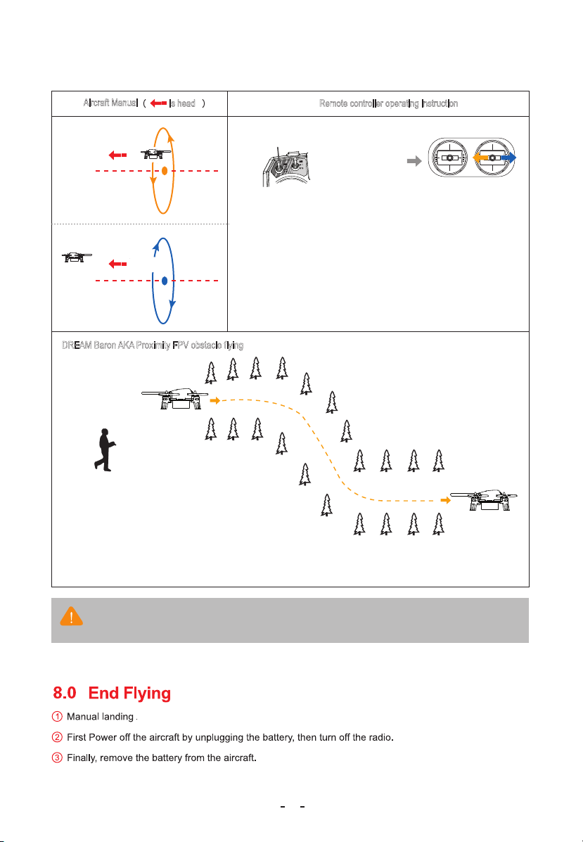
Very important notice:
All remote controller already adjust OK in factory.In normal,
donot to adjust any value. Especially reverse and endpoint.
Otherwise it will cause user cannot start motor.
18
Page 20
19
Page 21
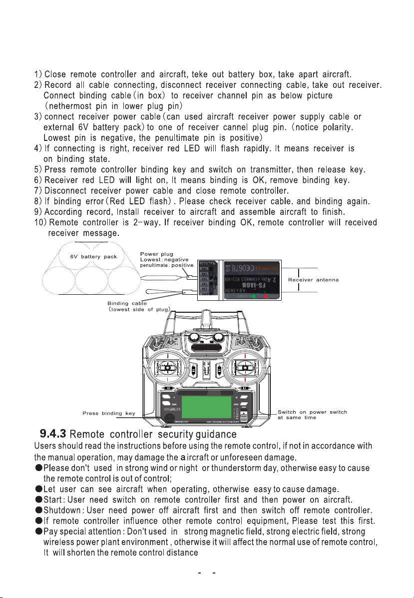
OSD Interface Instruction
Mode status
Attitude line
Volate indicate Current indicate
Drone operating time
User can set up the OSD interface by himself, you can add more info on the screen, can
show more flight data if the drone, as attitude , speed, direction, longitude&latitude,
distance between the take off point,etc.
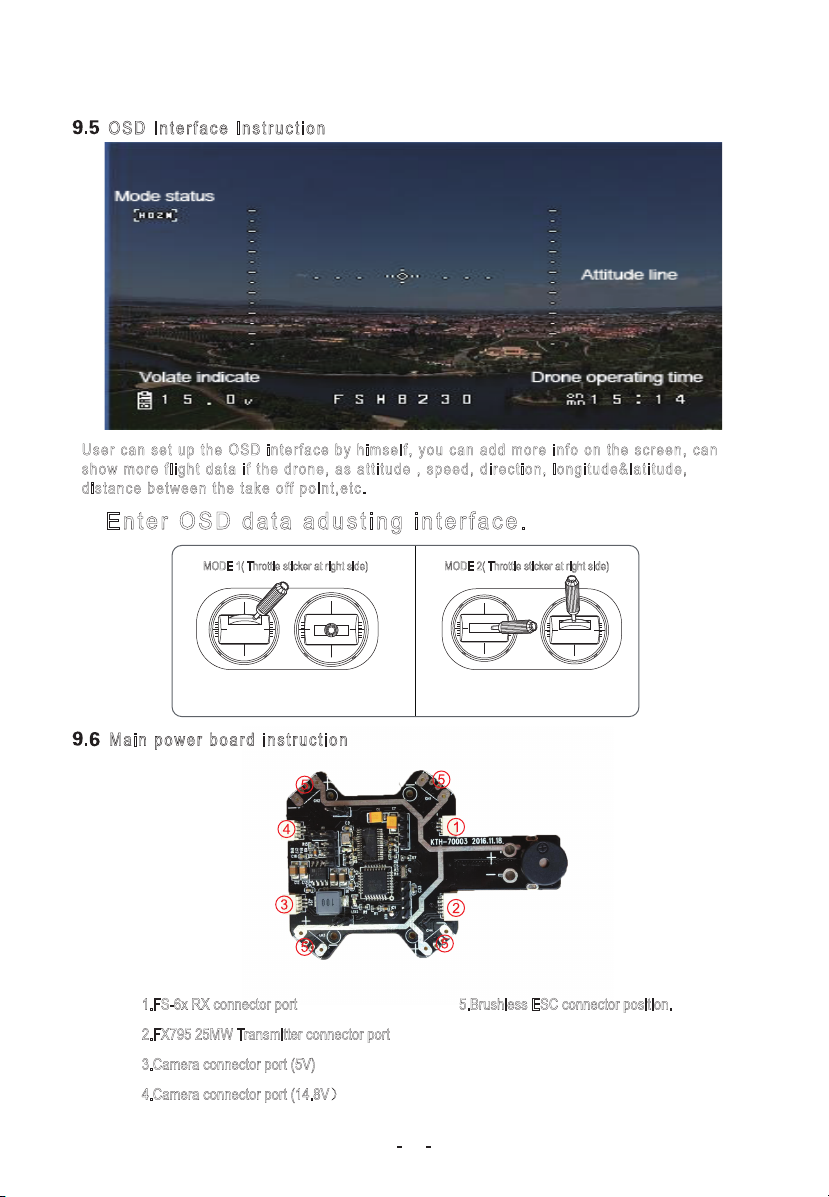
Enter OSD data adusting interface.
MODE 1( Throttle sticker at right side)
Main power board instruction
MODE 2( Throttle sticker at right side)
1.FS-6x RX connector port
2.FX795 25MW Transmitter connector port
3.Camera connector port (5V)
4.Camera connector port (14.8V)
5.Brushless ESC connector position.
20
Page 22
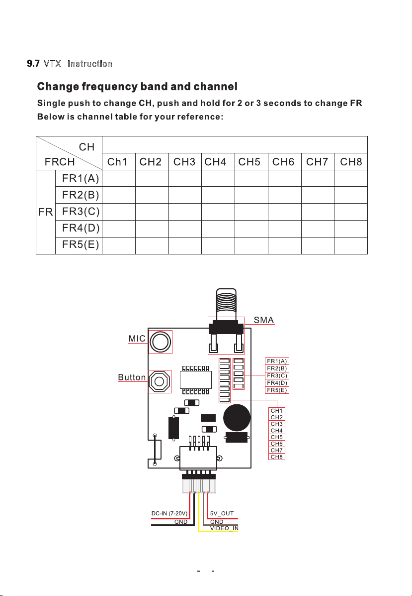
VTX Instruction
5740 5760 5780 5800 5820 5840 5860 5860
5740 5760 5780 5800 5820 5840 5860 5860
5865 5845 5825 5805 5785 5765 5745 5745
5732 5732 5732 5769 5806 5843 5843 5843
5733 5752 5771 5790 5809 5828 5847 5866
21
 Loading...