

Page 1
Version 02/09
GFK Rumpf Agusta 109 lackiert
Best.-Nr. 20 72 48
20 72 52
Bestimmungsgemäße Verwendung1.
Bei diesem Produkt handelt es sich um den Fiberglas-Rumpf eines Modell-Hubschraubers mit Fahrwerk und dazugehörigen
Reifen. Mit entsprechendem Zubehör kann das Gehäuse zu einem ugfertigen Modell aufgerüstet werden.
Aus Sicherheits- und Zulassungsgründen (CE) ist das eigenmächtige Umbauen und/oder Verändern des Produktes nicht gestattet.
Eine andere Verwendung als oben beschrieben ist nicht erlaubt und kann zur Beschädigung des Produkts führen. Darüber hinaus
ist dies mit Gefahren, wie z. B. Kurzschluss, Brand, Stromschlag usw. verbunden. Lesen Sie die Bedienungsanleitung genau
durch und bewahren Sie diese für späteres Nachschlagen auf.
Sicherheitshinweise2.
Bei Schäden, die durch Nichtbeachten dieser Bedienungsanleitung verursacht werden, erlischt die
Gewährleistung/Garantie! Für Folgeschäden übernehmen wir keine Haftung!
Bei Sach- oder Personenschäden, die durch unsachgemäße Handhabung oder Nichtbeachten der
Sicherheitshinweise verursacht werden, übernehmen wir keine Haftung. In solchen Fällen erlischt die
Gewährleistung/Garantie.
Wichtige Hinweise, die unbedingt zu beachten sind, werden in dieser Bedienungsanleitung durch das
Personensicherheit
Produktsicherheit
Sonstiges
Ausrufezeichen gekennzeichnet.
Das Produkt ist kein Spielzeug und nicht für Kinder unter 14 Jahren geeignet.•
Lassen Sie das Verpackungsmaterial nicht achtlos liegen, dieses könnte für Kinder zu einem gefährlichen Spielzeug werden.•
Das Produkt darf nicht feucht oder nass werden.•
Sollten Sie noch Fragen haben, die in dieser Bedienungsanleitung nicht beantwortet werden, so wenden Sie sich bitte an •
unseren technischen Kundendienst oder andere Fachleute.
Lieferumfang3.
GFK Rumpf •
Transparentes Kabinendach•
Aluminium-Fahrgestell•
Reifen•
Grau / grau-metallic
Rot / weiß / blau
Holzrahmengestell•
Befestigungsmaterial•
Bedienungsanleitung•
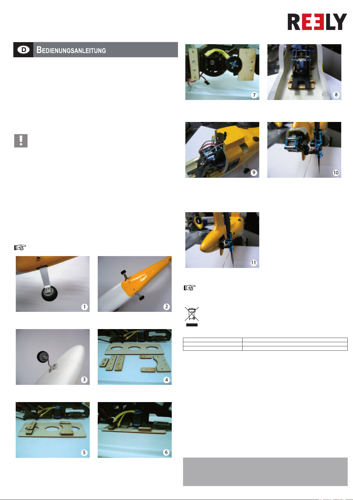
Nachdem alle Holzscheiben korrekt ausgerichtet wurden,
befestigen Sie die Holzscheiben mit den mitgelieferten
Schrauben. Kleben Sie die Holzscheiben nun mit
Epoxidkleber auf den Boden des Rumpfs.
Platzieren Sie den Hauptschaft in die Mitte der oberen
Öffnung und achten Sie darauf, dass er senkrecht steht.
Achten Sie ebenso darauf, dass die Taumelscheibe und
das Steuergestänge sich frei nach oben und unten bewegen
können. Nachdem die beste Position gefunden wurde,
kleben Sie den Hauptrahmen mit Epoxidkleber in den
Rumpf.
Mit entferntem hinterem Getriebe, testen Sie, ob die
Antriebseinheit in den Rumpf passt. Achten Sie darauf, dass
Teile nicht aneinander reiben oder sich biegen.
Setzen Sie das hintere Getriebe ein. Wir empfehlen,
ein wenig Schaumstoff um den Ausleger zu wickeln, um
Vibrationen zu dämpfen.
Zusammenbau4.
Bedienungsanleitung mit farbigen Bildern: www.conrad.com
Befestigen Sie zuerst das Hauptlandegestell mit den
mitgelieferten M3 Schrauben. Befestigen Sie dann die
Räder mit den Schrauben und Muttern M2.
Montieren Sie das Bugfahrgestell mit der Kunststoffklammer
und den Blechschrauben. Befestigen Sie dann das Bugrad
mit der Manschette.
Das fertige Hauptlandegestell sollte wie auf dem Bild
aussehen.
Legen Sie die Holzscheiben wie in dem Bild aus. Achten Sie
auf die Ausrichtung der Holzscheiben.
Befestigen Sie die Auslegerabdeckung mit den mitgelieferten
Schrauben. Achten Sie darauf, dass das Gestänge für den
Heckrotor nicht gebogen wird.
Wir empfehlen, die Hauptrotor und Heckrotorblätter vor dem Fliegen auszutarieren.
Entsorgung5.
Der Benutzer sollte nicht reparaturfähige Produkte gemäß den aktuell geltenden gesetzlichen Bestimmungen
entsorgen.
Technische Daten6.
Abmessungen (L x B x H): 750 x 115 x 225 mm
Material: GFK
Gewicht: 340 g
Montieren Sie die Holzscheiben wie in dem Bild. Montieren
Sie diese trocken, ohne Kleber. Extra-Holzscheiben sind
für die Höheneinstellung des Hauptrahmens in dem Rumpf
mitgeliefert. Achten Sie darauf, dass die Höhe gemäß dem
Heckausleger gewählt wird, um in die Mitte des Auslegers
zu passen.
Nachdem die korrekte Höhe eingestellt ist, richten Sie die
Holzscheiben an dem eigentlichen Befestigungspunkt für
das Landegestell aus.
Diese Bedienungsanleitung ist eine Publikation der Conrad Electronic SE,
Klaus-Conrad- Straße 1, D-92240 Hirschau.
Diese Bedienungsanleitung entspricht dem technischen Stand bei Drucklegung.
Änderungen in Technik und Ausstattung vorbehalten.
© 2009 by Conrad Electronic SE.
*02_02/09_01-SB
Page 2

Version 02/09
GRP Agusta 109 Fuselage, Varnished
Item no. 20 72 48
20 72 52
Intended Use1.
This product is the breglass fuselage of a model helicopter with undercarriage and wheels that go with it. The enclosure can be
upgraded to a model ready for ight with the appropriate accessories.
Unauthorised conversion and/or modication of the device are inadmissible because of safety and approval reasons (CE). Any
usage other than described above is not permitted and can damage the product and lead to associated risks such as short-circuit,
re, electric shock, etc. Please read the operating instructions thoroughly and keep them for further reference.
Safety instructions2.
We do not assume liability for resulting damages to property or personal injury if the product has been
abused in any way or damaged by improper use or failure to observe these operating instructions. The
warranty will then expire!
The icon with exclamation mark indicates important information in the operating instructions. Carefully
Personal safety
Product safety
Miscellaneous
read the whole operating instructions before operating the device, otherwise there is risk of danger.
The product is not a toy and should be kept out of reach of children under 14 years of age.•
Do not leave packaging material unattended. It may become a dangerous toy for children.•
The product must not get damp or wet.•
If any questions arise that are not answered in this operating instruction, contact our Technical Advisory Service or other experts.•
Delivery content3.
GRP fuselage•
Transparent canopy•
Aluminium undercarriage•
Tyres•
Grey / metallic grey
Red / white / blue
Wooden frame•
Mounting material•
Operating instructions•
Once all spacers are correctly aligned, mount the spacers
onto the main frame with the included screws. Afterward,
epoxy glue the spacer assembly onto the large base board.
Centre the main shaft in the top opening, and make sure it is
perpendicular to the body. Also, make sure the swash plate
and controlling rods can move up and down freely. Once
the best position is determined, epoxy glue the base board
assembly to the bottom of the body.
With the tail gear box removed, dry t the whole assembly
into the body. Make sure no rubbing or binding occours.
Install the tail rotor gear box. We recommend that you
wrap some foam padding around the tail boom to reduce
vibration.
Assembly4.
Manual with color pictures: www.conrad.com
First install the main landing gears with the supplied M3
screws and nut. Then install the wheel with the M2 nuts and
screws.
Install the nose gear with the plastic clamp and self tapping
screws. Then install the nose wheel with collar.
The nished main landing gears should look like this.
Arrange the wood spacers as in the photo. Please pay
attention to the direction of the spacer.
Install the tail rotor cover with the supplied screws. Make
sure there is no binding in the tail push rod.
We recommend that you balance the main and tail blades before ying your helicopter.
Disposal5.
The user should dispose unserviceable product in accordance with the current statutory regulations.
Technical data6.
Dimensions (L x W x H): 750 x 115 x 225 mm
Material: GRP
Gewicht: 340 g
Assemble the spacers as in the photo. Dry t only do not
glue. Extra spacers are included for adjusting the height
of main frame in the fuselage. Note the height should be
adjusted to t the tail boom in the certer of the fuselage’s
tail section.
Once the correct height is determined, align the spacers to
your helicopter’s original mounting point for landing gears.
These operating instructions are published by Conrad Electronic SE,
Klaus-Conrad-Straße 1, D-92240 Hirschau/Germany.
The operating instructions reect the current technical specications at time of print.
We reserve the right to change the technical or physical specications.
© 2009 by Conrad Electronic SE.
*02_02/09_01-SB
Page 3

Version 02/09
Fuselage en composite verre résine
d’Agusta 109 verni
Nº de commande 20 72 48 Gris/ gris métallisé
20 72 52 Rouge / blanc / bleu
Utilisation prévue1.
Ce produit est le fuselage en bre de verre d’une maquette d’hélicoptère avec son train d’atterrissage et les pneus correspondants.
Avec les accessoires adaptés, il est possible de faire de cette carlingue une maquette prête à voler.
La conversion et/ou la modication non autorisées de l’appareil ne sont pas permises pour des raisons de sécurité et d’approbation
(CE). Tout usage autre que celui décrit ci-dessus est interdit, peut endommager le produit et poser des risques tels que courtscircuits, incendies, chocs électriques, etc. Prière de lire attentivement le mode d’emploi et de le conserver à titre de référence.
Consignes de sécurité2.
Nous déclinons toute responsabilité en cas de dommages matériels ou de blessures dans le cas où
cet appareil aurait été maltraité de quelque façon que ce soit ou endommagé du fait d’une mauvaise
utilisation ou d’un non respect de ce mode d’emploi. La garantie en serait d’ailleurs annulée!
Le point d’exclamation attire l’attention sur une information importante dont il convient de tenir compte
Ce produit n´est pas un jouet, maintenez-le hors de la portée des enfants.•
Ne laissez pas le matériel d’emballage sans surveillance ; il pourrait constituer un jouet dangereux pour les enfants.•
Le produit ne doit pas être humidié, ni mouillé.•
Si vous avez des questions sur un point non abordé dans ce mode d’emploi, contactez notre service technique ou autres •
experts.
Contenu d’emballage3.
Fuselage en composite verre résine•
Toit de l’habitacle transparent•
Train d’atterrissage en aluminium•
Pneus•
impérativement.
Châssis en bois•
Matériel de xation•
Instructions d’utilisation•
Sécurité personnelle
Sécurité du produit
Divers
Assemblez les cales d’espacement comme sur l’illustration.
Positionnez à sec. Ne pas coller ! Des cales d’espacement
supplémentaires sont incluses pour permettre d’ajuster la
hauteur du cadre principal dans le fuselage. Notez que la
hauteur doit être ajustée pour s’adapter à la poutre arrière
dans la partie centrale de l’empennage du fuselage.
Une fois que toutes les cales d’espacement sont
correctement alignées, montez les dites cales sur le cadre
principal avec les vis fournies. Ensuite, collez avec la glu
l’assemblage des cales sur le grand panneau de base.
Une fois que la bonne hauteur est déterminée, alignez les
cales d’espacement sur le point de montage original pour
trains d’atterrissage de votre hélicoptère.
Avec la boîte de transmission arrière enlevée, positionnez
tout l’assemblage dans le corps de l’appareil.
Assurez-vous qu’il n’y ait aucun frottement ou contact.
Assemblage4.
Mode d’emploi avec des images en couleur: www.conrad.com
Installez d’abord les principaux trains d’atterrissage à l’aide
des vis et écrous M3 fournis. Ensuite, xez la roue avec les
écrous et vis M2.
Installez le train avant avec l’attache en plastique et vis
autotaraudeuses. Ensuite, installer la roue avant avec le collier.
L’installation du train d’atterrissage principal devrait
ressembler à l’illustration.
Disposer les cales d’espacement en bois comme sur l’illustration.
Veuillez faire attention à la direction des cales d’espacement.
Centrez donc l’axe principal dans l’ouverture du haut et
assurez-vous qu’il est perpendiculaire au corps de l’appareil.
Assurez-vous aussi que le plateau oscillant et les barres de
contrôle puissent bouger librement de bas en haut. Une fois
que la meilleure position est déterminée, collez avec de la
glu l’assemblage du panneau de base sur le fond du corps
de l’appareil.
Installez le capot du rotor avec les vis fournies. Assurezvous que la barre de liaison de la commande soit libre.
Nous vous recommandons d’équilibrer les pales principales et arrières avant de faire voler votre hélicoptère.
Installez la boîte de transmission arrière. Nous vous
recommandons d’enrouler autour de la poutre arrière un
rembourrage en mousse an de réduire les vibrations.
Elimination des déchets5.
L’utilisateur doit mettre au rebut les produits non réutilisables conformément à la réglementation en vigueur.
Caractéristiques techniques6.
Dimensions (L x I x H) : 750 x 115 x 225 mm
Matière : Composite verre résine
Poids : 340 g
Cette notice est une publication de la société Conrad Electronic SE,
Klaus-Conrad-Straße 1, D-92240 Hirschau/Allemagne.
Cette notice est conforme à la réglementation en vigueur lors de l´impression.
Données techniques et conditionnement soumis à modications sans aucun préalable.
© 2009 par Conrad Electronic SE.
*02_02/09_01-SB
Page 4

Versie 02/09
GFK romp Agusta 109 gelakt
Bestnr. 20 72 48 Grijs / grijs metallic
20 72 52 Rood / wit / blauw
Bedoeld gebruik1.
Bij dit product gaat het om een glasvezelromp van een modelhelikopter met onderstel en daarbij behorende banden. Met het
juiste toebehoren kan van de behuizing een vliegklaar model worden gemaakt.
Het eigenhandig ombouwen en/of veranderen van het product is niet toegestaan om veiligheids- en keuringsredenen (CE). Een
andere toepassing dan hierboven beschreven, is niet toegestaan en kan leiden tot beschadiging van het product. Daarnaast
bestaat het risico van bijv. kortsluiting, brand, elektrische schokken, enz. Lees de gebruiksaanwijzing grondig door en bewaar
deze voor raadpleging in de toekomst.
Veiligheidsinstructies2.
Wij zijn niet verantwoordelijk voor schade aan eigendom of lichamelijke letsels indien het product
verkeerd gebruikt werd op om het even welke manier of beschadigd werd door het niet naleven van deze
bedieningsinstructies. De waarborg vervalt dan!
Het uitroepteken geeft belangrijke informatie aan voor deze bedieningsinstructies waaraan u zich strikt
Persoonlijke veiligheid
Productveiligheid
Diversen
moet houden.
Het product is geen speelgoed. Het is niet geschikt voor kinderen onder de 14 jaar.•
U mag het verpakkingsmateriaal niet zomaar laten rondslingeren. Dit is gevaarlijk speelgoed voor kinderen.•
Het product mag niet vochtig of nat worden.•
Voor vragen waarop deze gebruiksaanwijzing geen antwoord biedt, kunt u contact opnemen met onze technische dienst •
of andere specialisten.
Leveringsomvang3.
GFK romp•
Transparant cabinedak•
Aluminium landingsgestel•
Banden•
Gestel met houten frame•
Bevestigingsmateriaal•
Gebruiksaanwijzing•
Voeg de spacers samen zoals weergegeven op de foto. Leg
ze op elkaar, lijm ze niet vast. Extra spacers zijn bijgeleverd
voor het regelen van de hoogte van het interne skelet in de
romp. Zorg er daarbij voor dat de hoogte zo is ingesteld dat
de staartas in het midden van het staartstuk van de romp
uitkomt.
Bevestig de spacers, als ze goed uitgelijnd zijn, aan het
interne skelet met behulp van bijgeleverde schroeven. Lijm
daarna de geassembleerde spacers met epoxylijm vast aan
de grote bodemplaat.
Plaats, als de juiste hoogte is ingesteld, de spacers waarbij
U de bevestigingspunten van het landingsgestel als
referentiepunt neemt.
Verwijder de tandwielkast van de staartrotor en plaats de
motoropbouw in de romp. Zorg ervoor dat niets aanloopt of
vast kan gaan zitten.
Samenscholing4.
Gebruiksaanwijzing met kleuren foto's: www.conrad.com
Monteer eerst het hoofdlandingsgestel met behulp van de
bijgeleverde M3 bouten en moeren. Bevestig dan de wielen
eraan met behulp van de M2 bouten en moeren.
Bevestig het neuswiel met behulp van de plastic klem en de
zelftappende schroeven. Installeer dan het neuswiel met ens.
Hierna moet het hoofdlandingsgestel er uitzien zoals op de
foto te zien is.
Leg de houten spacers neer zoals op de foto getoond wordt.
Let er daarbij goed op dat de spacers goed liggen.
Centreer de hoofdaandrijfas in de bovenste opening en zorg
ervoor dat die as loodrecht op de romp staat. Zorg er ook
voor dat de tuimelschijf en de controlestangen ongehinderd
op en neer kunnen bewegen. Lijm, zodra de optimale positie
bepaald is, de hele motoropbouw met epoxylijm vast aan de
onderkant van de romp.
Installeer de staartkap en maak hem vast met bijgeleverde
schroeven. Zorg ervoor dat de stuurstang voor de staart vrij
blijft.
Wij bevelen u aan de hoofd- en de staartrotorbladen uit te balanceren voordat u de helikopter laat vliegen.
Installeer de tandwielkast van de staartrotor. Wij raden U
aan schuimrubber om de staartas te wikkelen om eventuele
trillingen te reduceren.
Verwijdering5.
De gebruiker dient niet-repareerbare producten te verwijderen volgens de voorgeschreven richtlijnen.
Technische gegevens6.
Afmetingen (L x B x H): 750 x 115 x 225 mm
Materiaal: GFK
Gewicht: 340 g
Deze gebruiksaanwijzing is een publicatie van Conrad Electronic SE,
Klaus-Conrad-Straße 1, D-92240 Hirschau/Duitsland.
Deze gebruiksaanwijzing voldoet aan de technische eisen bij het ter perse gaan.
Wijzigingen in techniek en uitrusting voorbehouden.
© 2009 bei Conrad Electronic Benelux B.V.
*02_02/09_01-SB
 Loading...