

Page 1

Bedienungsanleitung Version 11/12
Allrad-Umrüstsatz
Best.-Nr. 23 59 28
Best.-Nr. 23 71 97
Best.-Nr. 51 70 44
Bestimmungsgemäße Verwendung
Das Produkt dient dem Umbau von Modellfahrzeugen der Carbon-Fighter-Serie von Heckantrieb (2WD) auf Allradantrieb (4WD). Da es verschiedene Modelle in der genannten Serie gibt,
sind auch drei unterschiedliche Nachrüstsätze erhältlich. Zudem sind teilweise bei der
Modellpflege unterschiedliche Komponenten (z.B. Differenziale) verbaut worden.
Daher zeigt die vorliegende Einbauanleitung nur den allgemeinen, systematischen Einbau
des 4WD-Nachrüstsatzes und dient somit nur der Illustration der erforderlichen Arbeitsschritte.
Die aufgezeigten Arbeitsschritte sind bei allen Modellen identisch, die Anzahl und Lage der
betroffenen Schrauben ist jedoch unterschiedlich und muss individuell je nach Modell nach
eigenem Ermessen berücksichtigt werden.
Weitere Informationen, welcher Nachrüstsatz in welches Modell eingebaut werden kann,
finden Sie in unseren Katalogen oder unter www.conrad.com beim jeweiligen Produkt.
Dieses Produkt erfüllt die gesetzlichen, nationalen und europäischen Anforderungen. Alle
enthaltenen Firmennamen und Produktbezeichnungen sind Warenzeichen der jeweiligen
Inhaber. Alle Rechte vorbehalten.
Zum Umbau werden Werkzeuge wie Innnensechskantschlüssel sowie Schraubendreher in verschiedenen Größen benötigt. Zudem benötigen Sie Schraubensicherheitslack und Schmierfett. Passendes Zubehör finden Sie in unseren Katalogen und unter www.conrad.com.
Sicherheitshinweise
Bei Schäden, die durch Nichtbeachten dieser Bedienungsanleitung verursacht werden, erlischt die Gewährleistung/Garantie! Für Folgeschäden übernehmen wir keine Haftung!
Bei Sach- oder Personenschäden, die durch unsachgemäße Handhabung
oder Nichtbeachten der Sicherheitshinweise verursacht werden, übernehmen wir keine Haftung! In solchen Fällen erlischt die Gewährleistung/Garantie.
• Aus Sicherheitsgründen ist das eigenmächtige Umbauen und/oder Verändern des Produktes nicht gestattet.
• Das Produkt ist kein Spielzeug und gehört nicht in Kinderhände.
• Beachten Sie im Umgang mit Werkzeug auf die erhöhte Verletzungsgefahr.
• Entleeren Sie vor dem Umbau den Tank Ihres Modells.
• Aus sicherheitstechnischen Gründen müssen Sie nach dem Umbau alle Schraubverbindungen auf einen korrekten, festen Sitz prüfen.
• Bei Schraubverbindungen „Metall/Metall“ muss zwingend Schraubensicherungslack verwendet werden.
• Überprüfen Sie die korrekte Funktion aller Fernsteuerelemente.
• Lassen Sie das Verpackungsmaterial nicht achtlos liegen; dieses könnte für Kinder zu einem
gefährlichen Spielzeug werden.
Einbau des 4WD-Nachrüstsatzes
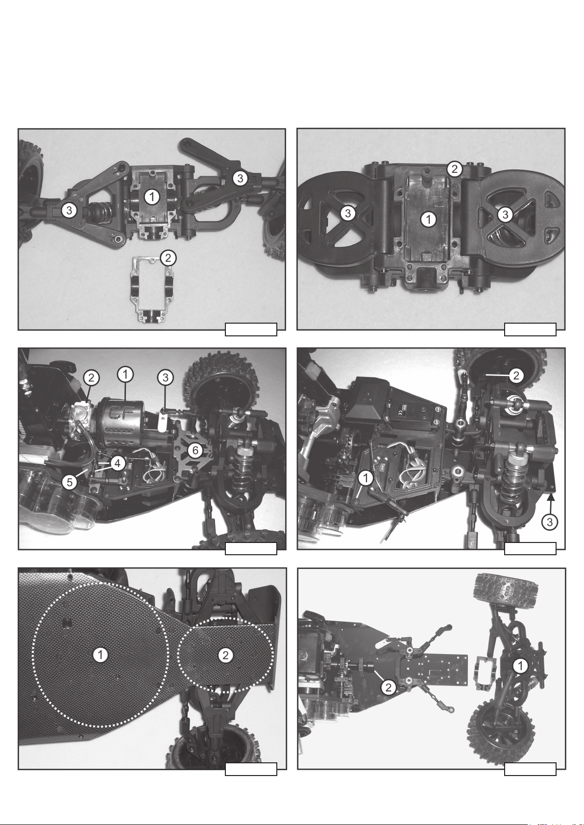
Bild 1 und Bild 2:
Bei den Fahrzeugen der Carbon-Serie wurden unterschiedliche Differenziale verbaut. Der Umrüstsatz Conrad-Best.-Nr. 235928+237197 kann nur bei den Modellen
eingebaut werden, bei denen die unteren Querlenker der Vorderachse (Bild 1, Pos.
3) am Chassis angeschraubt sind. In Bild 1 sehen Sie das obere Differenzialgehäuse
(1) und das untere Differenzialgehäuse (2).
Der Umrüstsatz Conrad Best.-Nr. 517044 kann nur bei den Modellen eingebaut
werden, bei denen die unteren Querlenker der Vorderachse am vorderen (leeren)
Differentialgehäuse angeschraubt sind (Bild 2). In Bild 2 sehen Sie das obere
Differenzialgehäuse (1) und das untere Differenzialgehäuse (2) mit angeschraubten
Querlenkern (3).
Arbeitsschritte zu Bild 3:
• Entfernen Sie die Karosserie + Überrollbügel vom Modell.
• Entfernen Sie den Luftfilter (1) und den Vergaser (2), hängen Sie das Gasgestänge aus.
• Entfernen Sie den Servohebel des Lenkservos (3).
• Lösen Sie die Innensechskantschraube der Bremsmechanik (4) und ziehen den Bremshebel ab.
• Entfernen Sie die vordere und hintere Metallplatte (5 und 6).
Arbeitsschritte zu Bild 4:
• Entfernen Sie eventuell noch an der Oberseite vorhandene Befestigungsschrauben der RCBox (1).
• Entfernen Sie die Schrauben der beiden Achsschenkel (2).
• Entfernen Sie den Rammschutz (3).
Arbeitsschritte zu Bild 5:
• Entfernen Sie alle Schrauben auf der Unterseite des Chassis, die zur Befestigung der RCBox dienen (1).
• Entfernen Sie alle Schrauben auf der Unterseite des Chassis, die zur Befestigung des
vorderen Differenzials dienen. Sind die unteren Querlenker der Vorderachse am Chassis
befestigt, so müssen diese ebenfalls entfernt werden.
Arbeitsschritte zu Bild 6:
• Entfernen Sie die komplette Vorderachsen-Einheit vom Chassis (1).
• Montieren Sie den Wellenmitnehmer aus dem Set auf der Abtriebswelle (2). Verwenden Sie
für die Befestigungsschraube des Wellenmitnehmers Schraubensicherungslack.
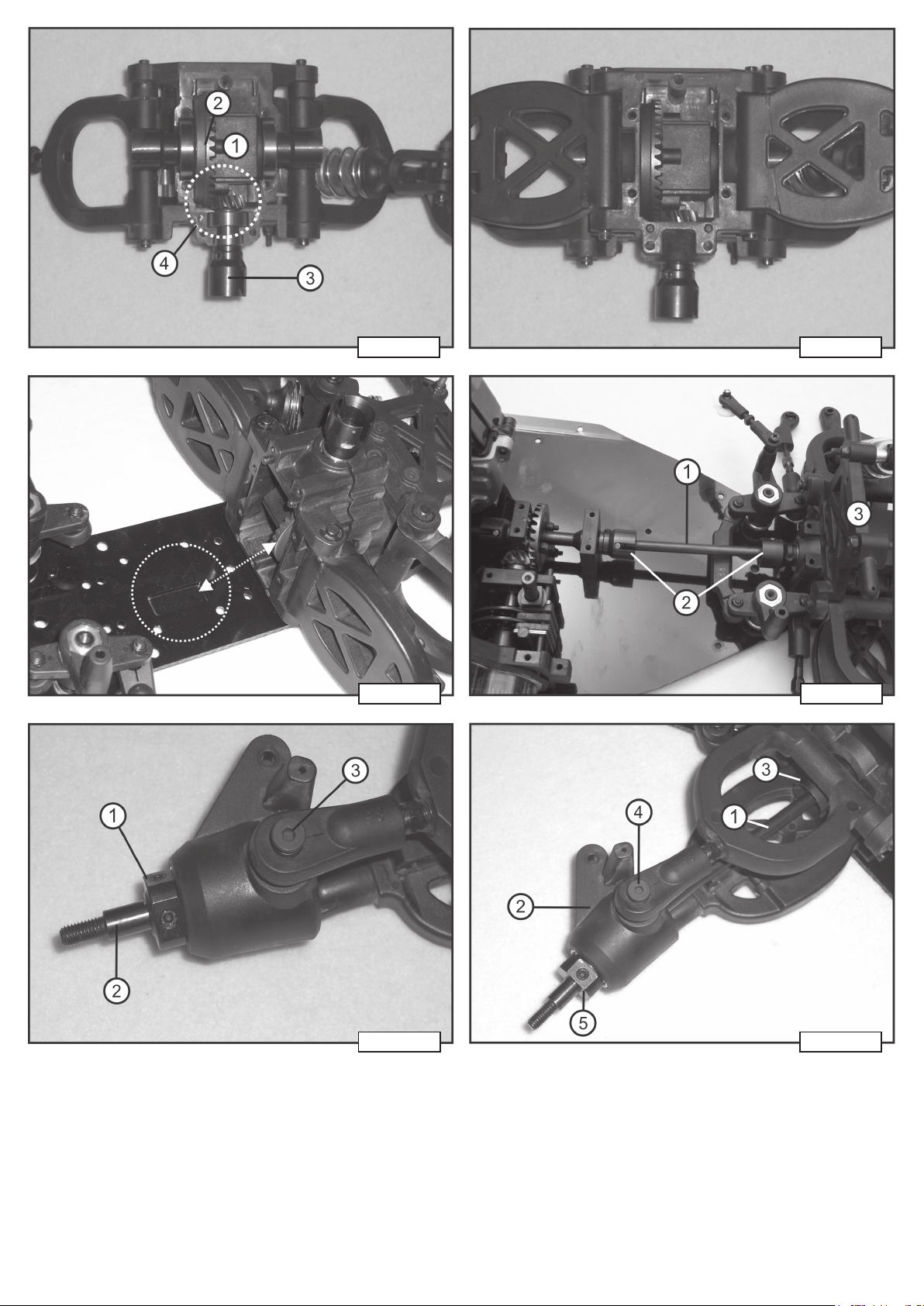
Arbeitsschritte zu Bild 7, 8, 9:
• Setzen Sie das Differenzial (1) aus dem Set in das obere Differenzialgehäuse. Das große
Zahnrad (2) muss so positioniert werden, damit das Zahnrad in der entsprechenden
Vertiefung der Chassisplatte frei laufen kann (siehe auch Bild 9 bzw. individuell bei Ihrem
Modell beachten).
• Setzen Sie das kleine Zahnrad (3) aus dem Set in das Differenzialgehäuse ein.
• Geben Sie auf die Zahnräder reichlich Schmierfett und füllen die Seite beim großen Zahnrad
satt auf (4). Das Differenzialgehäuse muss an dieser Stelle dann gut zur Hälfte gefüllt sein,
um einen dauerhaften Schmierfilm zu gewährleisten.
• In Bild 7 sehen Sie die Montage des Differenzials in das obere Differenzialgehäuse. In Bild
8 sehen Sie das montierte Differenzial bei aufgesetztem unteren Differenzialgehäuse
(gezeigt wird die Differenzial-Variante mit montierten Querlenkern). In Bild 9 sehen Sie ein
Beispiel einer Vertiefung der Chassisplatte im Bereich des vorderen Differenzials.
Arbeitsschritte zu Bild 10:
• Montieren Sie die Abtriebswelle aus dem Set (1) zwischen den Wellenmittnehmern (2).
• Schrauben Sie die Vorderachse (3) am Chassis fest. Achten Sie darauf, dass die Montage
zu keinen Verspannungen im Chassis sowie im Antriebsstrang (Welle) führt.
Arbeitsschritte zu Bild 11:
• Demontieren Sie die vorderen Räder.
• Entfernen Sie die Rad-Mitnehmer (1) von beiden Achsen (2). Der Mitnehmer hat zwei
unterschiedliche Seiten; achten Sie deshalb vor der Demontage genau darauf, wie der
Mitnehmer montiert war!
• Entfernen Sie die obere und untere Schrauben der beiden Achsschenkel (3).
• Entfernen Sie die beiden Achsen (2) aus den Achsschenkeln.
Arbeitsschritte zu Bild 12:
• Montieren Sie die beiden Antriebswellen aus dem Set (1) in den Achsschenkeln (2) und
stecken die Antriebswellen in die Mitnehmer des Differenzials (3).
• Schrauben Sie die Achsschenkel wieder fest (4).
• Montieren Sie die Rad-Mitnehmer auf die Wellen (5). Beachten Sie die richtige Montage der
Mitnehmer (siehe „Arbeitsschritte zu Bild 11).
• Montieren Sie die Räder wieder.
Der Umbau von Heckantrieb (2WD) auf Allradantrieb (4WD) ist hiermit beendet.
Bauen Sie in umgekehrter Reihenfolge die RC-Box, den Vergaser und den Luftfilter wieder
ein. Achten Sie auf den korrekten, festen Sitz der Bauteile.
Nach dem Vergasereinbau muss die Beweglichkeit des Choke-Hebels geprüft werden. Ist der
Chokehebel nicht oder nur schwergängig zu betätigen, muss der Vergaser etwas gelockert
und nochmals zentriert werden. Überprüfen Sie vor der ersten Fahrt auch die korrekte
Funktion der Fernsteuerung.
Diese Bedienungsanleitung ist eine Publikation der Conrad Electronic SE, Klaus-Conrad-Str. 1,
D-92240 Hirschau (www.conrad.com).
Alle Rechte einschließlich Übersetzung vorbehalten. Reproduktionen jeder Art, z. B. Fotokopie,
Mikroverfilmung, oder die Erfassung in elektronischen Datenverarbeitungsanlagen, bedürfen der
schriftlichen Genehmigung des Herausgebers. Nachdruck, auch auszugsweise, verboten.
Diese Bedienungsanleitung entspricht dem technischen Stand bei Drucklegung. Änderung in Technik
und Ausstattung vorbehalten.
© Copyright 2012 by Conrad Electronic SE. V1_1112_01
Page 2

Operating Instructions Version 11/12
All-Wheel Retrofitting Set
Item no. 23 59 28
Item no. 23 71 97
Item no. 51 70 44
Intended Use
The product serves to retrofit model vehicles of the Carbon-Fighter series from rear-wheel
drive (2WD) to four-wheel drive (4WD). Since the series has several models, three different
kits for retrofitting are available as well. Additionally, different components may have been
installed during model maintenance (e.g. differentials).
Therefore, the present installation instructions only show the general systematic installation
of the 4WD retrofitting kit. It only serves to illustrate the required steps.
The indicated work steps are identical for all models. The number and position of the affected
screws, however, differs and must be individually considered according to model and own
discretion.
For more information on which retrofitting kit can be installed in which model, see our
catalogues or the respective product at www.conrad.com.
This product complies with the statutory national and European requirements. All company
names and product names are trademarks of their respective owners. All rights reserved.
Conversion requires tools like Allen keys and screwdrivers in various sizes. You also
require threadlocker varnish and grease. See our catalogues and our website at
www.conrad.com for matching accessories.
Safety Information
The guarantee/warranty will expire if damage is incurred resulting from noncompliance with the operating instructions! We do not assume any liability
for consequential damage!
We do not assume any liability for damage to property or personal injury
caused by improper use or the failure to observe the safety instructions! In
such cases the warranty/guarantee will expire.
• For safety reasons, any unauthorized conversions and/or modifications to the product are
not permitted.
• This product is not a toy and not suitable for children.
• Observe the increased danger of injury when handling tools.
• Empty your model’s tank before conversion.
• For safety-technical reasons, check all screw connections for correct and tight seat after
conversion.
• Always use threadlocker varnish for „metal/metal“ screw connections.
• Check correct function of all remote control elements.
• Do not leave the packaging material lying around carelessly since such materials can
become dangerous toys in the hands of children.
Work steps for figure 4:
• Remove any attachment screws of the RC box (1) that may still be present at the top.
• Remove the screws of both steering knuckles (2).
• Remove the skirting protection (3).
Work steps for figure 5:
• Remove all screws at the bottom of the chassis that serve to attach the RC box (1).
• Remove all screws at the bottom of the chassis that serve to attach the front differential. If
the lower transverse links of the front axle are attached to the chassis, they must be removed
as well.
Work steps for figure 6:
• Remove the complete front axle unit from the chassis (1).
• Install the shaft tappet from the set on the output shaft (2). Use threadlocker varnish for the
attachment screw of the shaft tappet.
Work steps for figures 7, 8, 9:
• Place the differential (1) from the set into the upper differential housing. The large cogwheel
(2) must be placed so that the cogwheel can run freely in the corresponding recess of the
chassis plate (also see figure 9 or individual placement in your model).
• Insert the small cogwheel (3) from the set into the differential housing.
• Apply grease on the cogwheels generously and fill the side at the large cogwheel until
saturated (4). The differential housing must be filled to about half in this place to warrant a
lasting lubrication film.
• Figure 7 shows assembly of the differential into the upper differential housing. Figure 8
shows the installed differential with attached lower differential housing (the illustration shows
the differential version with installed transverse links). Figure 9 shows an example of an
indentation of the chassis plate in the area of the front differential.
Work steps for figure 10:
• Install the output shaft from the set (1) between the shaft tappets (2).
• Screw the front axle (3) to the chassis. Ensure that assembly does not cause tension in the
chassis and the drive strain (shaft).
Work steps for figure 11:
• Disassemble the front wheels.
• Remove the wheel tappets (1) from both axles (2). The tappet has two different sides;
therefore, note how the tappet is installed before disassembling it!
• Remove the top and bottom screws of of both steering knuckles (3).
• Remove the two axles (2) from the steering knuckles.
Work steps for figure 12:
• Install the two drive shafts from the kit (1) in the steering knuckles (2) and push the drive
shafts into the tappets of the differential (3).
• Screw on the steering knuckles again (4).
• Install the wheel tappets on the shafts (5). Observe correct installation of the tappets (see
„Work steps for figure 11).
• Install the wheels again.
Conversion from rear-wheel drive (2WD) to all-wheel drive (4WD) hereby is completed.
Install the RC box, carburettor and air filter again in reverse order. Make sure that the
components are placed correctly and firmly.
After installation of the carburettor, the movability of the choke lever must be verified. If the
choke lever cannot be operated or if it is difficult to operate, the carburettor must be loosened
and centred again. Check that the remote control is working correctly before every operation.
Installation of the 4WD Retrofitting Kit
Figures 1 and 2:
Different differentials have been installed in the Carbon series vehicles. The
retrofitting kit Conrad item no. 235928+237197 can only be installed in the models
in which the lower transverse links of the front axle (figure 1, item 3) are screwed to
the chassis. Figure 1 shows the top differential housing (1) and the lower differential
housing (2).
The retrofitting kit Conrad item no. 517044 can only be installed in the models in
which the lower transverse links of the front axle are screwed to the front (empty)
differential housing (figure 2). Figure 2 shows the top differential housing (1) and the
lower differential housing (2) with screwed-on transverse links (3).
Work steps for figure 3:
• Remove the car body + over-roll bars from the model.
• Remove the air filter (1) and the carburettor (2), disconnect the throttle linkage.
• Remove the servo lever of the steering servo (3).
• Loosen the hexagon socket screw of the braking mechanics (4) and remove the braking
lever.
• Remove the front and rear metal plates (5 and 6).
These operating instructions are a publication by Conrad Electronic SE, Klaus-Conrad-Str. 1,
D-92240 Hirschau (www.conrad.com).
All rights including translation reserved. Reproduction by any method, e.g. photocopy, microfilming,
or the capture in electronic data processing systems require the prior written approval by the editor.
Reprinting, also in part, is prohibited.
These operating instructions represent the technical status at the time of printing. Changes in
technology and equipment reserved.
© Copyright 2012 by Conrad Electronic SE.
Page 3

Notice d’emploi Version 11/12
Kit de conversion traction intégrale
N° de commande 23 59 28
N° de commande 23 71 97
N° de commande 51 70 44
Utilisation conforme
Le produit a été conçu pour la conversion de la traction arrière (2WD) en traction intégrale
(4WD) de modèles réduits de véhicules de la série « Carbon Fighter ». Comme cette série
comporte plusieurs modèles réduits, trois différents kits de conversion sont disponibles. Par
ailleurs, il est possible que différents composants aient été ajoutés pendant l’entretien du
modèle réduit (par ex. différentiels).
C’est la raison pour laquelle la présente notice de montage ne montre que le montage général
et systématique du kit de conversion 4WD et n’est fournie qu’en vue de l’illustration des étapes
requises.
Les étapes décrites sont identiques pour tous les modèles réduits, la quantité et la position des
vis concernées varient cependant d’un modèle réduit à l’autre, pensez-y.
Pour de plus amples informations à propos de la compatibilité des différents kits de conversion
et modèles réduits, consultez nos catalogues ou la rubrique correspondante du produit sur
notre site web www.conrad.com.
Ce produit est conforme aux exigences légales, nationales et européennes. Tous les noms
d’entreprises et appellations de produits contenus dans ce mode d’emploi sont des marques
déposées des propriétaires respectifs. Tous droits réservés.
Pour la conversion, employer des outils comme une clé mâle coudée pour vis à six
pans creux et des tournevis de différentes tailles. Vous aurez également besoin de
vernis de blocage liquide et de la graisse. Les accessoires assortis sont disponibles
dans nos catalogues et sur le site web www.conrad.com.
Consignes de sécurité
Tout dommage résultant d’un non-respect du présent mode d’emploi entraîne
l’annulation de la garantie ! Nous déclinons toute responsabilité pour les
dommages consécutifs !
De même, nous n’assumons aucune responsabilité en cas de dommages
matériels ou corporels résultant d’une utilisation de l’appareil non conforme
aux spécifications ou du non-respect des présentes consignes de sécurité !
De tels cas entraînent l’annulation de la garantie ou garantie légale.
• Pour des raisons de sécurité, il est interdit de transformer et / ou modifier le produit de
manière arbitraire.
• L’appareil n’est pas un jouet, le tenir hors de portée des enfants.
• Compte tenu du danger de blessures accru, soyez particulièrement prudent durant la
manipulation des outils.
• Avant la conversion, videz le réservoir de votre modèle réduit.
• Pour des raisons de sécurité technique, vous devez vous assurer du serrage correct de tous
les raccords vissés après la conversion.
• Les assemblages par vis « métal sur métal » doivent impérativement être protégés à l’aide
de vernis de blocage liquide.
• Assurez-vous du fonctionnement correct de tous les éléments de la télécommande.
• Ne laissez pas le matériel d’emballage sans surveillance, il pourrait constituer un jouet
dangereux pour les enfants.
Montage du kit de conversion 4WD
Figures 1 et 2 :
Les véhicules de la série Carbon sont équipés de différents différentiels. Les kits de
conversion, n° de commande Conrad 235928+237197, peuvent uniquement être
montés dans les modèles réduits sur lesquels les bras transversaux de l’essieu
avant (Bild 1, Pos. 3) sont vissés sur le châssis. Sur la figure 1, vous voyez la partie
supérieure du boîtier du différentiel (1) et la partie inférieure du boîtier du différentiel
(2).
Le kit de conversion, n° de commande Conrad 517044, peut uniquement être monté
dans les modèles réduits sur lesquels les bras transversaux de l’essieu avant sont
vissés sur le boîtier du différentiel (vide) avant (figure 2). Sur la figure 2, vous voyez
la partie supérieure du boîtier du différentiel (1) et la partie inférieure du boîtier du
différentiel (2) avec bras transversaux vissés (3).
Étapes sur la figure 3 :
• Démontez la carrosserie et l’arceau de sécurité du modèle réduit.
• Démontez le filtre à air (1) et le carburateur (2) puis décrochez la tringlerie d’accélération.
• Démontez le levier du servo de direction (3).
• Desserrez la vis à six pans creux du mécanisme de freinage (4) puis retirez le levier de frein.
• Démontez les plaques métalliques à l’avant et à l’arrière (5 et 6).
Étapes sur la figure 4 :
• Le cas échéant, dévissez les vis de fixation sur la face supérieure du boîtier RC (1).
• Retirez les vis des deux fusées d’essieu (2).
• Démontez la protection contre les chocs (3).
Étapes sur la figure 5 :
• Dévissez toutes les vis sur la face inférieure du châssis qui maintiennent le boîtier RC (1).
• Dévissez toutes les vis sur la face inférieure du châssis qui maintiennent le différentiel avant.
Si les bras transversaux du bas de l’essieu avant sont fixés sur le châssis, ils doivent alors
également être démontés.
Étapes sur la figure 6 :
• Démontez l’unité complète des essieux avant du châssis (1).
• Montez le doigt d’entraînement fourni avec le kit sur l’arbre de sortie (2). Employez du vernis
de blocage liquide pour fixer le doigt d’entraînement.
Étapes sur les figures 7, 8 et 9 :
• Insérez le différentiel (1) fourni dans la partie supérieure du boîtier du différentiel. La grande
roue dentée (2) doit être positionnée en veillant à ce que la roue dentée puisse librement
tourner dans l’évidement correspondant (voir également figure 9 ou à observer sur votre
propre modèle réduit).
• Insérez la petite roue dentée (3) fournie dans le boîtier du différentiel.
• Graissez abondamment les roues dentées puis remplissez à fond le côté de la grande roue
dentée (4). Le boîtier du différentiel ne doit ici que bien être rempli à moitié afin de garantir
la conservation du film lubrifiant permanent.
• Sur la figure 7, vous voyez le montage du différentiel dans la partie supérieure du boîtier du
différentiel. Sur la figure 8, vous voyez le différentiel monté avec partie inférieure du boîtier
en place (le différentiel est celui du modèle avec bras transversaux montés). Sur la figure 9,
vous voyez un exemple d’évidement de ma plaque de châssis au niveau du différentiel
avant.
Étapes sur la figure 10 :
• Montez l’arbre de sortie fourni (1) entre les doigts d’entraînement (2).
• Vissez à fond l’essieu avant (3) sur le châssis. Veillez à ce que le montage ne provoque
aucune déformation du châssis ou de la chaîne cinématique (arbre).
Étapes sur la figure 11 :
• Démontez les roues avant.
• Démontez les doigts d’entraînement de roue (1) des deux essieux (2). Les deux faces du
doigt d’entraînement ne sont pas identiques. Avant de le démonter, mémorisez donc bien
le sens dans lequel il est monté !
• Dévissez les vis du haut et du bas des deux fusées d’essieu (3).
• Retirez les deux essieux (2) des fusées d’essieu.
Étapes sur la figure 12 :
• Montez les deux arbres de transmission fournis (1) dans les fusées d’essieu (2) puis
emboîtez les arbres de transmission dans les doigts d’entraînement du différentiel (3).
• Revissez à fond les fusées d’essieu (4).
• Montez l’entraîneur de roue sur les arbres (5). Montez correctement les doigts d’entraînement
(voir « Étapes sur la figure 11 »).
• Remontez les roues.
La conversion de la traction arrière (2WD) à la traction intégrale (4WD) est maintenant
terminée.
Remontez le boîtier RC, le carburateur et le filtre à air en procédant dans l’ordre inverse.
Assurez-vous que les composants soient correctement fixés.
Après le montage du carburateur, vous devez contrôler la souplesse du levier Choke. Si le
levier Choke est bloqué ou grippé, vous devez légèrement desserrer le carburateur et le
centrer encore une fois. Avant le premier trajet, assurez-vous également du fonctionnement
de la télécommande.
Ce mode d'emploi est une publication de la société Conrad Electronic SE, Klaus-Conrad-Str. 1,
D-92240 Hirschau (www.conrad.com).
Tous droits réservés, y compris de traduction. Toute reproduction, quelle qu'elle soit (p. ex. photocopie,
microfilm, saisie dans des installations de traitement de données) nécessite une autorisation écrite de
l'éditeur. Il est interdit de le réimprimer, même par extraits.
Ce mode d'emploi correspond au niveau technique du moment de la mise sous presse. Sous réserve
de modifications techniques et de l'équipement.
© Copyright 2012 by Conrad Electronic SE.
Page 4

Gebruiksaanwijzing Versie 11/12
Vierwielaandrijving-ombouwset
Bestelnr. 23 59 28
Bestelnr. 23 71 97
Bestelnr. 51 70 44
Voorgeschreven gebruik
Het product dient voor het ombouwen van modelvoertuigen van de Carbon Fighter-reeks van
achterwiel- (2WD) naar vierwielaandrijving (4WD). Aangezien er verschillende modellen in de
genoemde reeks zijn, zijn er ook drie verschillende ombouwsets verkrijgbaar. Bovendien zijn
deels bij het modelonderhoud verschillende componenten (vb. differentiëlen) omgebouwd.
Daarom toont de huidige inbouwhandleiding alleen de algemene, systematische inbouw van
de 4WD-ombouwset en dient zo uitsluitend als illustratie van de nodige arbeidsstappen.
De getoonde arbeidsstappen zijn bij alle modellen identiek, het aantal en de toestand van de
betrokken schroeven is echter verschillend en moet afzonderlijk naargelang het model na
eigen metingen worden uitgevoerd.
Meer informatie over welke ombouwset in welk model kan worden ingebouwd, vindt u in onze
catalogus of op www.conrad.com bij het overeenkomstig product.
Dit product stemt overeen met de wettelijke, nationale en Europese vereisten. Alle vermelde
firmanamen en productomschrijvingen zijn gedeponeerde handelsmerken van de
overeenkomstige eigenaars. Alle rechten voorbehouden.
Voor de ombouw is gereedschap nodig, zoals een binnenzeskantsleutel en
schroevendraaiers van verschillende groottes. Bovendien hebt u een borglak voor
schroeven en vet nodig. Passende accessoires vindt u in onze catalogus of op
www.conrad.com.
Veiligheidsvoorschriften
Bij schade, veroorzaakt door het niet in acht nemen van deze gebruiksaanwijzing, vervalt de garantie/waarborg! Wij zijn niet aansprakelijk voor
gevolgschade!
Bij materiale schade of persoonlijke letsels die door het niet-voorgeschreven
gebruik of het niet in acht nemen van de veiligheidsvoorschriften worden
veroorzaakt, zijn wij niet aansprakelijk! In dergelijke gevallen vervalt de
garantie/waarborg.
• Omwille van veiligheidsredenen is het zelfstandig ombouwen en/of wijzigen van het product
niet toegestaan.
• Het product is geen speelgoed en dient buiten het bereik van kinderen te worden gehouden.
• Houd in de omgang met het gereedschap rekening met een verhoogd verwondingsgevaar.
• Maak voor het ombouwen de tank van uw model leeg.
• Omwille van veiligheidstechnische redenen moet u na het ombouwen alle schroefverbindingen
op hun correcte, vaste zitting controleren.
• Bij schroefverbindingen „metaal/metaal“ moet borglak worden gebruikt.
• Controleer de correcte werking van alle afstandsbediende elementen.
• Laat het verpakkingsmateriaal niet achteloos liggen. Dit kan gevaarlijk speelgoed zijn voor
kinderen.
Inbouw van de 4WD-ombouwset
Afbeelding 1 en 2:
Bij voertuigen van de Carbonreeks werden verschillende differentiëlen ingebouwd.
De ombouwset Conrad-bestelnr. 235928+237197 kan uitsluitend bij de modellen
worden ingebouwd, waarbij de onderste dwarsgeleidearmen van de voorste as
(afbeelding 1, pos. 3) aan het chassis zijn vastgeschroefd. In afbeelding 1 ziet u de
bovenste (1) en de onderste differentieelbehuizing (2).
De ombouwset Conrad-bestelnr. 517044 kan uitsluitend bij de modellen worden
ingebouwd, waarbij de onderste dwarsgeleidearmen van de voorste as aan de
voorste (lege) differentieelbehuizing zijn vastgeschroefd (afbeelding 2). In afbeelding
2 ziet u de bovenste (1) en de onderste differentieelbehuizing (2) met bevestigde
dwarsgeleidearmen (3).
Arbeidsstappen bij afbeelding 3:
• Verwijder de carrosserie + overrolbeugel van het model.
• Verwijder de luchtfilter (1) en de carburateur (2) en hang de gasstang uit.
• Verwijder de sevohendel van de stuurservo (3).
• Maak de binnenzeskantschroef van de remmechaniek (4) los en trek de remhendel af.
• Verwijder de voorste en achterste metalen plaat (5 en 6).
Arbeidsstap bij afbeelding 4:
• Verwijder eventueel aan de bovenzijde de aanwezige bevestigingsschroeven van de RCbox (1).
• Verwijder de schroeven van de beide fusees (2).
• Verwijder de rambescherming (3).
Arbeidsstap bij afbeelding 5:
• Verwijder alle schroeven aan de onderzijde van het chassis die voor de bevestiging van de
RC-box dienen (1).
• Verwijder alle schroeven aan de onderzijde van het chassis die voor de bevestiging van het
voorste differentieel dienen. Als de onderste dwarsgeleidearmen van de voorste as aan het
chassis bevestigd, dan moeten deze eveneens worden verwijderd.
Arbeidsstap bij afbeelding 6:
• Verwijder de volledige voorste as-eenheid van het chassis (1).
• Monteer de asmeenemer uit de set op de hulpas (2). Gebruik voor de bevestigingsschroef
van de asmeenemer borglak.
Arbeidsstappen bij afbeeldingen 7, 8, 9:
• Plaats het differentieel (1) uit de set in de bovenste differentieelbehuizing. Het grote tandwiel
(2) moet zo worden geplaatst dat het tandwiel vrij in de overeenkomstige verdieping van de
chassisplaat kan lopen (zie ook afbeelding 9 of apaart bij uw model te overwegen).
• Plaats het kleine tandwiel (3) uit de set in de differentieelbehuizing.
• Breng rijkelijk smeermiddel op de tandwielen aan en vul de zijde bij het grote tandwiel goed
op (4). De differentieelbehuizing moet op deze plaats tot goed aan helft zijn gevuld om een
permanente smeerlaag te garanderen.
• In afbeelding 7 ziet u de montage van het differentieel in de bovenste differentieelbehuizing.
In afbeelding 8 ziet u het gemonteerde differentieel bij geplaatste onderste
differentieelbehuizing (u ziet de differentieelvariant met gemonteerde dwarsarmen). In
afbeelding 9 ziet u een voorbeeld van een verdieping van de chassisplaat op de plaats van
het voorste differentieel.
Arbeidsstap bij afbeelding 10:
• Monteer de hulpas uit de set (1) tussen de asmeenemers (2).
• Schroef de voorste as (3) aan het chassis vast. Let op dat de montage niet tot vertuiingen
in het chassis of in de aandrijving (as) leidt.
Arbeidsstap bij afbeelding 11:
• Demonteer de voorste wielen.
• Verwijder de wielmeenemer (1) van beide assen (2). De meenemer heeft twee verschillende
zijden. Let daarom voor de demontage goed op hoe de meenemer gemonteerd was!
• Verwijder de bovenste en onderste schroeven van de beide fusees (3).
• Verwijder beide assen (2) uit de fusees.
Arbeidsstap bij afbeelding 12:
• Monteer beide aandrijfassen uit de set (1) in de fusees (2) en steek de aandrijfassen in de
meenemers van het differentieel (3).
• Schroef de fusees opnieuw vast (4).
• Monteer de wielmeenemers op de assen (5). Let op de correcte montage van de meenemers
(zie „Arbeidsstap bij afbeelding 11).
• Monteer de wielen opnieuw.
De ombouw van de achterwiel- (2WD) naar vierwielaandrijving (4WD) is hiermee voltooid.
Bouw in omgekeerde volgorde de RC-box, carburateur en luchtfilter opnieuw in. Let op de
correcte, vaste zitting van de onderdelen.
Na de inbouw van de carburateur moet de beweeglijkheid van de chokehendel worden
gecontroleerd. Als de chokehendel niet of slechts moeilijk te bewegen is, moet de carburateur
een beetje worden gelost en nogmaals worden gecentreerd. Controleer voor de eerste rit ook
de correcte werking van de afstandsbediening.
Deze gebruiksaanwijzing is een publicatie van de firma Conrad Electronic SE, Klaus-Conrad-Str. 1,
D-92240 Hirschau (www.conrad.com).
Alle rechten, vertaling inbegrepen, voorbehouden. Reproducties van welke aard dan ook, bijvoorbeeld
fotokopie, microverfilming of de registratie in elektronische gegevensverwerkingsapparatuur, vereisen de schriftelijke toestemming van de uitgever. Nadruk, ook van uittreksels, verboden.
Deze gebruiksaanwijzing voldoet aan de technische stand bij het in druk bezorgen. Wijziging van
techniek en uitrusting voorbehouden.
© Copyright 2012 by Conrad Electronic SE.
Page 5
Abbildungen zur Bedienungsanleitung „Allrad-Umrüstsatz“
Best.-Nr. 235928, 237197, 517044
Figures for the operating Instructions „All-Wheel Retrofitting Set“
Item no. 235928, 237197, 517044
Illustrations du mode d’emploi « Kit de conversion traction intégrale »
N° de commande 235928, 237197, 517044
Afbeeldingen bij de gebruiksaanwijzing „Vierwielaandrijving-ombouwset“
Bestelnr. 235928, 237197, 517044
1 2
3 4
5 6
Page 6
7 8
9 10
11 12
 Loading...