

Reebok VISTA RBTL13305.0, Vista User Manual
ModelNo.RBTL13305.0
SedaJNo.
WritetheseriaUnumberinthespace
aboveforfuturereference.
Asamanufacturer,wearecorn-
rnittedto providingcomplete
customersatisfaction,ifyou
havequestions,orif partsare
damagedormissing, PLEASE
CONTACT OUR CUSTOMER
SERVICE DEPARTMENT
DIRECTLY.
CALL TOLL-FREE:
1-877-994-4999
Mon.=Fri., 6 a.rn.=6 p.m. NST
'S
ON THE WEB:
www.reebokservice.corn
CAUTmON
Read aJl precautions and instruc-
tions in this manual before using
this equipment. Save this rnano
ual for future reference.
www.reebokhomefitness.com
new products, prizes,
fitness tips, and much more!
TABLE OF CONTENTS
iMPORTANT PRECAUTIONS ................................................................. 3
BEFORE YOU BEGIN ....................................................................... 6
ASSEMBLY ............................................................................... 7
TREADMILL OPERATION ................................................................... 10
HOW TO FOLD AND MOVE THE TREADMILL .................................................. 22
TROUBLESHOOTING ...................................................................... 23
EXERCISE GUiDELiNES ................................................................... 25
PART LIST ............................................................................... 26
HOW TO ORDER REPLACEMENT PARTS ..................................................... 27
LiMiTED WARRANTY ............................................................... Back Cover
Note: An EXPLODED DRAWING is attached in the center of this manual,
REEBOK and the Vector Logo _--_L_are registered trademarks and service marks of Reebok, This product is
manufactured and distributed under license from Reebok International,
2
iMPORTANT PRECAUTIONS
WAR NING: Toreducether s.ofburns,f re,electdcshock,orinjurytopersons,readthe
following important precautions and information before operating the treadmill.
1. it is the responsibility of the owner to ensure 11. Failure to use a properly functioning surge
that all users of this treadmill are adequateJy suppressor could result in damage to the con=
informed of all warnings and precautions= trol system of the treadmill, if the control sys-
tem is damaged, the walking belt may change
2. Use the treadmill onJy as described in this speed, accelerate, or stop unexpectedly,
manual which may resuJt in a fuji and serious injury.
3=
Place the treadmill on a levemsurface, with at 12. Keep the power cord and the surge suppres-
least eight feet of clearance behind it and two sot away from heated surfaces.
feet on each side. Do not place the treadmill
on any surface that blocks air openings. To 13. Never move the walking beff whiJe the power
protect the fJoor or carpet from damage, place is turned off. Do not operate the treadmill if
a mat under the treadmill the power cord or plug is damaged, or if the
treadmill is not working properly. (Bee
4. Keep the treadmill indoors, away from mois-
ture and dust. Do not put the treadmill in a
garage or covered patio, or near water.
5. Do not operate the treadmill where aerosoJ
products are used or oxygen is administered.
BEFORE YOU BEGIN on page 6 if the tread-
mill is not working properly.)
14. Read, understand, and test the emergency
stop procedure before using the treadmill (see
TREADMILL OPERATION on page 10).
6. Keep children under the age of 12 and pets 15. Never start the treadmill while you are stand-
away from the treadmill at aH times, ing on the walking beff. Always hold the
handrails while using the treadmill.
7. The treadmill should not be used by persons
weighing more than 350 pounds. Never allow 16. To protect the treadmill and TV during Hght-
more than one person on the treadmill at a time. ning storms, unplug the power cord from the
walJ outlet and disconnect the antenna or
8. Wear appropriate exercise clothes when
using the treadmill. Do not wear loose clothes
that could become caught in the treadmiJL
AtHetic support cJothes are recommended
for both men and women. Always wear ath-
letisshoes. Never use the treadmillwithbare
feet,wearing onlystockings,orin sandals.
9. When connectin£ the power cord (see page 10),
plug the power cord into a surge suppressor
{not included) and pJug the surge suppressor
into a grounded circuit capable of carrying 15
or more amps. No other appliance should be on trends in general
the same circuit. Do not use an extension cord.
10. Use only a singJe-outlet surge suppressor that is running. Always remove the key, unplug
meets aHof the specifications described on the power cord, and move the reset/off circuit
page 10. To purchase a surge suppressor, see breaker to the "off" position when the tread-
your iocat REEBOK denier or calJ the tolFfree mill is not in use. (See the drawing on page 6
telephone number on the front cover of this for the location of the circuit breaker.)
manual and order part number 146148, or see
your tocaJ electronics store.
cable system. This will prevent damage due
to lightning and power line surges.
17. The treadmill is capable of high speeds.
Adjust the speed in small increments to avoid
sudden jumps inspeed.
18. The pulse sensor is not a medical device.
Various factors, including the user's move-
ment, may affect the accuracy of heart rate
readings. The pulse sensor is intended only
as an exercuse aid in determining heart rate
19. Never leave the treadmill unattended while it
20. Do not attempt to raise, lower, or move the
treadmiJJ untiJ it is propedy assembled. (See
ASSErvIBLY on page 7, and HOW TO FOLD
AND MOVE THE TREADMILL on page 22.)
You must be able to safely lift 45 pounds _20
kg) to raise, lower, or move the treadmi&
21. When folding or moving the treadmi& make
sure that the storage latch is fully dosed.
22. mnspect and properly tighten all parts of the
treadmill every three months.
23. Never drop or insert any object into any open= sonneL
ing. 29. Upon completion of any service or repai rs to
27. An outside antenna system should not be lo-
cated in the vicinity of overhead power lines
or other eieetdc light or power circuits, or
where it can fall into such power lines or cir°
cuits. When installing an outside antenna
system, extreme care should be taken to keep
from touching such power lines or circuits, as
contact with them might be fatal
28. To reduce the risk of electric shock, do not
remove the cover or the back of the televi-
sion. There are no user serviceable parts in-
side. Refer servicing to qualified service per=
24.DANG ER: A waysunplugthepower thetreodm,JortheteJev s on,asktheservice
cord immediately after use, before cJeaning
the treadmill, and before performing the min-
tenance and adjustment procedures de=
scribed in this manual Never remove the
motor hood unless instructed to do so by an
authorized service representative. Servicing
other than the procedures in this manuaJ
should be performed by an authorized service
representative onl * Secure an antenna lead4n and ground wires
25. The treadmill is intended for in-home use
onJy. Do not use the treadmill in any
commercial rental or institutionaJ setting.
26. mfan outside antenna or cable system is con-
nected, be sure that the antenna or cable sys-
tem is grounded to provide some protection
against voltage surges and built-up static
charges. Section 810 of the National
Electrical Code, ANSI/NFPA No. 70=1984. pro-
vides information with respect to proper trade is used. See NEC Section 810-21 (j).
grounding of the mast and supporting struc-
ture, grounding of the lead-in wire to an an- Note to CATV system installer: This reminder is
tenna discharge unit, size of grounding con- provided to call the CATV system instaHer's ato
ductors, location of antenna discharge unit, tention to Article 820=40 of the NEC that provides
connection to grounding electrodes, and re- guidelines for proper grounding and, in particu-
qairements for the g rounding eJectrode, lar, specifies that the cable ground shah be con-
Y' to the house with standooff insulators
technician to perform safety checks to con=
firm that the unit is in proper operating con-
dition.
, Use No. 10 AWG (5.3ram 2)copper_ No. 8
AWG (8.4ram 2)aJuminum0 No. 17 AWG
(1.0ram 2) copper-clad steel or bronze wire,
at margeras a ground wire.
spaced from 4 to 6 feet (1.22 to 1.83m)
apart.
- Mount an antenna discharge unit as cJose
as possible to where the lead-in enters the
house.
* Use a jumper wire not smaHer than No. 6
AWG (13.3mm 2)copper, or the equivalent
when a separate antenna-grounding eleco
nected to the grounding system of the building,
as dose to the point of cable entry as practical
4
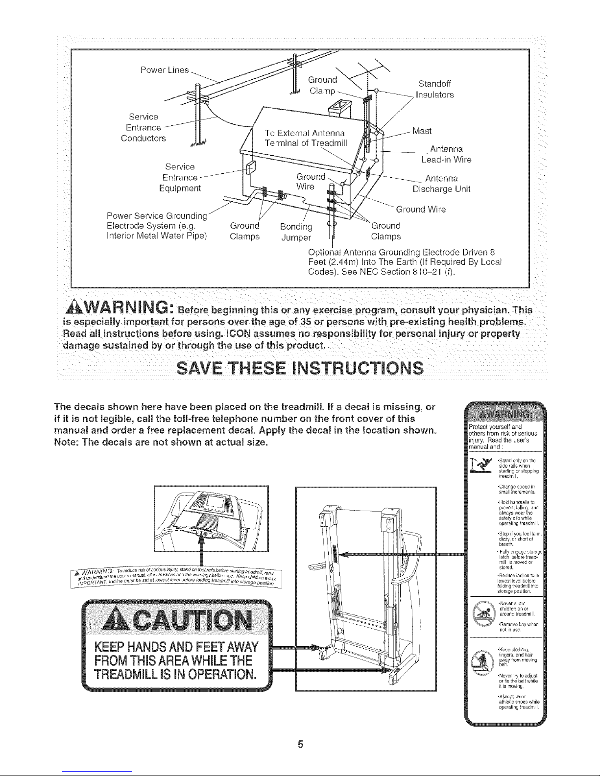
Power Lines
Service
Entrance..... "....
Conductors
Servlce
Entrance
Equipment
\
Ground Standoff
Ciamp --__ Insulators
To External Antenna
Termina _fTreadm
Ground. Antenna
Wire Discharge Unil
Antenna
Lead-in Wire
Power Service Groundingj
f
Electrode System e.g. Grounc/ Bonding
Interior Meta Water Pioel Clamos Jumper
Ground Wire
3round
Clamos
O otional Antenna Grounding Electrode Driven 8
Feet/2.44m} into The Earti if Reouired By Loca
Codes. See NEC Section 810-21 dL
,&WARNING: Beforebeg o.i.gth soraoVexere 0oprogram,coosultyo rphysician.Th s
is especially important for persons over the age of 35 or persons with pre=existing health problems.
Read aH instructions before using. _CON assumes no responsibility for personal injury or property
damage sustained by or through the use of this product.
SAVE THESE iNSTRUCTiONS
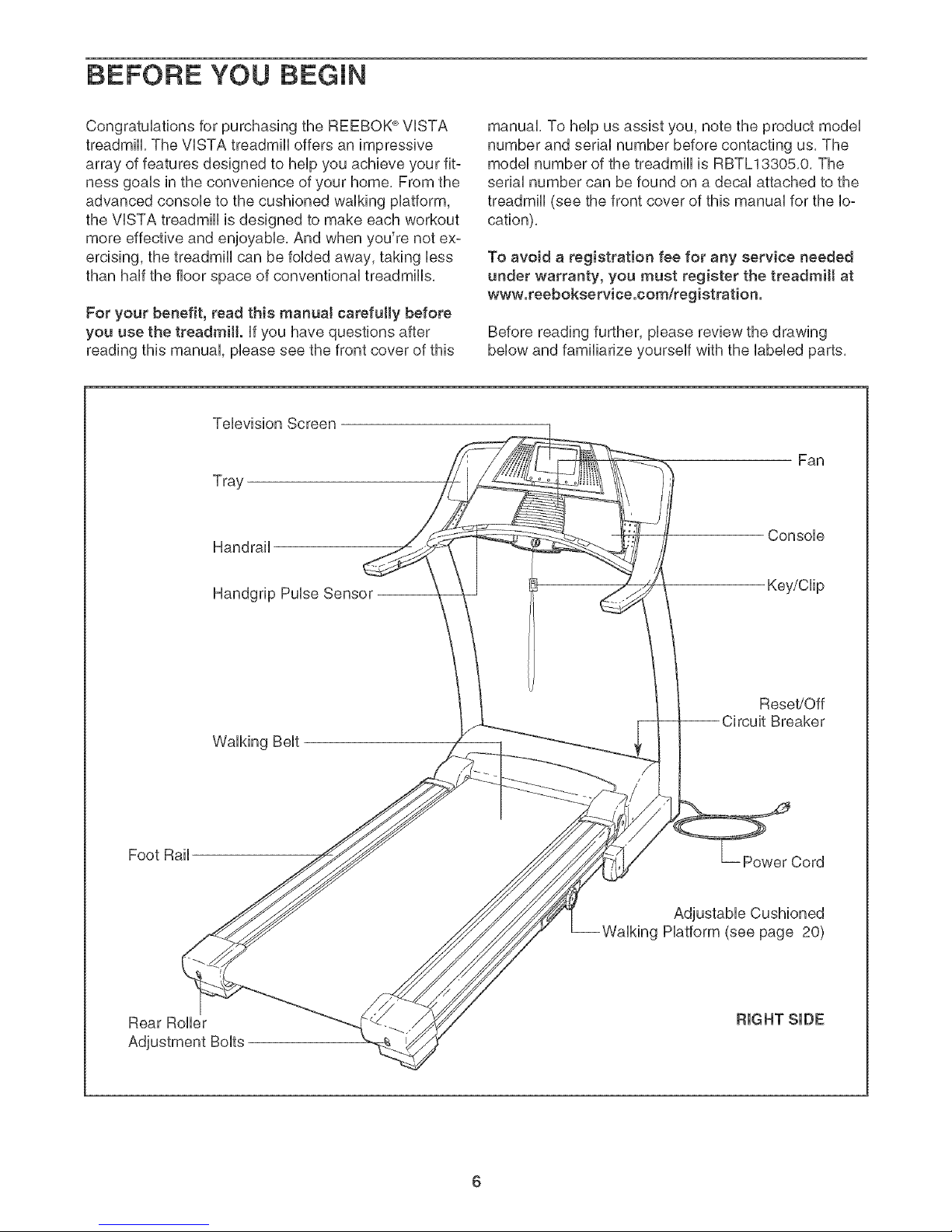
The decals shown here have been placed on the treadmill if a decal is missing, or
if it is not legibJe, caJ[ the toil-free telephone number on the front cover of this
manuaJ and order a free replacement decal Apply the decal in the tocation shown.
Note: The decaJs are not shown at actual size.
Protect yourself and
others from risk of serious
injury, Read the user's
manual and :
slde laJls wrlen
,Stand only on the
stading or stopping
treadmill.
•Change speed in
small increments.
,Hold handrails to
KEEPHANDSANDFEETAWAY
FROMTHISAREAWHILETHE
TREADMILLiS iN OPERATION.
operating treadmill.
.Slop if you feel faint,
dizzy, or short of
bleath.
• Fully engage storage
latch before tread-
mill is moved 0i
stored.
,Reduce incline to ils
lowest level before
folding treadmill into
storage position,
not in use,
,Keepclathing,
fingers, and hair
away frommoving
belt.
.Never lry to adiust
or fix the belt while
itis moving,
'Always wear
athlatic shoes while
operating treadmill.
5
BEFORE YOU BEGIN
Congratulations for purchasing the REEBOK ®VISTA
treadmill, The VISTA treadmill offers an impressive
array of features designed to help you achieve your fit-
ness goals in the convenience of your home, From the
advanced console to the cushioned walking platform,
the VISTA treadmill is designed to make each workout
more effective and enjoyable, And when you're not ex-
ercising, the treadmill can be folded away, taking less
than half the floor space of conventional treadmills,
For your benefit, read this manual carefully before
you use the treadmill, if you have questions after
reading this manual, please see the front cover of this
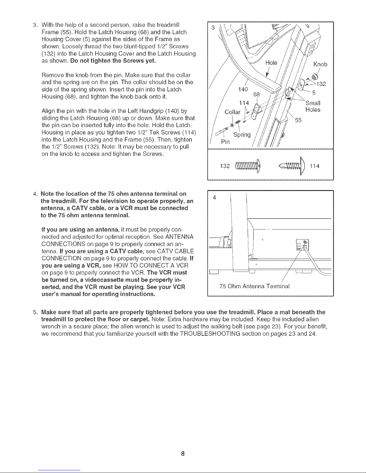
Television Screen
Tray
Handrail
manual, To help us assist you, note the product model
number and serial number before contacting us, The
model number of the treadmill is RBTL13305,0, The
serial number can be found on a decal attached to the
treadmill (see the front cover of this manual for the lo-
cation),
To avoid a registration fee for any service needed
under warranty, you must register the treadmill at
www.reebokservice.com/'registration.
Before reading further, please review the drawing
below and familiarize yourself with the labeled parts,
Fan
Console
Foot Rail
Rear Roller
Handgrip Pulse Sensor --
Walking Belt
Key/Clip
Reset/Off
Breaker
Power Cord
Adjustable Cushioned
Walking Platform (see page 20)
6

To hire an authorized service technician to assemble the treadmill, call toIFfree 1-800-445-2480. Assembly
requires two persons. Hace the treadmHUin a cbared area and remove aHpacking materiaUs, Do not
dispose of the packing materiab until the treadmHUis assembbd,
Note: The underside of the treadmHUwaUkingbeUtis coated with high@erformance Uubrbant, During shipping, a
small amount of Uubrbant may be transferred to the top of the waUking beUt,the sides of the walking platform, or
the shipping carton, This does not affect treadmill performance, If there is lubricant on top of the walking belt or
on the sides of the walking platform, wipe off the lubricant with a soft cloth and a mild, non-abrasive cleaner,
AssemMy requires a phillips screwdriver and the included allen wrench _. To avoid
damaging ptastic parts, do not use power toots for assembly.
With the help of a second person, carefully raise the
Uprights (65) to a vertical position,
Have the second person hold the console assembly near
the Uprights (65) as shown, Look under the console as°
sembly and locate the Console Wire Harness (71) and the
TV cable,
Cut the plastic ties securing the Upright Wire Harness
(85) and Upright TV Cable (100) to the Upright (65),
Connect the Upright TV Cable to the TV cable in the con-
sole assembly, Connect the Upright Wire Harness to the
Console Wire Harness (71), Make sure to connect the
connectors properJy (see the inset drawing}. The con-
nectors shouJd slide together easiJy and snap into
place. If the connectors do not slide together easily and
snap into place, turn one connector and try again, IF THE
CONNECTORS ARE NOT CONNECTED PROPERLY,
THE CONSOLE MAY BE DAMAGED WHEN THE
POWER IS TURNED ON.
insert the excess Wire Harnesses (71,85) and TV cable
into the Upright (65),
Set the console assembly on the Uprights (65), While a
second person holds the console assembly, attach the
console assembly with four 1" Console Bolts (138) and
four Console Washers (69) as shown, Firmly tighten the
Console Bolts,
1
Console Assembly
Console
i_71,85
133_
133
With the help of a second person, raise the treadmill
Frame (55), Hold the Latch Housing (68) and the Latch
Housing Cover (5) against the sides of the Frame as
shown, Loosely thread the two bluntqpped 1/2" Screws
(132) into the Latch Housing Cover and the Latch Housing
as shown, Do not tighten the Screws yet,
Remove the knob from the pin, Make sure that the collar
and the spring are on the pin, The collar should be on the
side of the spring shown, insert the pin into the Latch
Housing (68), and tighten the knob back onto it,
Align the pin with the hob in the Left Handgrip (140) by
sliding the Latch Housing (68) up or down, Make sure that
the pin can be inserted fully into the hob, Hold the Latch
Housing in place as you tighten two 1/2" Tek Screws (114)
into the Latch Housing and the Frame (55), Then, tighten
the 1/2" Screws (132), Note: it may be necessary to pull
on the knob to access and tighten the Screws,
Knob
32
Small
Hobs
Spring
Pin
132 _ _ 114
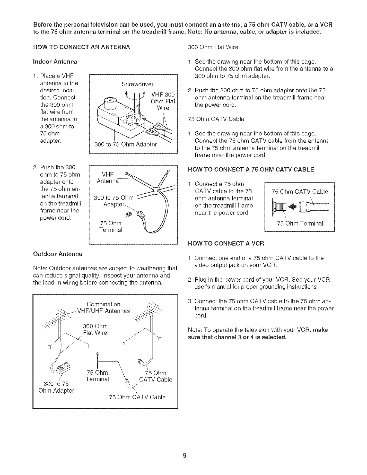
4, Note the tocation of the 75 ohm antenna terminaJ on
the treadmill. For the teJevision to operate properly, an
4
antenna, a CATV cable, or a VCR must be connected
to the 75 ohm antenna terminal.
if you are using an antenna, it must be properly con-
nected and adjusted for optimal reception, See ANTENNA
CONNECTIONS on page 9 to properly connect an an-
tenna, if you are using a CATV cable, see CATV CABLE
CONNECTION on page 9 to properly connect the cable, if
you are using a VCR, see HOW TO CONNECT A VCR
on page 9 to properly connect the VCR, The VCR must
_.j _L_
be turned on, a videocassette must be property in-
serted, and the VCR must be playing. See your VCR
75 Ohm Antenna Terminal
user's manual for operating instructions.
Make sure that aH parts are properly tightened before you use the treadmill. PJace a mat beneath the
treadmill to protect the floor or carpet. Note: Extra hardware may be induded, Keep the included allen
wrench in a secure place; the allen wrench is used to adjust the walking belt (see page 23), For your benefit,
we recommend that you familiarize yourself with the TROUBLESHOOTING section on pages 23 and 24,
Beforethepersonaltelevisioncanbeused,youmustconnectanantenna,a 75ohmCATVcable,or aVCR
tothe75ohmantennaterminalonthetreadmillframe.Note:Noantenna,cable,or adapteris included.
HOWTOCONNECTANANTENNA 300OhmFiatWire
Indoor Antenna
1. Place a VHF
antenna in the
desired loca-
tion. Connect
the 300 ohm
fiat wire from
the antenna to
a 300 ohm to
75 ohm
adapter.
2. Push the 300
ohm to 75 ohm
adapter onto
the 75 ohm an-
tenna terminal
on the treadmill
frame near the
power co rd.
Screwdriver
300 to 75 Ohm Adapter
VHF
Antenna
300 to 75 Ohm
Adapter.
75 Ohm
Terminal
VHF 300
Ohm Fiat
Wire
1. See the drawing near the bottom of this page.
Connect the 300 ohm fiat wire from the antenna to a
300 ohm to 75 ohm adapter.
2. Push the 300 ohm to 75 ohm adaptor onto the 75
ohm antenna terminal on the treadmill frame near
the power cord.
75 Ohm CATV Cabb
1,
See the drawing near the bottom of this page.
Connect the 75 ohm CATV cabb from the antenna
to the 75 ohm antenna terminal on the treadmill
frame near the power cord.
HOW TO CONNECT A 75 OHM CATV CABLE
1. Connect a 75 ohm
CATV cable to the 75
ohm antenna terminal
on the treadmill frame
near the power cord.
75 Ohm CATV Cable
75 Ohm Terminal
Outdoor Antenna
Note: Outdoor antennas are subject to weathering that
can reduce signal quality, inspect your antenna and
the bad-in wiring before connecting the antenna.
Combination
300 Ohm
Fiat Wire
75 Ohm
300 to 75
Ohm Adapter
75 Ohm CATV Cable
CATV CaNe
HOW TO CONNECT A VCR
1, Connect one end of a 75 ohm CATV cable to the
video output jack on your VCR,
2, Plug in the power cord of your VCR, See your VCR
user's manual for proper grounding instructions,
3. Connect the 75 ohm CATV cable to the 75 ohm an-
tenna terminal on the treadmill frame near the power
cord.
Note: To operate the television with your VCR, make
sure that channel 3 or 4 is selected.
 Loading...