

Reebok PURE, Pure Bike User Manual
PURE BIKE USER MANUAL

Welcome from Reebok Fitness.
Thank you for choosing this Reebok Pure Exercise Bike.
Before you get started, please read the instructions. Should
you experience any difficulties, our support team will be happy
to help or check out our website at:
Important note:
Consult your doctor before starting any exercise program.
If you feel any sickness, chest pain, fts of dizziness or
breathlessness during your training, stop exercising and
consult your doctor immediately.
Model name: Reebok Pure Bike
Serial number:
These details can be found on the underside of your product.
www.reebokftness.info
If you have any further queries please
customer support team on the number or email address on
the back of this manual.
call or email our

CONTENTS
Pre-assembly Notes
Assembly Steps
Computer Operation
Exloded Diagram
Parts List
Warm Up
Limited Warranty
11
13
15
16
08
01
Precautions
06
Maintenance
10
Assembly Diagram
12
02
PRE- ASSEMBLY NOTES
Open The Box
Make sure to inventory all of the parts that are included in the box.
Check the Hardware Chart for a full count of the number of parts
included for proper assembly. If you are missing any parts,
please call our Technical Support line
Gather Your Tools
Before starting the assembly of your unit, gather the necessary tools.
Having all of the tools at hand will save time and make the assembly
quick and hassle-free.
Clear Your Work Area
Make sure that you have cleared away a large enough space to properly
assemble the unit. Make sure the space is free from anything that many
cause injury during assembly. After the unit is fully assembled, make
sure there is a comfortable amount of free area around the unit for
unobstructed operation.
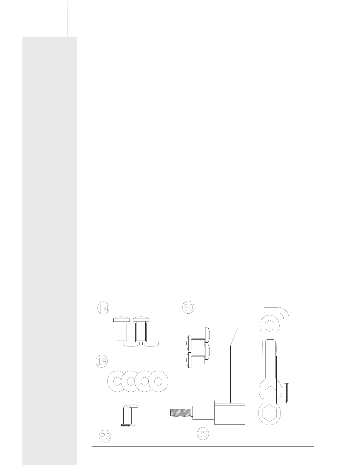
Hardware Chart
For your convenience, we have identified the hardware used in the
assembly of this product. This chart is provided to help you identify
those items that may be unfamiliar to you. If you find any parts missing
please contact our Technical Support line 0 .
0800 440 2459
800 440 2459
19.Arc Washer Φ8. 5*Φ22*T1.5
20.Allen Hard Bolt M8*15
23.ScrewΦ4*20
29.L Shape Knob
14.Allen Head Bolt M10*20
Spanner L15
Box Wrench
Allen key L6
4
4
4
2
1
1
1
1
Ø22*Ø8.5-4PCS
M10*20-4PCS
M8*15-4PCS
Ø4*20-2PCS
1 PC
TOOL:
L6-1pc,L13*17-1pc,L15-1pc
03
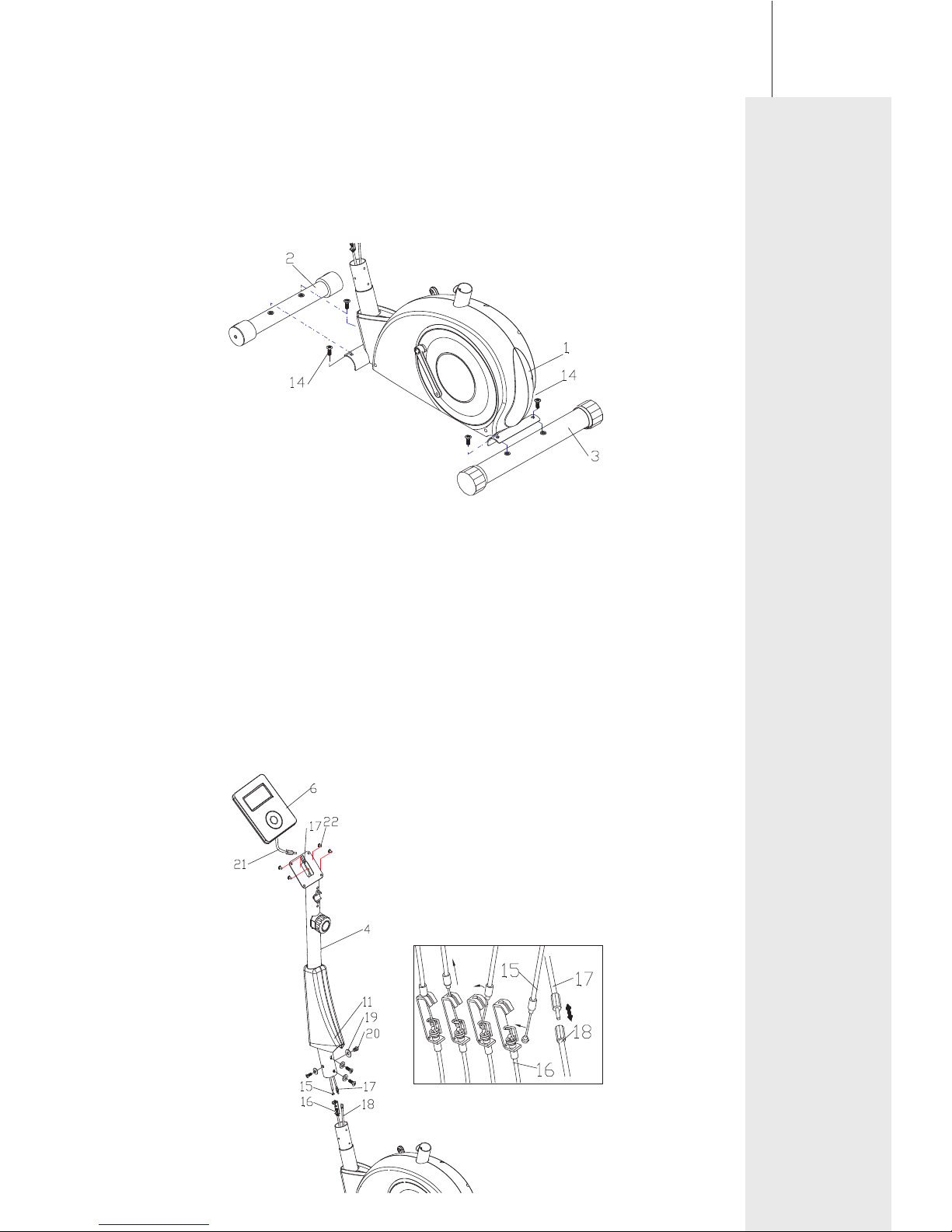
Step 1:
1-1: Attach Rear Stabilizer (3) to Main frame (1), fasten with Allen
Head Bolts (14), tighten with Allen Key.
1-2: Attach Front Stabilizer (2) to Main frame (1), fasten with Allen
Head Bolts (14), tighten with Allen Key.
ASSEMBLY STEPS
Step 2:
2-1:
2-2: Connect Middle Computer Wire (17) with Lower Computer Wire
(18).
2-3: Connect the Upper Tension Wire (15) with Lower Tension Wire
(16).
2-4: Insert Front Post (4) into Main frame (1), fasten with Allen Head
Bolt (20) and Arch Washers (19) tighen with Allen Key.
2-5: Connect the computer Wire(21) with the Middle computer wire(17).
Slide Front Post Cover (11) onto Front Post (4).( Lift it to the
position as the picture shown.)
Place the Front Post Cover (11) onto Main Frame (1).
Install Computer (6) onto Front Post (4) fasten by Screws (22) tightly
as shown.
04
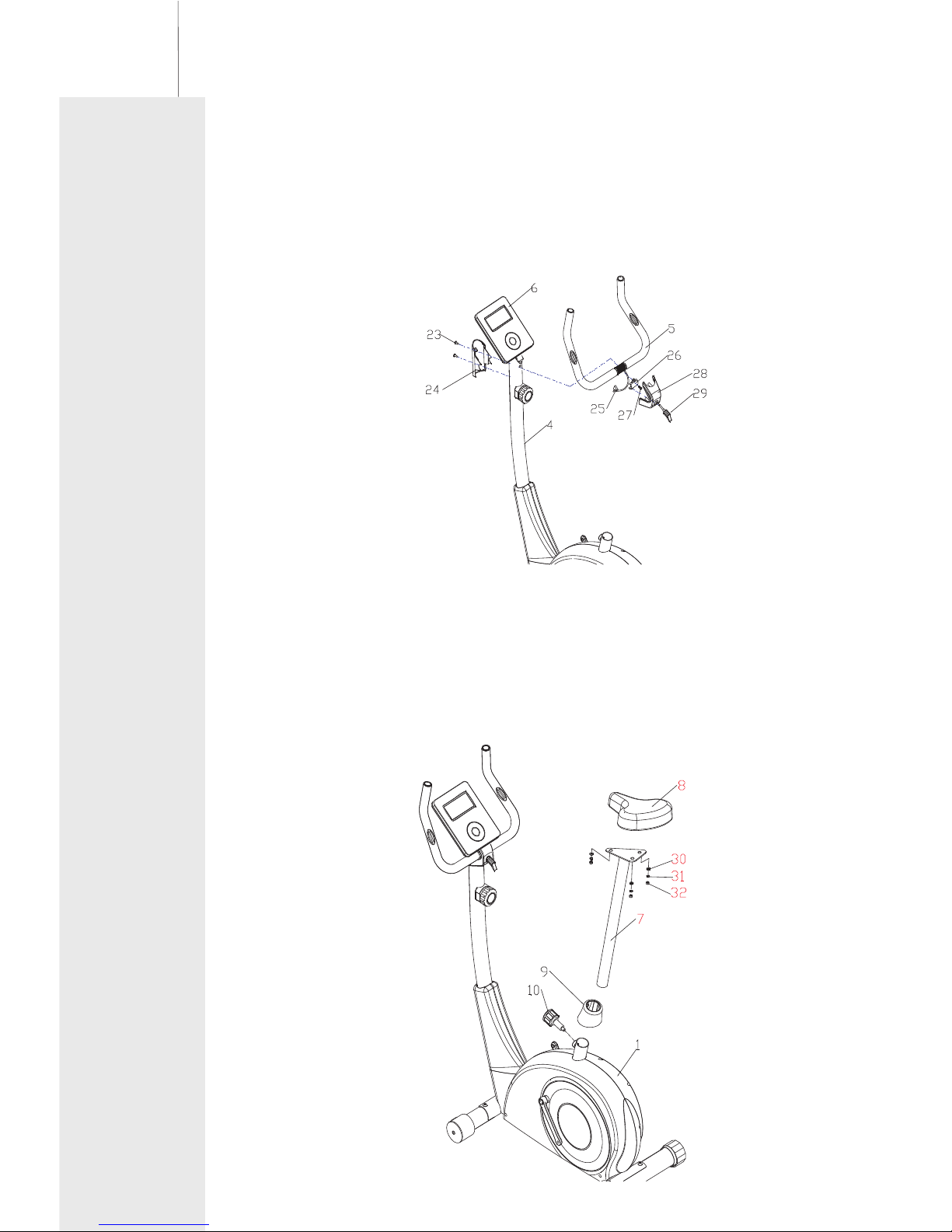
Step 3:
3-1: Secured Handlebar (5) onto Front Post (4), with Bracket (26),
fasten with Allen Head Bolt (27).
3-3: Plug the pulse sensor wire(25) to the back hold of the computer(6)
as shown below.
3-2:
with L shape Knob (29).Now fix Rear Bracket Cover (24) on the other side
and fasten with Screws(23).
Fix Front Bracket Cover (28) onto Handlebar (5), fasten to Handlebar (5)
Step 4:
4-1: Attach Seat (8) to Seat Post (7), fasten with Flat Washer (30),
Spring Washer (31), Nylon Nut (32).
4-2: the Quick Release Knob (10) from the Main Frame(1).
Place the Seat Post Cover (9) onto the Main Frame (1) as the
picture shown.
4-3: Insert Seat Post (7)into Main Frame(1), then line up the hole
and secure the seat in position with Quick Release Knob (10).
Remove
 Loading...