

Reebok i-Trainer.SE User Manual

reebokfitness.info
RFE International Ltd
The Performance Centre
Maidstone Road, Kingston
Milton Keynes MK10 0BD
+44 (0) 1908 793 020
info@rfeinternational.com
Customer Support
0800 440 2459
techsupport@rfeinternational.com
reebokfitness.info
i-Trainer.SE
Usermanual
RFE 4489_RE014201_iTrainerSE_UMFINAL.indd 1-1 25/06/2010 16:09

Reebok i-Trainer.SE
01
reebokfitness.info
Parts . . . . . . . . . . . . . . . . . . . . . . . . . . . . . . . . . . . . . . . . . . . . . . . . . . . . . . . . 02
Assembly. . . . . . . . . . . . . . . . . . . . . . . . . . . . . . . . . . . . . . . . . . . . . . . . . . . . 04
Precautions. . . . . . . . . . . . . . . . . . . . . . . . . . . . . . . . . . . . . . . . . . . . . . . . . . .14
Functions . . . . . . . . . . . . . . . . . . . . . . . . . . . . . . . . . . . . . . . . . . . . . . . . . . . . 16
Correct Use . . . . . . . . . . . . . . . . . . . . . . . . . . . . . . . . . . . . . . . . . . . . . . . . . . 17
Warm Up . . . . . . . . . . . . . . . . . . . . . . . . . . . . . . . . . . . . . . . . . . . . . . . . . . . . 18
Computer . . . . . . . . . . . . . . . . . . . . . . . . . . . . . . . . . . . . . . . . . . . . . . . . . . . .19
Maintenance . . . . . . . . . . . . . . . . . . . . . . . . . . . . . . . . . . . . . . . . . . . . . . . . 25
Troubleshooting . . . . . . . . . . . . . . . . . . . . . . . . . . . . . . . . . . . . . . . . . . . . . 26
Parts ID. . . . . . . . . . . . . . . . . . . . . . . . . . . . . . . . . . . . . . . . . . . . . . . . . . . . . . 28
Limited Warranty . . . . . . . . . . . . . . . . . . . . . . . . . . . . . . . . . . . . . . . . . . . . 32
Model name: Reebok i-Trainer.SE
Serial number: . . . . . . . . . . . . . . . . . . . . . . . . . . . . . . . . . . . . . . . . . . . . . . . . .
These details can be found on the underside of your product.
Thank you for choosing Reebok. Before you get
started, please read these instructions carefully.
If you experience any difficulties, our support
team will be happy to help – or check out our
website at reebokfitness.info
Welcome from
Reebok Fitness
Contents
Customer Support
0800 440 2459
techsupport@rfeinternational.com
Important note:
Consult your doctor before starting any exercise programme. If you feel any sickness, chest
pain, dizziness or breathlessness during your training, stop exercising and consult your
doctor immediately.
If you have any further queries please contact our customer support team on the details
provided either at the foot of this page or on the back of the manual.
RFE 4489_RE014201_iTrainerSE_UMFINAL.indd 1-1 25/06/2010 16:09
Reebok i-Trainer.SE
02
Customer Support 0800 440 2459 Reebok i-Trainer.SE
03
reebokfitness.info
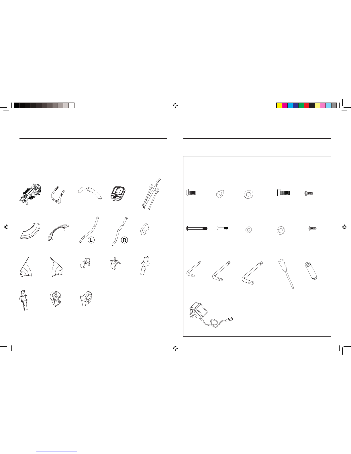
Checking The Parts
Before you begin, please check all parts are present and undamaged. If you are
missing any parts, please call our Technical Suppor t team on the number at the
top of this page.
117 x 1 238 x 1 842 x 1 288 x 1103 x 1
346 x 1 344 x 1 260 x 1213 x 1 340 x 1
804 x 1805 x 1 216 x 2 217 x 2
712 x 2 713 x 2
205 x 2
237 x 2
290 x 8
M8x12mm
219 x 2
M6x50mm
814 x 8
8mm
807 x 7
8mm
541 x 1
M5x29mm
220 x 2
6mm
373 x 5
8x17x1.5mm
215 x 5
M8x20mm
Parts
211 x 2
M4x10mm
802 x 12
M4x15mm
A x 1
4mm
F x 1
B x 1
5mm
C x 1
6mm
E x 1D x 1
Blister Pack
RFE 4489_RE014201_iTrainerSE_UMFINAL.indd 2-3 25/06/2010 16:09

Reebok i-Trainer.SE
04
Customer Support 0800 440 2459 Reebok i-Trainer.SE
05
reebokfitness.info
Assembly
Stabiliser
1. Remove the crosstrainer from the box.
2. Remove the transport stabiliser (fig.1). This is located at the back of the product
by loosening the 2 x 854 bolts . Retain the bolts for use in step 3.
3. There are three holes in the rear stabiliser (103). Attach the rear stabiliser to the
main frame, as shown, by fixing the 2 x 854 bolts and 2 x 807 spring washers
from the discarded transport stabiliser into the top two holes.
4. Now fix the rear stabiliser by inserting 1 x 215 bolt in the bottom hole, along with
1 x 807 spring washer and 1 x 373 flat washer.
1
854
807
215
373
103
807
Stabiliser continued
5. Once complete, clip the plastic cover (340) over the stabiliser.
You will require:
340 x 1
You will require:
807 x 3
215 x 1 373 x 1 103 x 1854 x 2
5mm
6mm
To aid access to the bolt holes during assembly, it may help to place the cross
trainer body on a piece of polystyrene packaging.
RFE 4489_RE014201_iTrainerSE_UMFINAL.indd 4-5 25/06/2010 16:09
340

Reebok i-Trainer.SE
06
Customer Support 0800 440 2459 Reebok i-Trainer.SE
07
reebokfitness.info
Assembly
3
2
1
Upright
6. Place the upright (288) through the upright cover (352) as shown (fig.1).
7. Connect the wires from the bottom of the upright to the main body of the
crosstrainer (fig.2).
You will hear a click, which will confirm those wires are connected together.
8. Fix the upright to the front of the cross trainer using 4 x 215 bolts, 4 x 807 spring
washers and 4 x 373 flat washers (fig.3).
Initially insert bolts to finger tight. Once the upright is correctly located tighten
each bolt properly using the Allen key.
215
807
373
288
352
2
1
Upright Covers
9. Push the upright cover (352) into place on the main body to cover the upright
bolts (fig.1).
10. Clip the handlebar cowlings (344 & 346) around the base of the upright (fig.2).
You will require:
344 x 1
346 x 1
344 346
807 x 4
You will require:
215 x 4 373 x 4
288 x 1 352 x 16mm
352
RFE 4489_RE014201_iTrainerSE_UMFINAL.indd 6-7 25/06/2010 16:09

Reebok i-Trainer.SE
08
Customer Support 0800 440 2459 Reebok i-Trainer.SE
09
reebokfitness.info
Assembly
Handles
11. Remove the nut, bolt and washers pre assembled into the front of the pedal arm (fig.1).
12. Connect the handle to the front of the pedal arm using these components,
as illustrated (fig.2).
13. Cover the end of the handlebar by fitting the handlebar cover inners (216 & 217) to the
handlebar cover outers (712 & 713) as shown and secure using 4 x 802 screws (fig.3).
14. Repeat this process for the other handlebar.
Front
Rear
1
2
3
217
713
802
Upper Handlebars and Covers
15. Push the tops of the upper handlebars (213 & 260) into the handlebar tubes (fig.1)
16. Fix these using 4 x 290 bolts and 4 x 814 curve washers into each handlebar.
17. Once both handlebars are secure, place the handlebar covers (205 & 237)
over the joint, and fix using 2 x 802 screws into each handlebar.
1
237
814
205
260 213
802
802
290
You will require:
802 x 8 712 x 2 216 x 2 217 x 2 713 x 2
6mm
712
216
802
You will require:
213 x 1
260 x 1
802 x 4
205 x 2 237 x 2814 x 8 290 x 8
5mm
RFE 4489_RE014201_iTrainerSE_UMFINAL.indd 8-9 25/06/2010 16:09
 Loading...