

16
GUARANTEE
Terms and Conditions for UK (outside UK contact your local distributor)
In the unlikely event of a product breakdown during the guarantee period you should
contact our Service and Repair Helpline who will be able to assist with the repair and
advise of the best course of action to be taken.
Please DO NOT remove the product prior to making this call as this may invalidate your
guarantee.
Service and Repair Tel: 0844 372 7766 or email: technical.services@redringxpelair.com
We guarantee this product for domestic use only, for a period of 24 months from the date of purchase.
Within the guarantee period we will resolve, free of charge, any manufacturing defects in the product
resulting from faulty workmanship or material on condition that:a) The product has been correctly installed and commissioned in accordance with our instructions and is
being used on the supply circuit or voltage printed on the rating plate.
b) The product has been used in accordance with these instructions and has not been tampered with
or otherwise subject to misuse, neglect or accident.
c) The product has not been taken apart, modified or repaired except by a person authorised by us.
d) Evidence of the date of purchase in the form of an invoice or receipt will be required in order to qualify
under the terms of this guarantee.
e) The guarantee period for products used in light commercial applications will be limited to 12 months.
We DO NOT recommend these products be used in heavy or unsupervised commercial applications.
f) For the service work to be undertaken free of charge, the work must only be undertaken by
Redring Xpelair Group Limited, or our approved agents.
g) Service under guarantee has no effect on the expiry date.
The guarantee on any exchanged parts or product ends when the original guarantee period ends.
EXCLUSIONS
This guarantee DOES NOT cover damage or defects arising from poor or incorrect installation, improper
use or lack of maintenance, including the build-up of limescale.
It is the responsibility of the installer to check that the installation parameters meet the requirements
of the products, and any relevant regulations.
If we are called out to a fault, which is subsequently identified as being an installation fault, we will make
a charge.
It is important that the routine checks are completed before calling us out, as many issues can be simply
diagnosed and resolved.
A charge will be made where a call under the terms of the guarantee has been booked and a failure was
not product related, or an engineer arrives and is not able to gain access.
We make no guarantees as to response time for repairs.
We will endeavour to achieve the most timely response possible but while we indicate an average
response time, this should not be taken as a guarantee.
The guarantee applies to a repair or replacement (at our discretion) of the product subject to the
conditions above, and DOES NOT cover compensation for the loss of the product or consequential
loss of any kind.
This guarantee does not apply to the repair or replacement of pressure relief devices, sprayheads, hoses,
accessories, isolating switches, electrical cable, fuses and/or circuit breakers.
This guarantee does not affect your statutory rights.
Full details of terms and conditions are available on request from: -
NEWCOMBE HOUSE, NEWCOMBE WAY, ORTON SOUTHGATE, PETERBOROUGH PE2 6SE
TEL: +44 (0) 1733 456789 / FAX: +44 (0) 1733 319610
Website: www.redring.co.uk
(A4 Leaflet No. 556-2056-01b)
IMPORTANT:
This booklet should be left with the user after
installation and demonstration.
Installation and User Guide
XPRESSIONS
and XPRESSIONS-PLUS
SMART ELECTRIC SHOWERS
2
THIS APPLIANCE CAN BE USED BY CHILDREN AGED FROM 8 YEARS AND
ABOVE AND PERSONS WITH REDUCED PHYSICAL, SENSORY OR MENTAL
CAPABILITIES, OR LACK OF EXPERIENCE AND KNOWLEDGE IF THEY HAVE
BEEN GIVEN SUPERVISION OR INSTRUCTION CONCERNING USE OF THE
APPLIANCE IN A SAFE WAY AND UNDERSTAND THE HAZARDS INVOLVED.
CHILDREN SHALL NOT PLAY WITH THE APPLIANCE.
CLEANING AND USER MAINTENANCE SHALL NOT BE MADE BY CHILDREN
· Your shower has been designed for
convenience, economy and safety of use,
provided that it is installed, used and
maintained in good working order and in
accordance with our instructions and
recommendations.
· ALL WIRING AND INSTALLATION
MUST BE SUPERVISED BY A
SUITABLY QUALIFIED PERSON.
· THIS APPLIANCE MUST BE
EARTHED.
· The installation must be in accordance with
the current edition of BS.7671 (the ‘IET Wiring
Regulations’) and ‘Part P’ of the ‘Building
Regulations’ in force at the time of installation.
Installations outside England and Wales must
also conform to any local regulations in effect
· This appliance is intended to be permanently
connected to the fixed electrical wiring of the
mains supply with its own dedicated supply.
· This appliance must NOT be fitted where it
may be subjected to freezing conditions.
· DO NOT switch the appliance on if you
suspect it of being frozen.
Wait until you are sure it has thawed out.
· This appliance is not suitable for mounting
into steam rooms or steam cubicles.
· Isolate the mains electrical and water supply
before removing the appliance front cover.
· DO NOT fit any sort of tap or control on the
appliance outlet.
The appliance is designed to have an open
outlet and should only be used with the
Manufacturer’s recommended fittings.
· THIS SHOWER IS DESIGNED AND
APPROVED TO EN-60335 WITH THE
HANDSET PROVIDED.
UNDER NO CIRCUMSTANCES MUST ANY
HANDSET THAT IS NOT APPROVED BY THE
MANUFACTURER BE USED WITH THIS
PRODUCT.
· Take care to avoid restricting the outlet of the
pressure relief device (fig.15).
If water is discharged from the pressure relief
device, maintenance will be required before
the appliance can be safely used.
· We DO NOT recommend this appliance be
used in heavy or unsupervised commercial
applications.
The following points will help you have a greater
understanding of how your shower works:
· The electric heating elements operate at a
constant rate, dependant on your chosen
power setting.
The required water temperature is achieved
by adjusting the rate of water flow.
The higher the water flow the lower the
temperature and vice versa.
The temperature of the water supplied from
the mains can vary considerably throughout
the year from 5 to 20°C.
This means that in the winter, flow rate will be
less than in the summer to achieve the same
outlet temperature.
In summer the ‘Economy’ (2 red bars) power
setting may give adequate hot water.
· Your shower is designed to stabilise
temperature changes caused by water
pressure fluctuations.
15
Xpressions Showers
Xpressions-Plus Showers
14
Please Note:-
The fitting of Spare Parts must be supervised
by a suitably qualified person.
Front Cover complete Cat No. 93672125
Heat Exchanger (7.2kW) Cat No. 93672122
Heat Exchanger (8.5kW) Cat No. 93672102
Heat Exchanger (9.5kW) Cat No. 93672103
Heat Exchanger Vessel Cat No. 93672114
Solenoid Valve Cat No. 93672126
Start stop switch Cat No. 93597891
Flow Valve Top Assembly Cat No. 93672105
Tank Clip Cat No. 93672106
Pressure Relief Device Cat No. 93672107
Heat Exchanger ‘O’-Rings Cat No. 93672108
Thermal Cut-Out Cat No. 93672109
Pressure Switch Assembly Cat No. 93672124
Detachable lower Section Cat No. 93672127
Terminal Block Set Cat No. 93672128
3-Mode Handset Cat No. 93590736
6-Mode Handset Cat No. 93590737
Chrome Shower Hose Cat No. 93672119
Height Adjuster Cat No. 93672132
Ø22mm Riser Rail Tube Cat No. 93672134
Ø22mm Riser Rail Brackets Cat No. 93672133
Additional accessories and spare parts
Please contact our After Sales Service
(see Section 5)
WRAS Water Isolating Valve Cat No. 93793757
Chrome Accessories Cat No. 83595318
Chrome Premium Accs Cat No. 83595319
Chrome Curved Accs Cat No. 83595320
Curtain and Rail Pack Cat No. 83792812
3
These can result from toilets being flushed or
taps being turned on and off.
When this happens your showering
temperature will be held within a controlled
band, provided that the minimum pressure
required by the shower is maintained (page.4)
If the water pressure falls below the minimum
pressure required, it is likely that the pressure
switch will turn off the power to the heating
elements, resulting in a cold shower.
· DO NOT place items such as soap, shampoo
or other such bottles on top of the unit.
Liquid could leak through the joint between
the cover and backplate, and possibly damage
the sealing rubber.
WARNING:
ALL WIRING AND INSTALLATION
MUST BE SUPERVISED BY A
SUITABLY QUALIFIED PERSON.
DO NOT INSTALL THIS SHOWER
WHERE IT MAY BE SUBJECTED TO
FREEZING CONDITIONS.
We recommend that the installation is done in
the following sequence.
a. Fixing the shower to the wall
b. Plumbing
c. Electrical connections
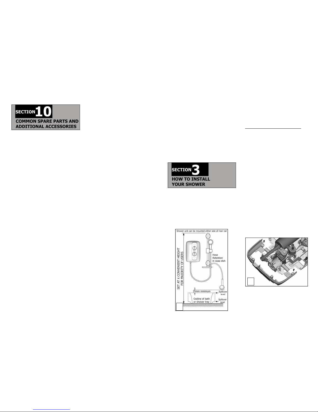
a. FIXING THE SHOWER TO THE WALL
1. Position the riser rail at a convenient height
for majority of users (fig.1) and mark its
position (see fig.9 for accessory details).
2. Position the heater so that the showerhead
cannot be immersed in the bath or shower
tray when hanging down.
Choose a flat piece of wall to avoid the
possibility of distorting the backplate thus
making the front cover a poor fit.
3. Adjust the position to get the most
convenient arrangement taking the following
into account.
· DO NOT MOUNT THE UNIT IN
THE DIRECT HANDSET SPRAY.
· The handset must not be able to come into
contact with used water in the cubicle, bath
or basin. If it can, even after the hose has
been retained by the soap-dish (fig.9),
a vacuum breaker must be fitted.
4. Fix the riser rail with screws provided (fig.9)
5. Remove the front cover by undoing the
retaining screws at the top and bottom of
the unit and lifting the cover off.
6. Remove the detachable lower section by
undoing the 2 x fixing screws (fig.2).
7. Decide the position of the electrical cable
into the unit. Your shower offers the ability
to have the connections on the right side or
the left. If left hand side is required the
terminal blocks will have to be moved from
the right to the left hand side (see fig.3).
2
1
 Loading...