

After Sales Service
We offer a technical advisory service on the telephone to installers and other customers with problems
in the field.
RING 0844 372 7766 (UK ONLY)
Remember to quote type of shower, as written on the front of the shower and on this leaflet.
The model and serial number are located on the bottom face of the shower.
Make a note of those numbers here, and be sure to quote them if you call for advice.
Model Number: 53--__________________ / Serial Number:____________________
Note: You may be charged for a service call if you do not have the serial number.
I
I
I
I
Full details of terms and conditions are available on request from:-
Redring Xpelair Group, Newcombe House,
Newcombe Way, Orton Southgate, Peterborough, PE2 6SE
Website: www.redring.co.uk
16
A3:567-2450-01 Rev B
We, Redring Xpelair Group Ltd., guarantee this product for domestic use only, for the period of 24
months from the date of purchase.
Within the guarantee period we will resolve, free of charge, any manufacturing defects in the product
resulting from faulty workmanship or material on the condition that:
I
I
I
A) The appliance has been correctly installed in accordance with our instructions and is being used on the supply
circuit or voltage printed on the rating plate.
B) The appliance has been used in accordance with these instructions and has not been tampered with or
otherwise subject to misuse, neglect or accident.
C) The appliance has not been taken apart, modified or repaired except by a person authorised by us.
D) Evidence of the date of purchase in the form of an invoice or receipt will be required in order to qualify for an
in-guarantee repair.
E) The guarantee period for the products used in commercial applications will be limited to 12 months.
F) For the service work to be undertaken free of charge, the work must be only undertaken by
Redring Xpelair Group Limited, or our approved agents.
G) Service under guarantee has no effect on the expiry date. The guarantee on any exchanged parts or product
ends when the original guarantee period ends.
EXCLUSIONS
This guarantee DOES NOT cover damage or defects arising from poor or incorrect installation, improper use or lack of maintenance,
including build-up of limescale. It is the responsibility of the installer to check that the installation parameters meet the requirements
of the product, and any relevant regulations.
If we are called out to a fault, which is subsequently identified as being an installation fault, we will make a charge. It is important
that the routine checks are completed before calling us out, as many issues can be simply diagnosed and resolved.
We make no guarantees as to response times for repairs. We will endeavour to achieve the most timely response possible but while
we indicate an average response time, this should not be taken as a guarantee.
The guarantee applies to a repair or replacement (at our discretion) of the product subject to the conditions above, and DOES NOT
cover compensation for the loss of the product or consequential loss of any kind
The guarantee does not apply to the repair or replacement of pressure relief devices, sprayheads, hoses, accessories, isolating
switches, electrical cable, fuses and/or circuit breakers.
This guarantee does not affect your statutory rights.
I
I
I
I
I
I
I
I
I
I
I
GUARANTEE
Terms and Conditions for UK (outside UK contact your local distributor)
IMPORTANT
This booklet should be given to the customer after installation and demonstration
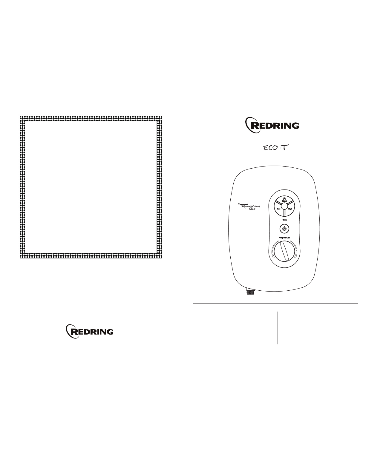
Thermostatic Instantaneous Electronic Shower
Handbook
Xpressions
User
Information
How To Start Your Shower
How To Operate Your Shower
How your shower works
Handset Operation
Routine Maintenance
Periodical Maintenance
Trouble Shooting (User)
Guarantee
Contents
Installer
Information
Installation Instructions
Plumbing Connections
Electrical Connections
Commissioning
Trouble Shooting (Installer)
Spares
Page
Page
2
3
5
7
14
15
8
9
10
12
12
13
13/14
16
A TYPICAL INSTANTANEOUS ELECTRIC SHOWER INSTALLATION
Mains cold water supply
(either top, bottom
or rear entry)
Height of spray head
and shower to suit
user’s requirements
2
Installation Instructions
ALL WIRING AND INSTALLATION MUST BE
SUPERVISED BY A SUITABLY QUALIFIED
PERSON.
We recommend that the installation be done in
the following sequence: -
a) Fix the shower to the wall
b) Plumbing
c) Electrical connections
d) Commissioning
Warning! Do Not Install The Shower In A
Room Where It May Be Subject To Freezing
a) Fix The Shower To The Wall
When deciding where to place the unit a few
things need to be taken into consideration: -
1) The unit MUST NOT be mounted directly
in the path of the spray from the handset
2) The handset could be used over a sink for
hair washing.
3) The handset does not come into contact
with the used water in the cubicle, bath or
basin.
A hose retainer is supplied with the
Accessories (See Diagram 22).
4) The unit can be mounted at a lower level for
less able users combined with optional
extended hose and riser rail.
The installation must comply with BS 8300:
2001.(Design of buildings and their
approaches to meet the needs of disabled
people. Code of practice).Remembering to
Adhere to point 1.
5) Choose a flat piece of wall to avoid the
possibility of distorting the backplate and
making the front cover a poor fit.
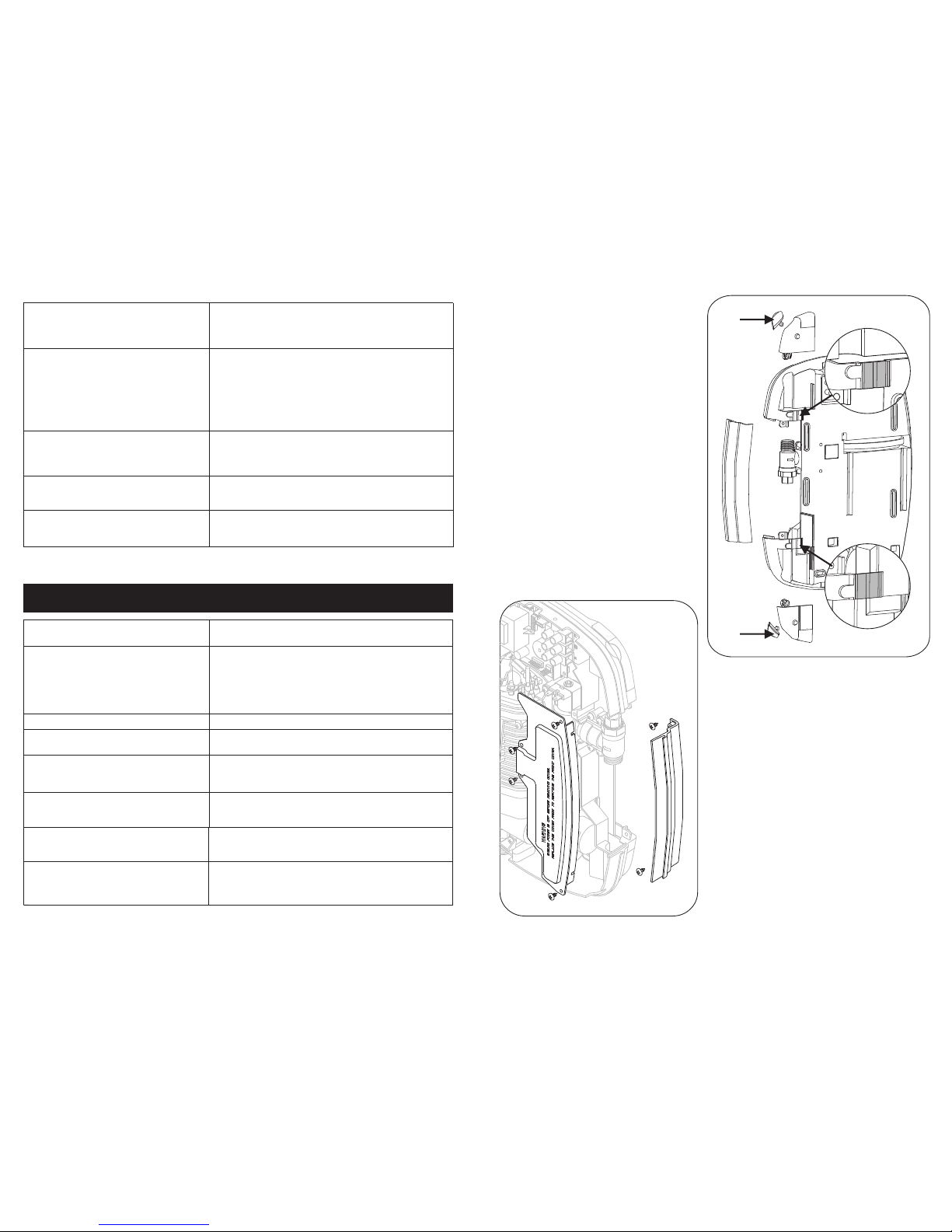
Remove the four cover screws and lift the cover
off.
Remove the four inlet cover screws and remove
inlet cover - also the two side access trimplate
section screws and remove complete with seal.
Hold the shower vertically against the wall and
mark the top hole first.
Having determined the direction of the inlet
water mains supply and cable approach for the
installation (Top, Bottom, or Rear or any
combination) - it is necessary to remove the
appropriate section inserts. See Plumbing
Connections and Electrical Installation
sections (Pages 3 and 5) for detailed guidance.
Drill the hole to take the rawl plug provided (taking
care to keep dust away from the shower).
Put the top screw in first leaving it proud by 5mm
approximately. The shower can now be hung on this
screw.
Position the shower so that it is vertical then mark
and drill the other two holes. Then fix the Shower to
the wall.
Assemble the accessories as shown in Diagram 22.
Remove the four cover screws and lift the
cover off.
Spares (Ring 0844 372 7750 UK ONLY)
Description
Triac PCB
Flow Valve Assembly (no PCB)
Flow Transducer
Heat Exchanger 7.2kW
Heat Exchanger 8.5kW
Heat exchanger 9.5kW
Thermal Cut-Out c/w Cables
Cable/Pipe Entry Set
PRV Housing Complete
Front Cover Complete white
Front Cover Complete Black
Front Cover Complete SIlver
Front Cover Complete Atlas Chrome
Part No,
93594158
93594159
93594160
93594161
93594162
93594163
93594117
93594164
93594165
93594166
93594139
93594141
93594142
Description
Backplate Rubber Seal Set
Solenoid Valve c/w Seals
6-Mode Handset White/Grey
1.25m Long Chrome Shower Hose
Wall Bracket Set
22mm x 455mm Bright Riser Rail
Height Adjuster Assy
Main Logic Board
Valve Rotation sensor PCB + wheel
Inlet Thermistor
Inlet Filter Housing Complete
Backplate Trimplate
Backplate Side Section
Part No.
93594150
93594154
93550895
93550896
93593522
93593526
93550899
93594167
93594168
93594169
93594144
93594145
93594146
Diagram 22
Please Note:- The fitting of all spares should be supervised by a suitably qualified person
15
264 mm
364 mm
680 mm
207 mm
Product Dimensions
Plumbing Connections
Plumbing to be carried out before wiring
DO NOT use jointing compounds on any pipe
fittings for the installation.
DO NOT solder fittings near the shower unit
as heat can travel along pipework and
damage components.
Compression fittings MUST be used to
connect to the inlet of the shower.
Note: We recommended that a WRAS (Water
Regulations Advisory Scheme) listed isolating
valve be fitted between the rising main and
the unit. This will allow the unit to be serviced
without having to turn off the house water at
the stop valve.
The unit should be connected to the mains
COLD water supply. This must have a
minimum running pressure of 0.07 MPa
(0.7bar / 10 p.s.i.) and a maximum pressure
of 1MPa (10bar / 145 p.s.i.).
This unit can also be fed from a header tank
provided this has a minimum head of 7 metres
(23ft).
IMPORTANT: Before completing the
connection of the water supply to the inlet of the
shower, flush out the pipework to remove all
swarf and system debris. This can be achieved
by connecting a hose to the pipework and
turning on the mains water supply long enough
to clear the debris to waste.
A blockage in the waterways (particularly the spray
plate of the handset and solenoid valve) will prevent
the unit from working correctly.
The shower is designed to have an open outlet and
should ONLY be used with the fittings recommended
by the manufacture.
Installation Procedure
Turn off the water supply either at the mains
stopvalve or the isolating stopvalve.
For ease of access to the inlet fitting the right hand
side of the shower has a removable inlet cover. See
Diagram 1. Also remove the backplate side access
trimplate shown in Diagram 1.
Diagram 2
A
B
C
D
Diagram 1
3
d) Lights behaves erratically.
e) Water does not flow when START/STOP
buttons are pressed.
Lights ON.
No lights.
I
I
I
I
I
I
I
Switch OFF electricity at ceiling/wall isolating switch,
wait a few seconds, switch on again.
(Note: The shower should be switched OFF each
time after use at the ceiling/wall isolating switch.
Note: If there is no water flowing then the shower will
automatically switch OFF after about 5 seconds.
Check the water supply is turned ON.
Check ceiling/wall isolating switch is ON.
Check power is ON.
I
I
I
I
I
I
PROFESSIONAL SERVICE CHECK LIST
This additional checklist is provided for the benefit of the qualified service representative.
WARNING! Switch Off The Electricity At The Isolator Before Removing The Front Cover To
Make Checks.
a) Poor temperature control.
b) Water too COLD
c) Poor or no control over water flow.
d) No water when button are pressed.
e) Unit has been switched OFF using
START/STOP button but can be heard
heating the water.
f) Pressure relief valve operated.
I
I
I
I
I
Check inlet thermistor to see if it is in circuit.
Check for blockage in the inlet filter.
Check circuit through thermal cut-out.
Check circuit through all 3 elements.
Test should be done using a low voltage resistance
meter whilst the power is switched OFF at the isolating
switch.
Check working voltage.
Replace flow valve assembly.
Check water supply. Check circuit through solenoid coil.
If OK replace logic PCB.
Replace triac PCB.
Check for cause of high pressure and remove it.
Replace pressure relief valve. (Not covered under
Guarantee).
I
I
I
I
I
g) Shower has a limited temperature
adjustment range.
h) Shower runs for about 5 seconds and
then switches OFF by itself.
I
I
Unit has been set with Temperature limiter set at 43°C.
Flow transducer fault.
Check that internal blade “spins” when the water flows:
If not, replace transducer.
I
I
14
f) Shower runs on about 5 seconds after
pressing Start / Stop Button then
switches OFF.
This is normal. Unit is in phased shutdown mode
indicated by the relevant LED flashing.
Re-press the High (or Eco) button and re-adjust the
temperature dial to give the desired temperature.
Re-press the High (or Eco) button and re-adjust the
temperature dial to give the desired temperature.
g) The flow rate is too low but the
temperature is correct.
h) The temperature dial is at its hottest but
the temperature is too low.
 Loading...