

8
Full details of terms and conditions are available on request from: -
APPLIED ENERGY PRODUCTS LIMITED,
MORLEY WAY, PETERBOROUGH PE2 9JJ
TEL +44 (0) 844 372 7750 / FAX: +44 (0) 844 372 7760
Website: www.applied-energy.com
(A4 Leaflet No. 578-2018-12a)
Point of Use Water Heater
Installation & Instruction Manual
THIS APPLIANCE IS NOT INTENDED FOR USE BY PERSONS
(INCLUDING CHILDREN) WITH REDUCED PHYSICAL, SENSORY OR MENTAL
CAPABILITIES, OR LACK OF EXPERIENCE AND KNOWLEDGE, UNLESS THEY
HAVE BEEN GIVEN SUPERVISION OR INSTRUCTION CONCERNING USE
OF THE APPLIANCE BY A PERSON RESPONSIBLE FOR THEIR SAFETY.
CHILDREN SHOULD BE SUPERVISED TO ENSURE THAT THEY
DO NOT PLAY WITH THE APPLIANCE.
These instructions should be read in full before commencing the installation.
We recommend that the installation should only be carried out by a suitably qualified
person.
The Redring WS7-EcoT heater is an open outlet, thermal storage water heater for use
with Redring recommended fittings for one outlet only.
It operates on the displacement principle i.e. when cold water is admitted into the
bottom of the tank, hot water flows out through the outlet.
Installation
We recommend that this unit should be installed in the following order:
1. Fit wall bracket.
2. Fit mains electrical cable to the unit.
3. Fit heater to the wall.
4. Connect plumbing to the unit.
5. Replace the front cover.
6. Fill the unit with water and check for leaks.
7. Connect mains electrical cable to the fixed wiring.
8. Set the weekly mechanical timer.
9. Turn unit on and check operation.
10. Demonstrate operation to user.
Please Note:When removing the front cover, we recommend that you first remove the two top fixing
screws, but only LOOSEN the two bottom screws.
This will aid when replacing the front cover during installation.
2
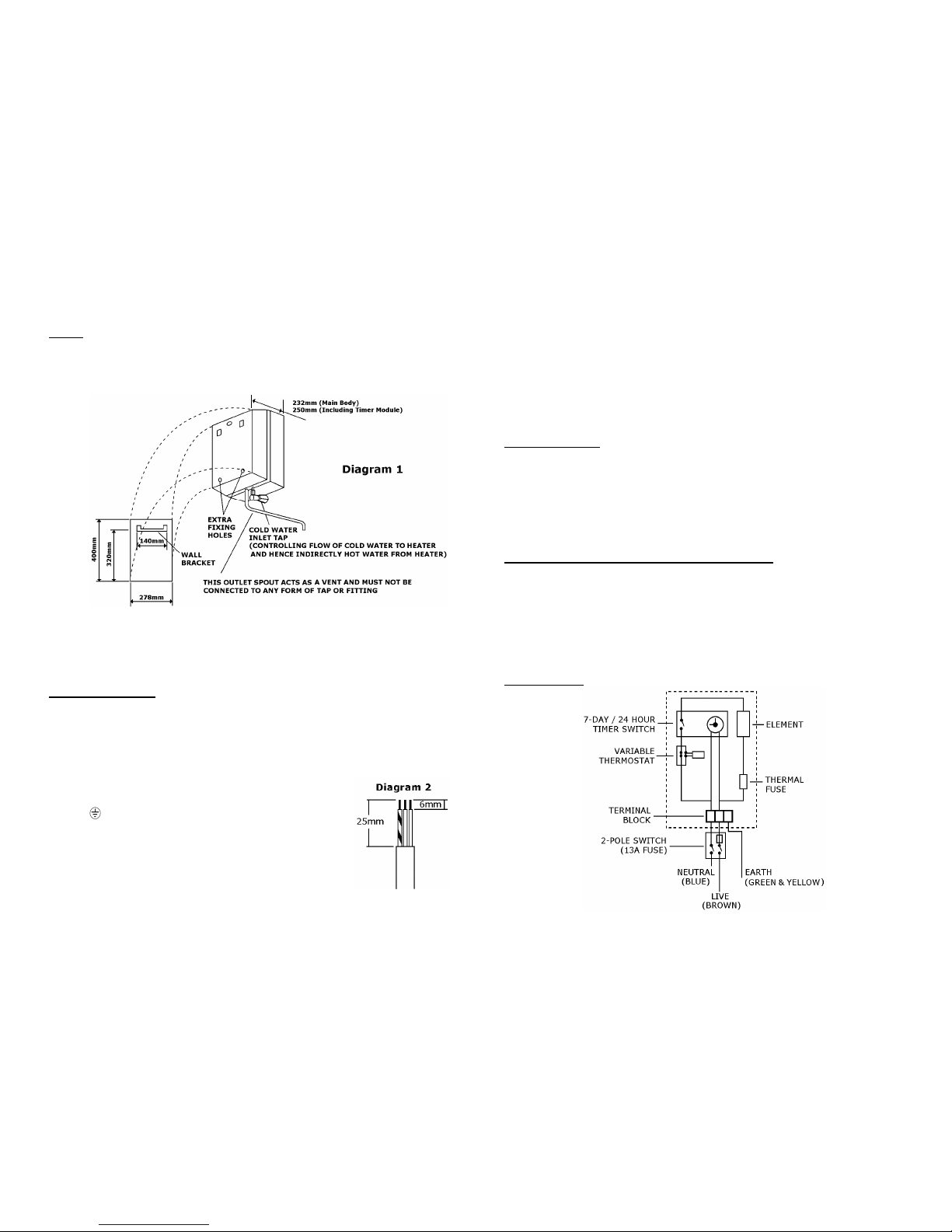
Fixing (see Diagram 1)
The wall bracket should be securely fixed in position.
The heater is then hung on the wall bracket.
Further security can be obtained by marking the position of the extra fixing holes as
shown and applying appropriate wall fixings to these positions.
When the unit is used above the sink with the cold inlet tap and spout supplied, it is
recommended that these extra fixing positions be used.
The bottom of the heater should be approximately 350mm above the top of the sink.
The outlet should be at least 13mm above the maximum possible water
level for any unit that is to be filled from the heater.
Electrical Connection
The installation must be in accordance with the current BS7671 - IEE Wiring Regulations
and “Part P” of the Building Regulations.
WARNING: THE UNIT MUST BE FILLED WITH WATER
BEFORE POWER IS SWITCHED ON.
1. The heater is suitable for 240/230V single phase A.C supply.
2. The live (brown) and neutral (blue) wires must be connected
to the designated positions in the terminal block and the
earth (green/yellow) to the earth position.
3. WARNING: THIS UNIT MUST BE EARTHED
4. The mains cable should be prepared as shown (see Diagram 2)
5. A means for disconnection in all poles must be incorporated in
the fixed wiring in accordance with the wiring rules.
6. The cable should be heat resisting 3-core flexible PVC of 1.25mm² minimum.
7
Installation Engineer Note:
The most likely reason for no heated water is an open circuit thermal fuse.
See label on front insulation for details.
This can be caused at initial commissioning if the heating element is energized with no
water in the tank.
Alternatively, it may be due to a back siphonage in the cold water supply caused by a
break or disconnection.
If you feel that your installation may suffer from a water failure, we recommend the
fitting of a non-return water check valve.
After Sales Service
We offer a technical advisory service on the telephone to contractors and other
customers with problems in the field.
Ring: 0844 372 7766
Fax: 0844 372 7767
Remember to quote the exact type of unit, as written on the front of this leaflet.
It may also be of use to have a note of the model and serial number as stated on the
underside of the unit.
Common Spare Parts and Recommended Accessories
The fitting of Spare Parts must be supervised by a suitably qualified person.
Common Spare Parts Recommended Accessories
Thermal Fuse Cat No. 94-780456 Swivel Arm (450mm) Cat No. 84-780404
7-Day Timer Cat No. 94-780457 Swivel Arm (600mm) Cat No. 84-780405
Front Cover Assy Cat No. 94-780458 Monoblock Mixer Tap Cat No. 84-780408
Common Spare Parts and Recommended Accessories can be supplied from
Redring Sales Hotline (RING) 0844 372 7766 or (FAX) 0844 372 7767
Circuit Diagram
 Loading...