

Redring PURE 8.5kW, PURE 7.5kW, PURE 9.5kW, PURE 10.5kW, Vital RVLS7 Installation And User Manual
...
IMPORTANT:
This booklet should be left with the user after
installation and demonstration
7.5/8.5/9.5/10.5kW
PURE
Installation and User Guide

2
1 – Pack Contents 3
2 – Installation Check List 3
3 – Important Safety Information 4
4 – General Installation Layout Guide 5
5 – Important Installation Information 6
6 – Fixing the Shower to the Wall 6
7 – Product Positioning Guide 7
8 – Plumbing Connections 8
9 – Electrical Connections 9-10
10 – Fitting the Front Cover 10
11 – Riser Rail Fitting Instructions 11
12 – Commissioning the Shower 12
13 – Troubleshooting Checklist for the Installer 13
1 – Important Safety Information 14
2 – Operating the Shower 15
3 – How Your Shower Works 16
4 – Routine Maintenance 16
5 – Troubleshooting and FAQs 17
6 – Troubleshooting Checklist for the Installer 18
7 – Energy Related Product Directive (ErP) 19
User Guide
Installation Guide
Contents
Installation Guide
IMPORTANT: This appliance can be used by children aged from 3
years and above and persons with reduced physical, sensory or
mental capabilities or lack of experience and knowledge if they
have been given supervision or instruction concerning use of the
appliance in a safe way and understand the hazards involved.
The shower spray head MUST be cleaned regularly to remove
scale and debris. The frequency of the cleaning will vary according
to the local water quality. If the water outlet temperature becomes
hot and you are unable to obtain cooler water, immediately check
the shower handset for blockage. See section 4 for cleaning
instructions.
Do not operate shower if frozen, or suspected of being frozen. It
must thaw out before using.

3
Installation Guide
Shower Unit
Shower Handset
Riser Rail Tube
Riser Rail Brackets x 2
Riser Rail Height Adjuster
Flexible Shower Hose
Screw Pack
Installation and User Instructions
Please make sure ALL components are included before starting the installation.
1. Pack Contents
2. Installation Check List
Check that the water supply will satisfy requirements
Check that water & cable entry points of the unit meet requirements
Check that the electric supply will satisfy requirements
Select a suitable position for the shower
Follow plumbing installation section
Follow electrical installation section
Fit to the wall & connect the shower supplies
Commission the shower in the way described
Fit the front cover & aligning the controls
Familiarise yourself with the user operating instructions
4
Installation Guide
Products manufactured by Redring Xpelair Group are safe and without risk
provided they are installed, used and maintained in good working order in
accordance with our instructions and recommendations.
3. Important Safety Information
MAINS SERVICE CONNECTIONS: The shower unit is supplied
for right hand entry, please see Section 8 & 9 for “Plumbing
Connections” & "Electrical Connections" for installation information.
IMPORTANT: To comply with water regulations, building
regulations or any specic local water company regulations and in
accordance with BS EN 806 a double check valve should be tted
where it is possible that the shower head may come into contact
with used water, for example in the bath or a shower tray.
IMPORTANT: Check that there are no hidden cables or pipes
before drilling holes for the wall plugs. Choose a at piece of wall
to avoid the possibility of distorting the back plate and making
the front cover a poor t. Exercise great care when using power
tools near water. The use of a residual current device (RCD) is
recommended.
IMPORTANT: Before connecting the water supply to the shower
unit the water supply pipe should be ushed out to remove all
debris. After ushing the pipework make the connection to shower
inlet and ensure the shower is positioned squarely on the wall and
all xing screws are tightened.
IT IS VERY IMPORTANT: To ensure that the terminal block
screws are fully tightened and that no cable insulation is trapped
under screws, and tighten periodically in accordance with BS
7671. The earth continuity conductor of the electrical installation
must be effectively connected to all exposed metal parts of other
appliances and services in the room in which the shower unit is
installed to conform with BS 7671. The unused supply terminal
block must not be used for any other purpose.
IMPORTANT: Ensure that the temperature control knob is
turned to MIN temperature (FULL ow) and the commissioning
instructions are followed before switching the unit on. This will
make sure that the unit is full of water when rst activated.
IMPORTANT: The shower unit MUST be full of water before the
heat settings are changed.
IMPORTANT: The shower unit MUST be tted with a WRAS
(Water Regulations Advice Scheme) listed mains water isolating
valve.
5
Installation Guide
• For example the mains feed to a toilet as
this may cause a drop in pressure to a level
that is too low for the shower unit to work
correctly.
• A WRAS (Water Regulations Advice
Scheme) listed isolating valve must be
tted between the rising main and the
unit to comply with water regulations and
to allow for routine maintenance and
servicing.
• Plan your installation carefully. Check on
the nearest and most accessible rising
main water supply, this may be beneath
the bath or in the loft, where it feeds the
water storage tank. Use only the cold rising
water main.
• If possible avoid connecting the shower
unit where it will be affected by water
drawn off by another appliance.
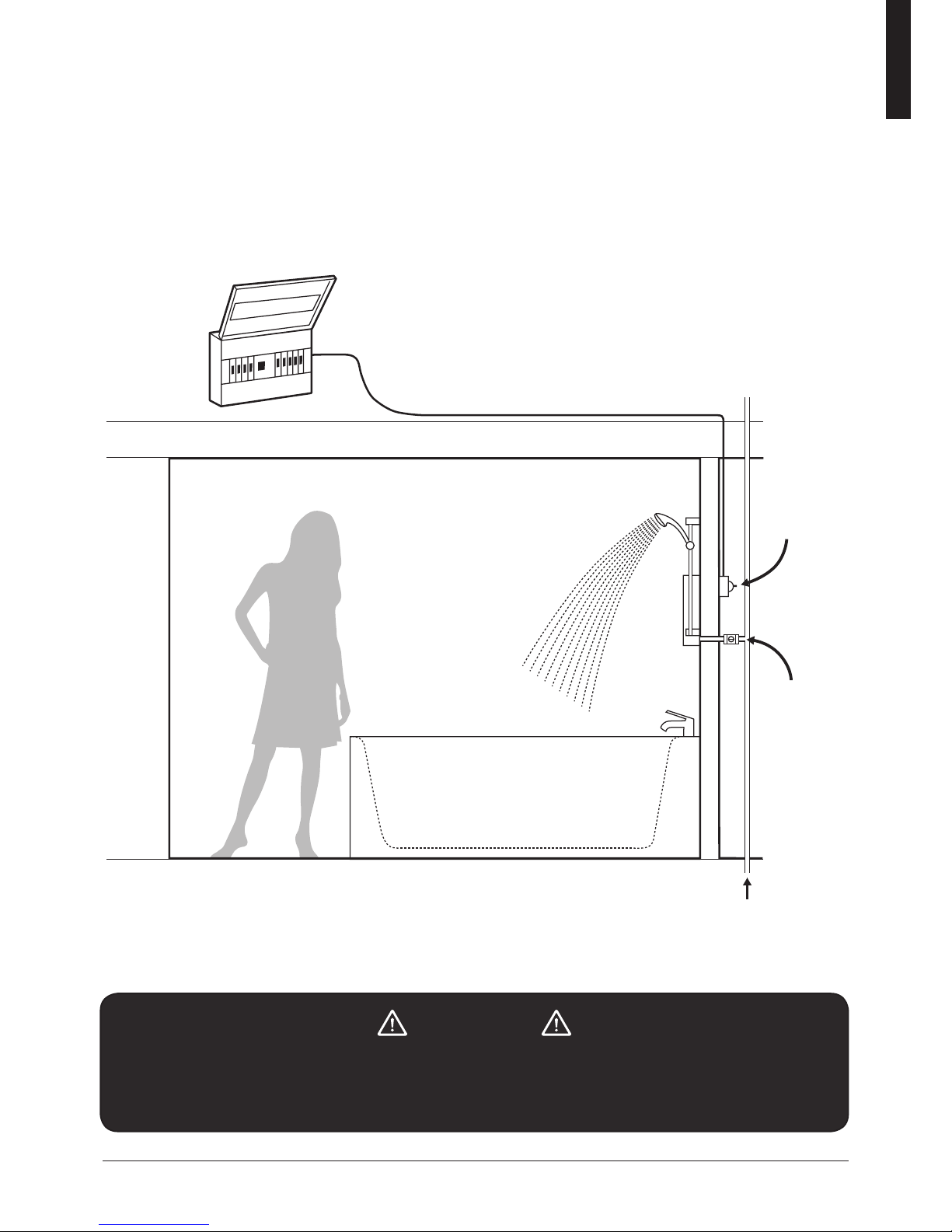
ELECTRICAL
ISOLATION
SWITCH IN
ACCORDANCE
WITH I.E.T BS
7671
MAINS WATER
ISOLATING
TAP
COLD WATER
MAINS SUPPLY
SEPARATE PERMANENTLY
CONNECTED CONSUMER UNIT
FLOOR
BATH
BATHROOM
CEILING JOISTS
4. General Installation Layout Guide
IMPORTANT!
This appliance can be used by children aged from 3 years and above and persons with
reduced physical, sensory or mental capabilities or lack of experience and knowledge
if they have been given supervision or instruction concerning use of the appliance in a
safe way and understand the hazards involved.
6
Installation Guide
• This shower unit is designed to be
connected to a 15mm cold water mains
supply.
• To make sure the heating elements are
activated the shower must be connected
to mains water supply with a minimum
static pressure of 0.1MPa (15lb/sq in) – 1
bar at a minimum ow rate of 8 litres per
minute. The maximum static pressure is
1MPa (145lb/sq in) 10 bar.
• The shower unit must not be tted where it
may be exposed to frost, for example, in an
outdoor area. The shower must not be used
if suspected of being frozen. Frost damage
is not covered by the guarantee.
NOTE: For the 9.5 & 10.5kW model, the
minimum running pressure must be obtained
at 9 L/min.
• Position your shower on a FLAT section of wall,
ensuring that it will NOT be in the direct water spray
from the shower handset when xed.
• The shower unit should be positioned so that the
shower handset cannot be immersed in the bath or
shower tray when hanging down.
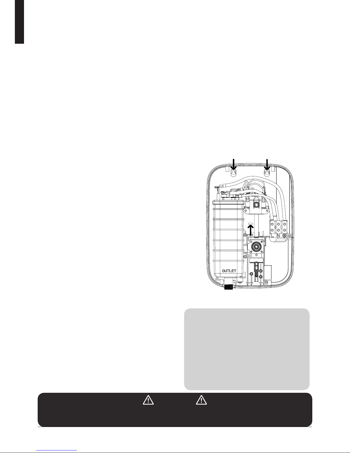
• Remove the four front cover xing screws and lift the
cover off complete with the control knobs and start /
stop push button.
1. Having decided on the water and cable entry
points and chosen a at piece of wall, hold the
shower vertically against the wall and mark the
top two xing holes whilst ensuring the shower
is square.
2. Carefully drill the two holes as marked using
a sharp 5.5mm masonry drill after rst making
certain there are no pipes or wires behind the
proposed holes.
3. Insert the wall plugs and screws provided
leaving the screw head proud by approximately
5mm. The shower can now be hung on these
screws.
4. Make sure that the shower is positioned
vertically and square, now mark and drill the
lower slotted xing hole. Then x the shower to
the wall. Do not fully tighten the screws at this
stage
5. The shower back plate and removable corn er
mouldings have moulded cut out sections which
are clearly indicated to allow the chosen service
entry option to be cut out prior to nal x.
Shower installation must be carried out by a suitably qualied person and be in
accordance with BS 7671 (IET wiring regulations), building regulations, water regulations
and / or any specic local water company regulations in force and should be in
accordance with BS EN 806.
• Plumbers jointing compound must not
be used. In instances of difcult joints
use P.T.F.E. Tape. The use of jointing
compound will invalidate the product
guarantee.
• Do not solder ttings near the shower unit
as heat can travel along pipe work and
damage components.
• Do complete all plumbing connections
before making the electrical connections.
IMPORTANT
Under no circumstances should this shower unit be recessed (it must be tted onto the
nished wall surface) or tiled up to or sealed around the unit at this may prevent air
circulating and any condensation escaping. Shower must be installed on a at wall.
5. Important Installation Information
6. Fixing The Shower To The Wall
NOTE: The half way down screw should
only be tted during nal installation.
• A piece of insulating or masking tape
applied to the wall before marking out the
fixing holes will help stop the drill from
wandering, particularly on tiled surfaces.
• When working near a basin or bath,
insert the plug in the waste fitting so that
small parts cannot be lost.
• Take care not to drop accessories or
tools into basin or bath.
TIPS
Wall xing points
 Loading...