

Warmer
Cooler
Start/Stop
Temperature
Temperature
Lock
Selectronic
Premier
Selectronic
Premier
IMPORTANT
This booklet should be given to the customer
after installation and demonstration
After Sales Service
We offer a technical advisory service on the telephone to installers and other customers with problems
in the field.
RING 0844 372 7766 (UK ONLY)
Remember to quote type of shower, as written on the front of the shower and on this leaflet.
The model and serial number are located on the bottom face of the shower.
Make a note of those numbers here, and be sure to quote them if you call for advice.
Model Number: 53--__________________ / Serial Number:____________________
Note: You may be charged for a service call if you do not have the serial number.
I
I
I
I
Full details of terms and conditions are available on request from:-
Applied Energy Product Ltd, Morley Way, Peterborough, PE2 9JJ
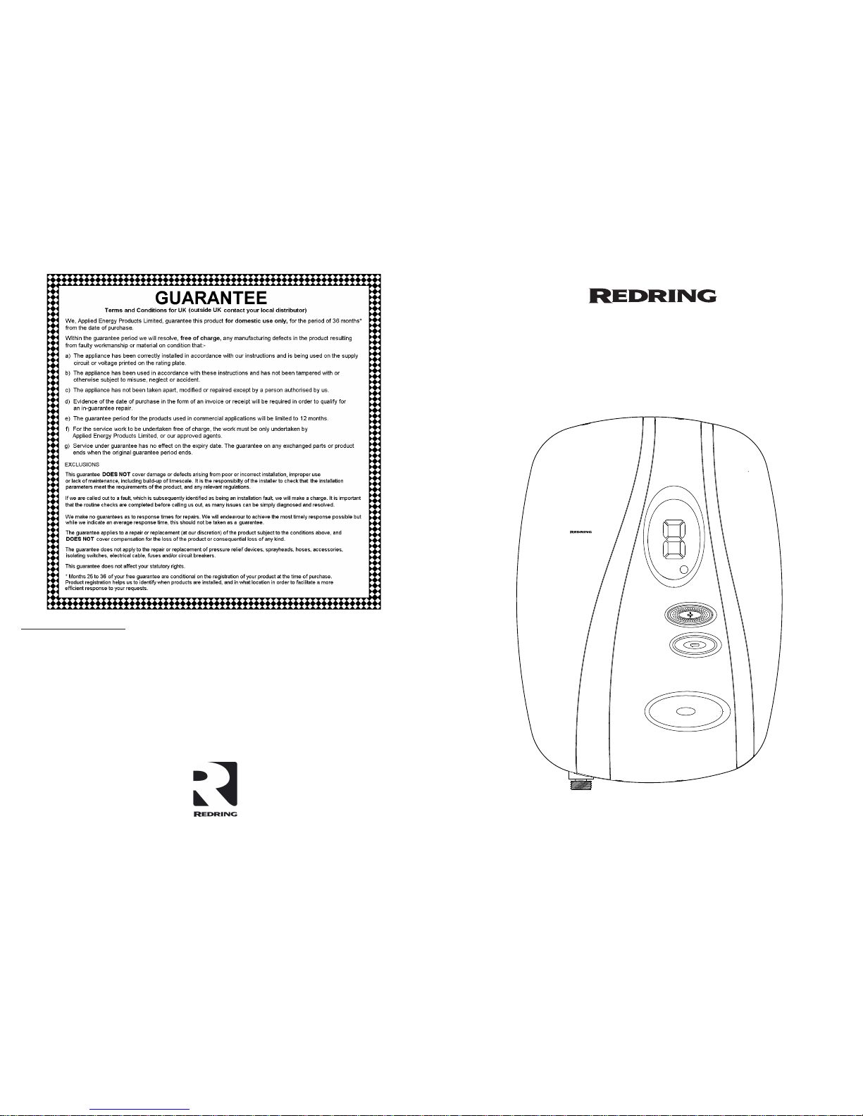
Website: www.redring.co.uk
Thermostatic Instantaneous Electronic Shower
Handbook
24
A3:567-2300-01B
01-07-2010
2
Warmer
Cooler
Start/Stop
Temperature
Temperature
Lock
Selectronic
Premier
Warmer
Cooler
Start/Stop
Temperature
Temperature
Lock
Selectronic
Premier
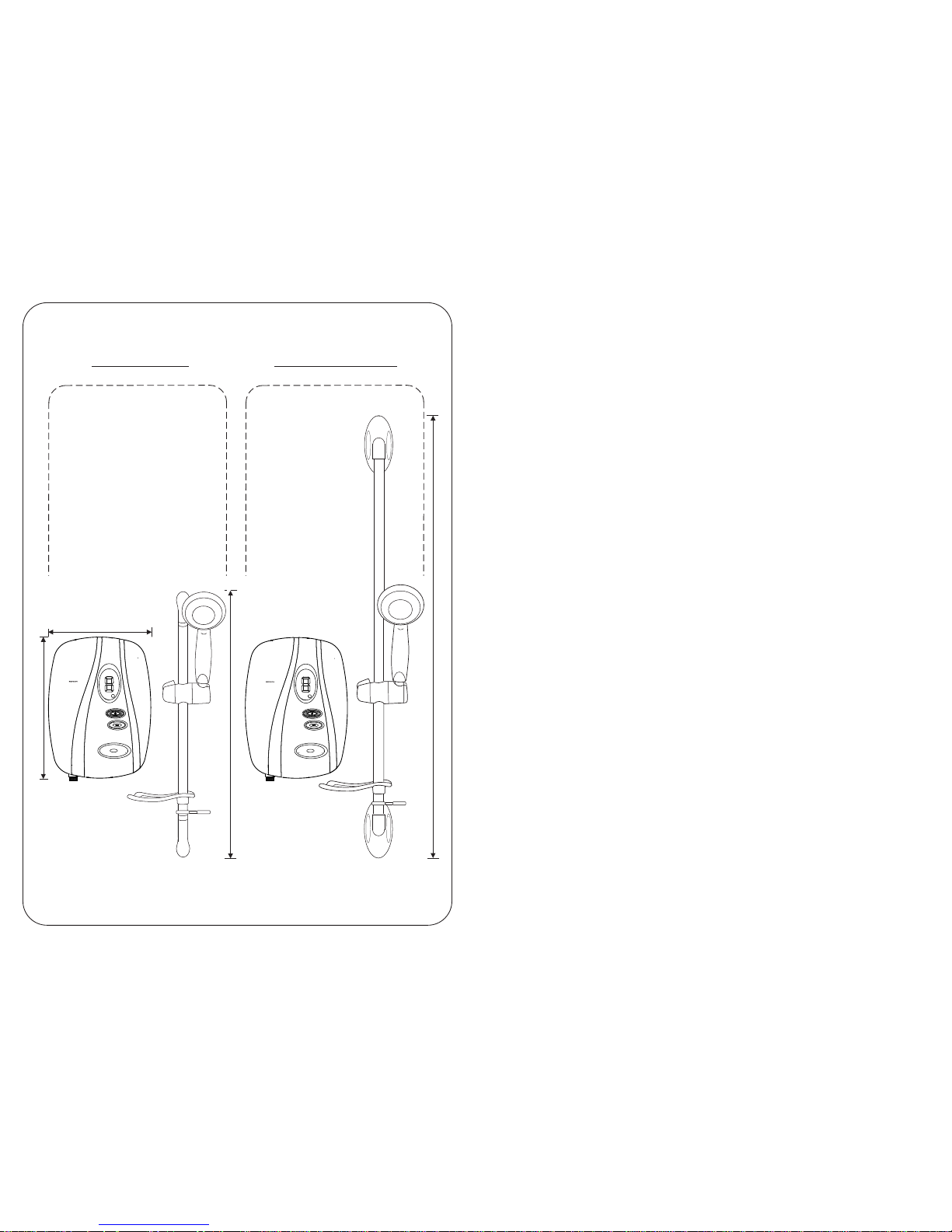
264 mm
3
6
4
m
m
6
7
4
m
m
1
12
0
m
m
Selectronic Premier Plus
(with 2m Hose)
Selectronic Premier
(with 1.25m Hose)
23
3
Installation Instructions
ALL WIRING AND INSTALLATION MUST BE
SUPERVISED BY A SUITABLY QUALIFIED
PERSON.
We recommend that the installation be done in
the following sequence: -
a) Fix the shower to the wall
b) Plumbing
c) Electrical connections
d) Commissioning
Warning! Do Not Install The Shower In A
Room Where It May Be Subject To Freezing
a) Fix The Shower To The Wall
(To assist, a mounting template is printed on
the shower carton - “Selectronic-Plus” only)
When deciding where to place the unit a few
things need to be taken into consideration: -
1) The unit must not be mounted directly in
the path of the spray from the handset
2) The handset could be used over a sink for
hair washing.
3) The handset does not come into contact
with the used water in the cubicle, bath or
basin.
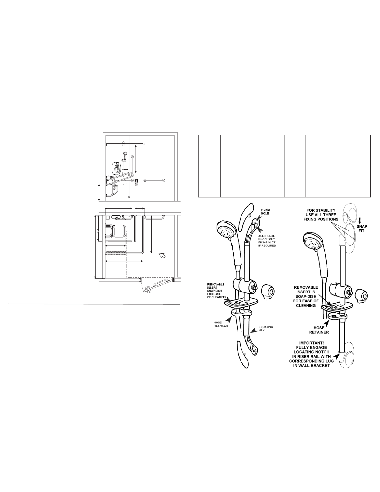
A hose retainer is supplied with the
Accessories (See Diagrams 25 & 26).
4) The unit can be mounted at a lower level for
less able users combined with optional
extended hose and riser rail.
The installation must comply with BS 8300:
2001.(Design of buildings and their
approaches to meet the needs of disabled
people. Code of practice).Remembering to
Adhere to point 1.
5) Choose a flat piece of wall to avoid the
possibility of distorting the backplate and
making the front cover a poor fit.
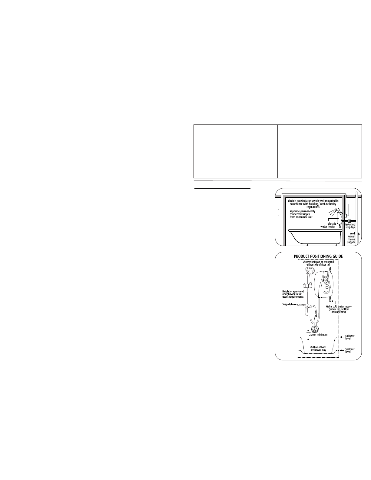
A TYPICAL INSTANTANEOUS ELECTRIC SHOWER INSTALLATION
User Information
Product Dimensions
How To Use Your Shower
How Your Shower Works
Handset Operation
Routine Maintenance
Periodical Maintenance
Trouble Shooting (User)
BEAB Care Wash Scheme
Guarantee
Contents
Installer Information;-
Product Dimensions
Installation Instructions
Plumbing Connections
Electrical Connections
Changing The Operation Mode
Templock/Normal
Changing ‘DIP Switch’ Default Setting
Commissioning
Trouble Shooting (Installer)
BEAB Care Wash Scheme
Spares
Page Page
2
3
5
7
9
9
11
19
20
21
2
12
15
17
17
18
18
21
24
22
4
Remove the four cover screws and lift the
cover off.
Remove the four inlet cover screws and remove
inlet cover - also the two side access trimplate
section screws and remove complete with seal.
Hold the shower vertically against the wall and
mark the top hole first.
Drill the hole to take the rawl plug provided
(taking care to keep dust away from the
shower).
Put the top screw in first leaving it proud by
5mm approximately. The shower can now be
hung on this screw.
Position the shower so that it is vertical then
mark and drill the other two holes. Then fix the
Shower to the wall.
Assemble the accessories as shown in
Diagram 25 (or 26 for ‘Plus’ model Accessories).
Fix the riser rail with screws provided.
The fixing holes are revealed by removing the
plastic fronts.
Note: For “Plus model accessories” ensure that
the notch in the riser rail is fully engaged into
the corresponding lug in the wall bracket. This
has been made a firm fit to aid stability and stop
rotation.
Having determined the direction of the inlet
water mains supply and cable approach for
the installation (Top, Bottom, or Rear or any
combination) - it is necessary to remove the
appropriate section inserts. See Plumbing
Connections and Electrical Installation
sections (Pages 5 and 7) for detailed guidance.
480
1
000
Handset Height Adjustment
Drop-down rail on side wall
Alarm Pull Cord
Back
Rest
Elevation
650
1500x1500 Wheelchair Turning Space
Towel / Grab Rail
Floor
Drain
T
i
p
Up
S
e
a
t
Shower Curtain
1200
1
2
0
0
5
0
0
3
5
0
Drop-down
Rail
850
300
2
0
0
0
Shower Riser
Rail
Fall of Floor
Plan
Shower
Unit
All measurements shown are in millimetres. Drawing sizes are
not to scale. Shower model shown is a Selectronic Premier Plus.
Typical guideline dimensions used for
less- abled bathroom installations
21
Spares (Ring 0844 372 7750 UK ONLY)
Description
Triac PCB
Flow Valve Assy (No Outlet)
Valve Stepper Motor
Flow Transducer
Front Cover Complete
Heat Exchanger 8.5kW
Heat Exchanger 9.5kW
Heat exchanger 10.8kW
Thermal Cut-Out c/w Cables
Outlet Connector c/w Temp Sensor
Cable/Pipe Entry Set
PRV Housing Complete
Part No,
93594102
93594104
93594105
93594117
93594135
93594136
93594137
93594138
93594139
93594140
93594141
93594142
Description
Main Logic Board
Inlet Filter Housing Complete
Backplate Trimplate
Backplate Side Section
6-Mode Handset
1.25m Long Chrome Shower Hose
2m Long Chrome Shower Hose
Wall Bracket Set (Std Models)
Wall Bracket Set (Plus Models)
22mm x 455mm Bright Riser Rail
22mm x 1m Bright Riser Rail
Height Adjuster Assy
Part No.
93594143
93594144
93594145
93594146
93593578
93797641
93550865
93593522
93550834
93593526
93550864
93593580
Diagram 25 Diagram 26
Please Note:- The fitting of all spares should be supervised by a suitably qualified person
 Loading...