

R
LWSS STAINLESS STEEL
UNVENTED WATER STORAGE HEATER
INSTALLATION
COMMISSIONING
MAINTENANCE
THIS UNIT IS SUPPLIED BY
APPLIED ENERGY PRODUCTS LTD
TEL: 08709 000430
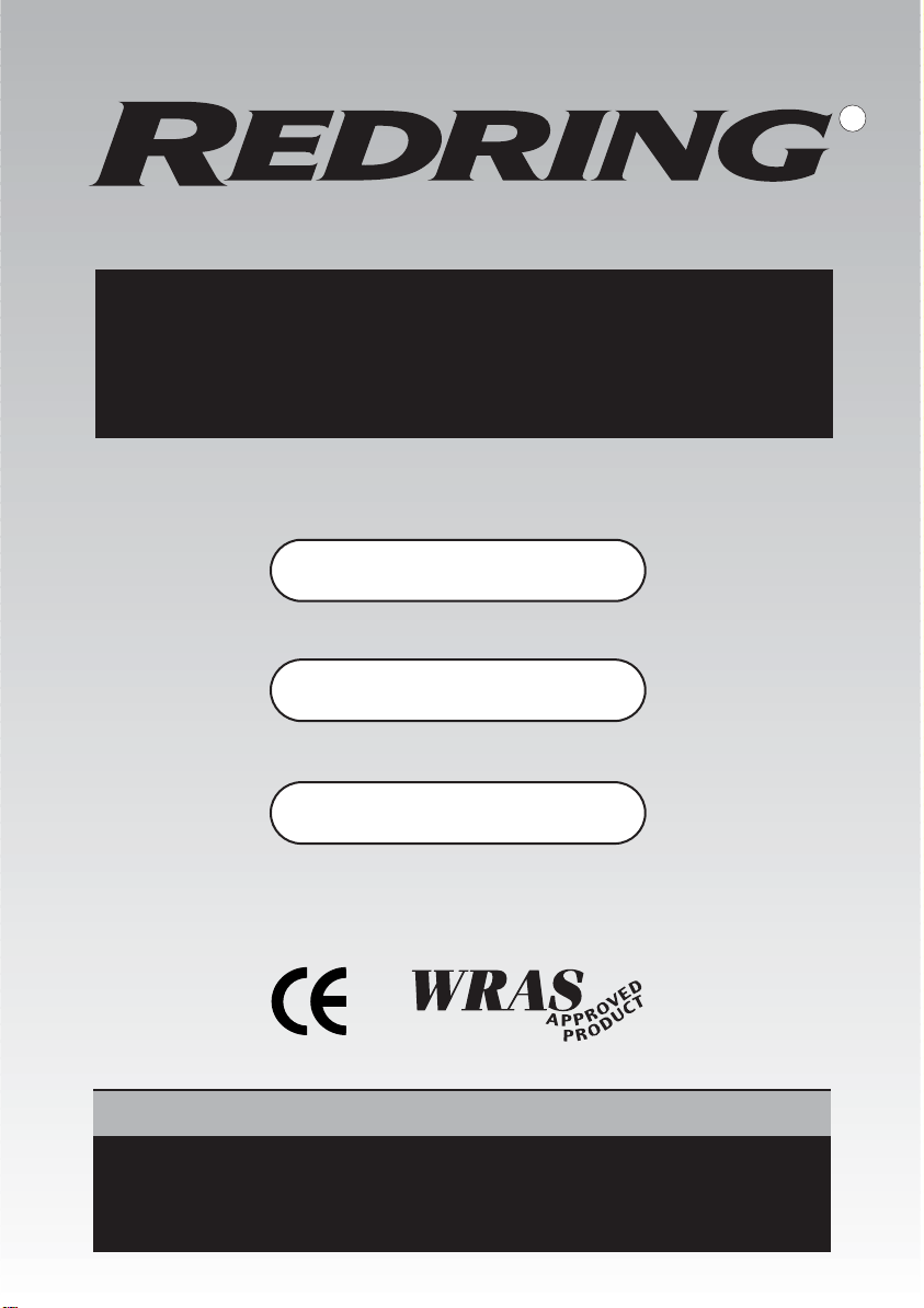
PRESSURE AND
TEMPERATURE
RELIEF VALVE
INSULATION
COLD MAINS
VIA GROUPSET
HOT DOMESTIC
WATER
IMMERSION
HEATERS
EXPANSION
VESSEL
(SUPPLIED LOOSE)
APPLIED ENERGY PRODUCTS LTD
PRESSURE AND
TEMPERATURE
RELIEF VALVE
INSULATION
COLD MAINS
VIA GROUPSET
HOT DOMESTIC
WATER
PRIMARY
TAPPINGS
DUAL
THERMOSTAT
IMMERSION
HEATER
EXPANSION
VESSEL
(SUPPLIED LOOSE)
STAINLESS STEEL UNVENTED HOT WATER STORAGE UNITS
Please read the following carefully before installation of the product. You should be competent to install
the unvented system as defined by the regulations. Special attention must be paid to maintenance and
service.
Please keep the unit packaged until you are ready to commence installation. Store the unit in a dry area,
keep it vertical and ensure that all safety components are kept in the box.
IT IS A REQUIREMENT THAT THIS UNIT IS SERVICED AND MAINTAINED ANNUALLY – THE BENCHMARK
LOG BOOK MUST BE COMPLETED AND UPDATED. FAILURE TO DO SO WILL INVALIDATE GUARANTEES.
THE DIRECT & INDIRECT UNITS
DIRECT
INDIRECT
INSTALLING THE LWSS UNIT
Choose a flat even surface. Wooden bearers are not essential as the unit sits on a ring stand. The unit
must be installed vertically.
Please install in an area that will be accessible in the future. When first fixing take into account that
the connections and controls will be front facing to facilitate access.
Check that the floor will support the unit when it is full of water. See page 14 for weights.
COLD FEED
Minimum mains pipework of 25mm MDPE or 22mm copper is advised. If 15mm copper or 1/2" lead is
the only mains feed then the decision to install rests with the installer or specifier of the product. Flow
rates will be compromised, even at appropriate pressures, ensure that you have at least 18 litres per
minute at the bath tap. Maximum inlet pressure is 12 bar.
If multiple bath filling or showering is required, mains feed may need to be 32mm MDPE or 28mm copper.
The unit operates at 3 bar and pressures from 2 bar upwards are suitable. Lower pressure will result in
a fall in flow rate. A flow rate of 20 litres per minute is a minimum requirement for single bath
applications and must rise proportionately for greater demands.
1
Please also take into account any fitting that could restrict flow such as water meters, softeners etc.
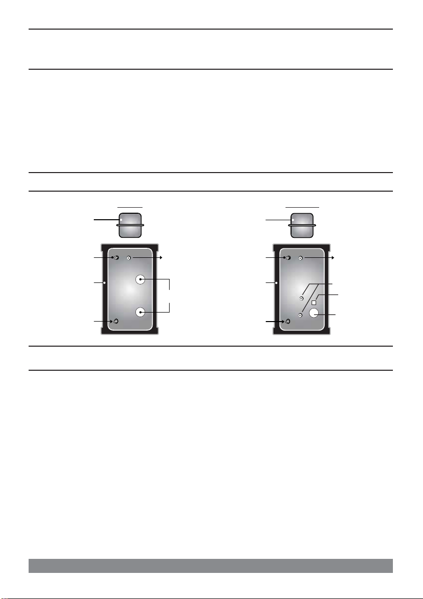
PRESSURE REDUCING
VALVE/FILTER
NON RETURN VALVE PRESSURE GAUGE
EXPANSION VESSEL
(OPTIONAL)
DRAIN POINT
EXPANSION VALVE
COLD TAPS
COLD FEED
22mm
EXPANSION
VALVE
22mm
TUNDISH
15mm
15mm
PRESSURE AND
TEMPERATURE
RELIEF VALVE
Connection to the unit – Use 22mm compression for all connections. Use gunmetal, DZR or brass fittings,
noting local water conditions.
COLD MAINS COMPONENT LAYOUT
No valve is to be fitted between the expansion valve and the cylinder, except a drain point.
It is recommended that a stop cock is fitted to the above to facilitate servicing. Install before the
pressure reducing valve. Always fit a drain tap in an appropriate position for drain down as low as
possible.
DON’T USE MONOBLOC MIXERS IF THE COLD SERVICE IS UNEQUALISED AS IT WILL BACK – PRESSURISE
THE UNIT AND RESULT IN DISCHARGE.
DISCHARGE
Both the pressure and temperature
relief valve fitted to the unit and
the expansion valve supplied loose
must be arranged to comply with
G3 regulations and each discharge
into an open (visible) tundish.
A 300mm vertical drop of 22mm
diameter pipe must be fitted to the
tundish.
NB: THE TUNDISH AND DRAIN
MUST BE POSITIONED AWAY FROM
ELECTRICAL DEVICES.
ALWAYS CONSULT THE REGULATIONS!
IMPORTANT: Discharge arrangements are the responsibility of the installer and reference to current
building regulations should always be made. Applied Energy Products Ltd. offers the foregoing as
guidelines only.
The main purpose of discharge pipework is to allow full flow from relief valves to be accumulated and
safely routed to a point outside the building at low level.
2

GUIDANCE NOTES
TUNDISH DISCHARGE
The unit is supplied with two mechanical safety devices. An expansion relief valve, supplied loose, and
a temperature/pressure relief valve fitted to the unit, both discharging into a tundish (supplied loose).
Discharge pipes must be left open to atmosphere, not blocking the tundish.
The responsibility for supplying and fitting the discharge pipe from the tundish is that of the certified
installer. In general, installation practice should be in accordance with the approved document G3 of
schedule 1 of the building regulations 1991, VIZ:
3.9 The discharge pipe from the tundish should terminate in a safe place where there is no risk to
persons in the vicinity of the discharge, be of metal and:
a Be at least one pipe size larger than the nominal outlet size of the safety device unless its total
equivalent hydraulic resistance exceeds that of a straight pipe 9m long i.e discharge pipes between
9m and 18m equivalent resistance length should be at least larger than the nominal outlet size of
the safety device, between 18m and 27m at least 3 sizes larger, and so on. Bends must taken into
account in calculating the flow resistance. See Diagram and table on page 6.
bHave a vertical section of pipe at least 300mm long, below the tundish before any elbows or bends
in the pipework.
c Be installed with a continuous fall.
dHave discharges visible at both the tundish and the final point of discharge but where this is not possible or
practically difficult there should be clear visibility at one or other of these locations. Examples of acceptance
discharge arrangements are:
d.1Ideally below a fixed grating and above the water seal in a trapped gully.
d.2 Downward discharges at a low level; i.e. up to 100mm above external surfaces such as car parks, hard
standings, grassed areas etc. are acceptable providing that where children may play or otherwise come
into contact with discharges, a wire cage or similar guard is positioned to prevent contact, whilst
maintaining visibility.
Continued...
3

GUIDANCE NOTES
d.3Discharges at high level; e.g. in to metal hopper and metal down pipe with the end of the discharge
pipe clearly visible (tundish visible or not) or onto a roof capable of withstanding high temperature
discharges of water and 3m from any plastic guttering systems that would collect such discharges
(tundish visible).
d.4Where a single pipe serves number of discharges, such as in a block of flats, the number served should
be limited to not more than 6 systems so that any installation can be traced reasonably easily. The
single common discharge pipe should be at least one pipe size larger than the largest individual
discharge pipe to be connected. If unvented hot water storage systems are installed where discharges
from safety devices may not be apparent i.e. in dwellings occupied by blind, infirm or disabled people,
consideration should be given to the installation of an electronically operated device to warn when
discharge takes place.
NOTE: The discharge will consist of scalding water and steam. Asphalt, roofing felt and non-metallic
rainwater goods may be damaged by such discharges.
4
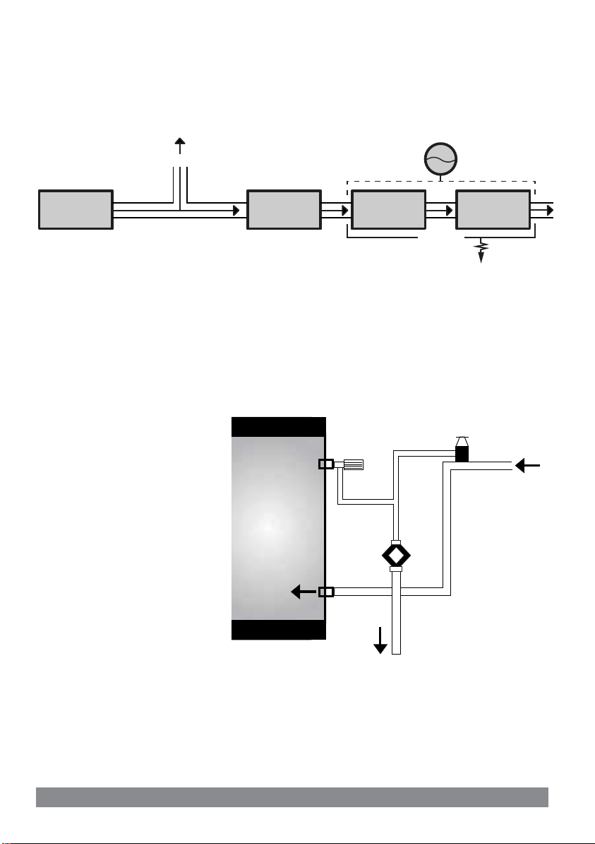
GUIDANCE NOTES - TYPICAL DISCHARGE PIPE ARRANGEMENT
SAFETY DEVICE
(e.g. TEMPERATURE RELIEF VALVE)
500mm MAXIMUM
300mm
MINIMUM
TUNDISH
FIXED GRATING
METAL DISCHARGE PIPE (D1)
FROM TEMPERATURE RELIEF
TO TUNDISH
METAL DISCHARGE PIPE (D2)
FROM TUNDISH,
WITH CONTINUOUS FALL
(SEE 3.9d i-iv & TABLE 1)
DISCHARGE BELOW
FIXED GRATING
(3.9d GIVES ALTERNATIVE POINTS
OF DISCHARGE)
TRAPPED GULLY
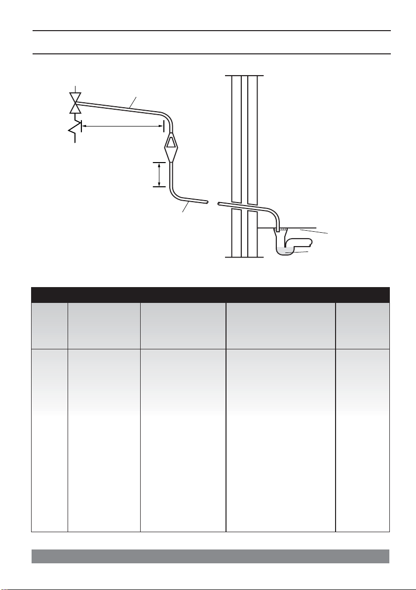
SIZING OF D2 COPPER DISCHARGE PIPE FOR COMMON TEMPERATURE RELIEF VALVE OUTLET SIZES
VALVE
OUTLET
SIZE
MINIMUM SIZE OF
DISCHARGE PIPE
(D1)
MINIMUM SIZE OF
DISCHARGE PIPE (D2)
FROM TUNDISH
MAXIMUM RESISTANCE
ALLOWED, EXPRESSED AS A
LENGTH OF STRAIGHT PIPE
(I.E. NO ELBOWS OR BENDS)
RESISTANCE
CREATED BY
EACH ELBOW
OR BEND
1
/
G
2
G3/
4
G1
15mm
22mm
28mm
22mm
28mm
35mm
28mm
35mm
42mm
35mm
42mm
54mm
5
up to 9m
up to 18m
up to 27m
up to 9m
up to 18m
up to 27m
up to 9m
up to 18m
up to 27m
0.8m
1.0m
1.4m
1.0m
1.4m
1.7m
1.4m
1.7m
2.3m

WORKED EXAMPLE:
The example below is for a G1/2 temperature relief valve with a discharge pipe (D2) having 4 No.
elbows and length of 7m from the tundish to the point of discharge.
From Table 1
•Maximum resistance allowed for a straight length of 22mm copper discharge pipe (D2) from a
G1/2 temperature relief valve is 9.0m.
• Subtract the resistance for 4 No. 22mm elbows at 0.8m each = 3.2m
•Therefore the maximum permitted length equates to 5.8m.
• 5.8m is less than the actual length of 7m therefore calculate the next largest size.
•Maximum resistance allowed for a straight length of 28mm pipe (D2) from a G1/2 temperature
relief valve equates to 18m.
• Subtract the resistance for 4 No. 28mm elbows at 1.0m each = 4.0m
•Therefore the maximum permitted length equates to 14m.
•As the actual length is 7m, a 28mm (D2) copper pipe will be satisfactory
INSTALLATION
HOT WATER OUTLETS
Dynamic pressure always drops across a system when more than one outlet is opened.
The unit has a working pressure of 3 bar.
Good system design should take this into consideration & pipe sizing should be in line with current
good practice.
In hard water areas a reduced operating temperature will help to prevent premature scaling.
EXPANSION VESSEL
The vessel (supplied loose) screws onto the top of the unit. It is sized appropriately and includes
some allowance for pipework. Check the charge is at 3.0 bar before commissioning.
The expansion vessel can also be fitted remotely between the unit and the check valve on the cold
supply or by adaptor to the top female fitting on the cylinder.
PRIMARY CIRCUITS
The maximum primary pressure is 3.5 bar.
The boiler must have a mechanical high-limit thermostat.
Solid fuel boilers cannot be used
If the primary circuit is sealed, an additional expansion vessel must be fitted.
If a secondary circuit is connected an additional expansion vessel may be required.
6
2 PORT
VALVE
NB: By-pass must be fitted
in accordance with boiler
manufacturer's instructions
BOILER
CIRCS
22mm
ELECTRICAL CONNECTIONS
Immersion heaters are rated 3kw at 240v (2.76kw at 230v), incolloy elements, with a thermal energy cutout, and must be connected via double pole switches with a 3mm contact gap separation. Appropriate
wiring for the electrical load must be used. The twin immersion heaters supplied with direct units can
be switched to utilise low tariff electricity supply. Do not switch on until the unit is full of water.
Immersion heaters are supplied fitted in the body of the unit. Always ensure that the joints are
watertight on commissioning. The thread is non-standard. Order replacements using reference number
on page 14. Do not fit an immersion heater without a high limit thermostat. Immersion heaters fitted
are designed for domestic use only, either utilising low tariff electricity and occasional boost or for
switched periods during the day.
Immersion heaters must meet BS EN 60730-2-1.
Units must be earth bonded.
The fuse rating for 6kw loading is 25 amps, for the 3kw (indirect) model the fuse rating is 13 amps.
ALWAYS CONSULT THE REGULATIONS!
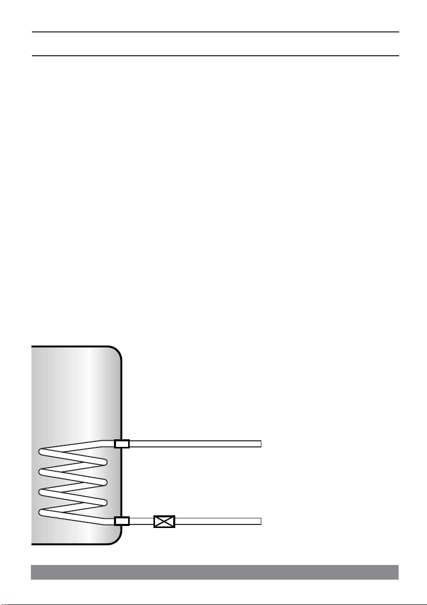
INDIRECT INSTALLATIONS
The indirect pattern products are supplied with dual thermostats with
sensing probes and with a motorised two port valve.
The thermostat has to be wired in order to control the water temperature
in the system and, if the high limit is tripped, to operate the two port
valve in such a way as to route primary water back to the boiler and isolate
the cylinder (see diagram).
7
 Loading...