

Page 1
The engine exhaust from this product
contains chemicals known to the State
of California to cause cancer, birth
defects or other reproductive harm.
WARNING
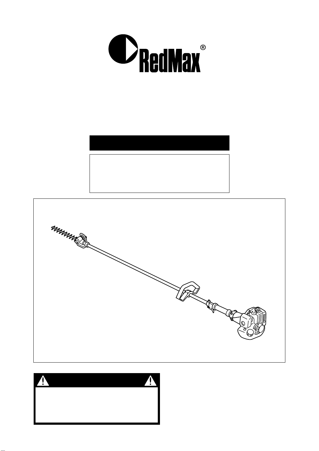
OWNER/OPERATOR MANUAL
LONG REACH TRIMMER
6782-13000(906)
LRT2300
Thank you for purchasing a RedMax
product.
Before using our trimmer, please read
this manual carefully to understand the
proper use of your unit.
Page 2
Read this manual carefully to understand all
safety precautions, controls, proper operation
and maintenance of your RedMax long reach
trimmer. Failure to do so could result in
serious injury.
Instructions labeled as shown at left, concern critical steps or
procedures which must be followed in order to prevent accidents
which could lead to serious bodily injury or death.This mark is
used to indicate instructions which must be followed without
exception.
Instructions labeled as shown at left concern steps or procedures
which, if not followed correctly, could lead to mechanical failure,
breakdown, or damage.
Used to label supplementary instructions designed to provide
hints or directions useful in the use of the product.
WARNING
IMPORTANT
NOTE
SAFETY FIRST
Instructions contained in warnings within this manual and warning seals marked
with a symbol on the long reach trimmer concern critical points which must
be taken into consideration to prevent possible serious bodily injury, and for this
reason you are requested to read all such instructions carefully and follow them
without fail.
Note that there may be times when warning seals peel off or become soiled and
impossible to read. If this happens, you should contact the dealer from which
you purchased the product to order new seals and affix the new seal(s) in the
required location(s).
■ Notes on types of warnings
Page 3

CONTENTS
SAFETY PRECAUTIONS · · · · · · · · · · · · · · · · · · · · · · · · · · · · · 3
OPERATOR
WORKING CONDITION
AVOID NOISE PROBLEM
AVOID CHANCES OF DAMAGE
WARNING LABELS
SPECIFICATIONS · · · · · · · · · · · · · · · · · · · · · · · · · · · · · · · · · · · 8
SET UP · · · · · · · · · · · · · · · · · · · · · · · · · · · · · · · · · · · · · · · · · · · · 9
FUEL · · · · · · · · · · · · · · · · · · · · · · · · · · · · · · · · · · · · · · · · · · · · · 10
FUEL MIX
MIXING FUEL
FUELING
OPERATION · · · · · · · · · · · · · · · · · · · · · · · · · · · · · · · · · · · · · · · 11
STARTING ENGINE
ADJUSTING IDLE SPEED
STOPPING ENGINE
MAINTENANCE · · · · · · · · · · · · · · · · · · · · · · · · · · · · · · · · · · · 13
CHECK THE TRIMMER
BLADE
GEAR CASE
AIR CLEANER
FUEL FILTER
SPARK PLUG
MUFFLER
SPARK ARRESTER
STORAGE · · · · · · · · · · · · · · · · · · · · · · · · · · · · · · · · · · · · · · · · 17
PARTS LIST · · · · · · · · · · · · · · · · · · · · · · · · · · · · · · · · · · · · · · · 18
Page 4

INFORMATION
This machine is equipped with an Overload Cancellation
Mechanism.
When the cutting blades have got into metal wires or those
twigs difficult to cut, the mechanism acts as a shock
absorber, and protects the drive gears and the blades from
severe reaction which could give damage to those parts.
When the blades are frequently caught by twigs, please
check the following points:
1. Size of the twigs. NEVER TRY TO CUT TWIGS
THICKER THAN 3/16”.
2. Condition of the blade edges. REPLACE THE WORN
OUT BLADES.
For the detail of the mechanism, please see below.
Thank you for choosing our product.
Page 5
■
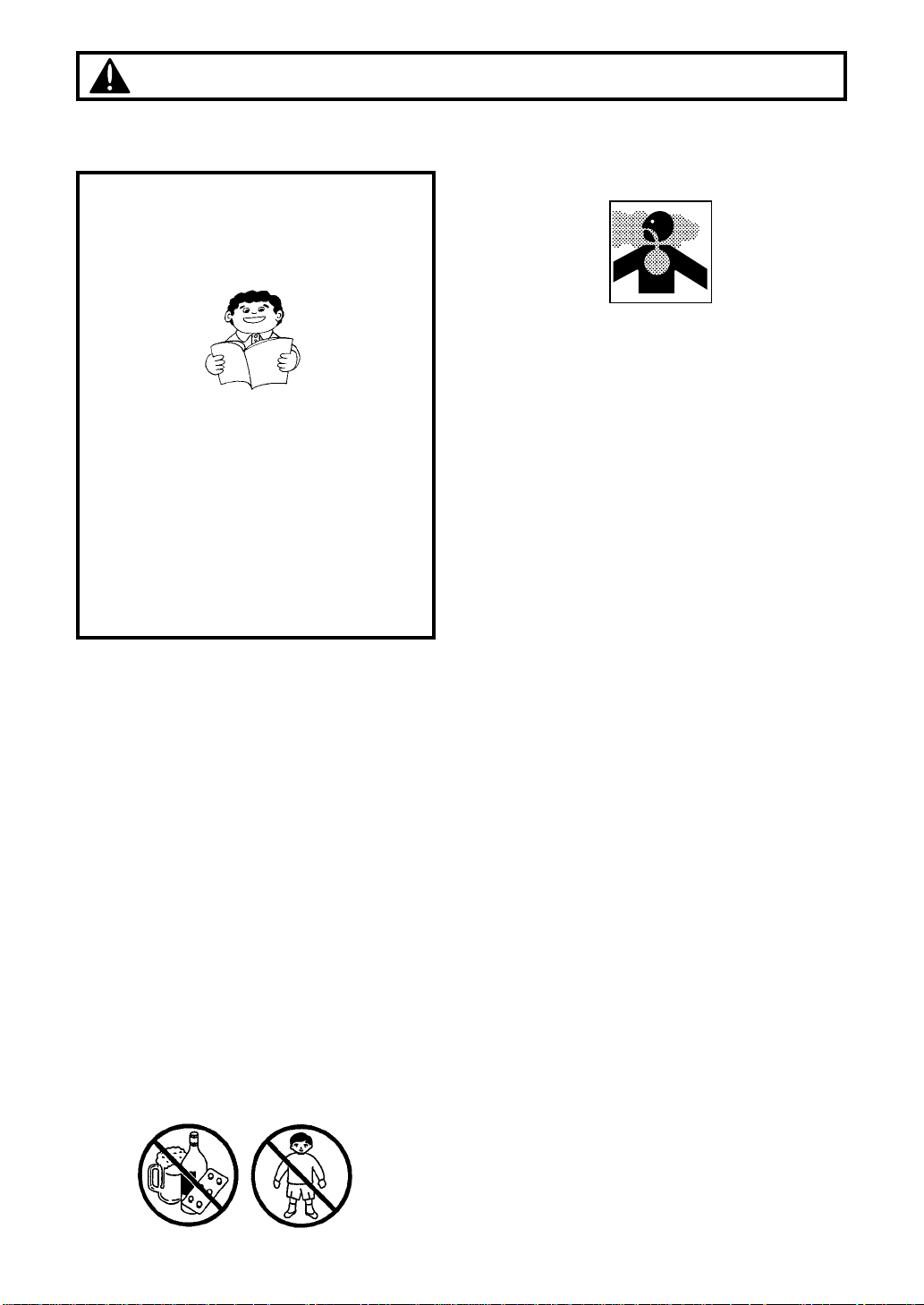
In order to ensure proper and safe
operation of your trimmer
•Read this long reach trimmer
Owner/Operator Manual carefully. Be
sure you understand how to operate this
unit properly before you use it. Failure to
do so could result in serious injury.
•Be sure to keep this manual handy so that
you may refer to it later whenever any
questions arise. Also note that you are
requested to contact the dealer from
whom you purchased the product for
assistance in the event that you have any
questions which cannot be answered
herein.
• Always be sure to include this manual
when selling, lending, or otherwise
transferring the ownership of this product.
• This product has been designed for use in
trimming leaves and branches from trees
and hedges, and it should never be used
for any other purpose since doing so could
result in unforeseen accidents and injuries
occurring.
• This product is equipped with extremely
sharp blades, and when used improperly
these blades can be extremely dangerous.
For this reason, you should never use this
trimmer when under the influence of
alcohol, when suffering from exhaustion or
lack of sleep, when suffering from
drowsiness as a result of having taken cold
medicine, or at any other time when a
possibility exists that your judgment might
be impaired or that you might not be able to
operate the trimmer properly and in a safe
manner. Also be sure never to allow
children or anyone unable to fully
understand the directions given in this
manual to use this trimmer.
Safety Precautions
• Avoid running the engine indoors. The
exhaust gases contain harmful carbon
monoxide.
•Never use your trimmer under
circumstances like those described below:
1. When the ground is slippery or when
other conditions exist which might make
it not possible to maintain a steady
posture while using the trimmer.
2.At night, at times of heavy fog, or at any
other times when your field of vision
might be limited and it would be difficult
to gain a clear view of the area where
the trimmer is to be used to ensure
safety.
3. During rain storms, during lightning
storms, at times of strong or gale-force
winds, or at any other times when
weather conditions might make it unsafe
to use this product.
• When using this product for the first time,
before beginning actual work, take the
trimmer to a wide, clear, open space, turn
on the power, and practice handling the
trimmer until you are sure that you will be
able to handle in it properly in actual
operation.
• Lack of sleep, tiredness, or physical
exhaustion results in lower attention spans,
and this in turn leads to accidents and
injury. When planning your work schedule,
allow plenty of time to perform the work of
trimming and allow plenty of time for rest.
Limit the amount of time over which the
trimmer is to be used continuously to
somewhere around 30~40 minutes per
session, and take 10~20 minutes of rest
between work sessions. Also try to keep
the total amount of work performed in a
single day under 2 hours or less.
❲3❳
Page 6
❲4❳
Safety Precautions
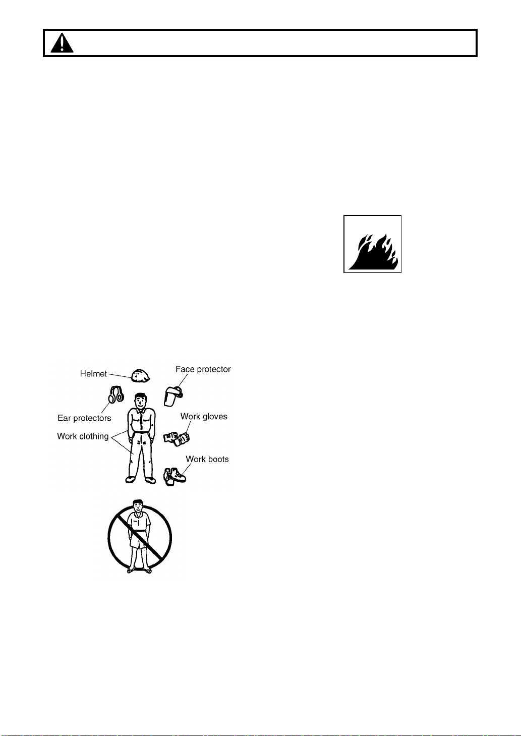
■Work gear and clothing
• When using your trimmer, always be sure
to wear strong, durable, work clothing;
shirts should be long-sleeved shirts and
pants should be full-length pants reaching
down to the ankles.
• Always be sure to wear and helmet and
face protector when using your trimmer.
• When using your trimmer, always be sure
to wear thick work gloves to protect your
hands and non-slip-sole work boots to
prevent you from slipping. Never use your
trimmer when wearing pants with loose
cuffs, when wearing sandals, or when
barefoot.
• When using your trimmer for an extended
period of time, you should wear ear
protectors to protect yourself from loss of
hearing from overexposure to high levels of
sound.
■Warnings considering handling of fuel
• The engine of the RedMax® trimmer is
designed to run on a mixed fuel which
contains highly flammable gasoline. This
fuel is highly flammable and you should
never store cans of fuel or refill the tank of
the trimmer in any place where there is a
boiler, stove, wood fire, electrical sparks,
welding sparks, or any other source of heat
or fire which might ignite the fuel.
• Smoking while operating the trimmer or
refilling its fuel tank is extremely
dangerous. Always be sure to keep lit
cigarettes away from the trimmer at all
times.
• When refilling the tank always turn off the
engine first and take a careful look around
to make sure that there are no sparks or
open flames anywhere nearby before
refueling.
• If any fuel spillage occurs during refueling,
always be sure to use a dry rag to wipe any
fuel which has been spilled onto the
trimmer before turning the engine back on
again.
• After refueling, screw the fuel cap back
tightly onto the fuel tank and then carry the
trimmer to a spot 10 feet or more away
from where it was refueled before turning
on the engine.
Page 7
❲5❳
Safety Precautions
■ Things to check before using your
trimmer
•Before beginning work, look around
carefully to get a feel for the shape of the
land, the trees, hedges, or bushes to be
trimmed, and whether or not there are any
obstacles which might get in the way while
working, and remove any obstacles which
can be cleared away before beginning
work.
•The area within a perimeter of 45 feet of the
person using the trimmer should be
considered a hazardous area into which no
one should enter while the trimmer is in
use, and when necessary yellow warning
rope, warning signs, or some other form of
warnings should be placed around the
perimeter of the area. When work is to be
performed simultaneously by two or more
persons, care should also be taken to
constantly look around or otherwise check
for the presence and locations of other
people using trimmers within the work area
so as to maintain a distance between each
person sufficient to ensure safety.
•Before beginning work, each component of
the trimmer should be checked to make
sure that it is in proper working order and to
make sure that there are no loose screws
or bolts, fuel leaks, ruptures, dents, or any
other problems which might interfere with
safe operation. Be especially careful at this
time to check that there is nothing wrong
with the blades or with the joints by which
the blades are attached to the trimmer.
• Never use the trimmer when the blades
have been worn down severely or when
there is any sort of damage which has
occurred to the blade mechanism.
• Check to make sure that the handle grip
and the protective cover have not come
loose before using the trimmer.
■ Things to check before starting up the
engine
• Take a careful look around to make sure
that no obstacles exist within a perimeter of
15 feet or less around the trimmer before
starting the engine.
• The RedMax trimmer is equipped with a
centrifugal clutch mechanism which causes
the cutting blades to begin to rotate as
soon as the engine is started by putting the
throttle into the start position. When starting
the engine, place the body of the trimmer
onto the ground in a flat clear area and
hold it firmly in place so as to ensure that
neither the blades nor the throttle come into
contact with any obstacles when the engine
starts up.
•Never place the throttle into the high speed
position when starting the engine.
•After starting up the engine, check to make
sure that the blades stop rotating when the
throttle is moved fully back to its original
position. If the blades continue to rotate
even after the throttle has been moved fully
back, turn off the engine and take the unit
to your authorized Red Max servicing
dealer for repair.
■AVOID NOISE PROBLEM
Check and follow the local regulations
as to sound level and hours of
operations for long reach trimmer.
• In general, operate trimmers between
8a.m.and 5p.m.on week days and 9a.m.to
5p.m.weekends. Avoid using trimmer late
at night and/or early in the morning.
NOTE
Page 8

Safety Precautions
■ Things to be careful about when using
your trimmer
•When using your trimmer, grip the handles
of the trimmer firmly with both hands, place
your feet slightly apart (slightly further apart
than the width of your shoulders) so that
your weight is distributed evenly across
both legs, and always be sure to maintain a
steady, even posture while working.
• Maintain the speed of the engine at the
level required to perform trimming work,
and never raise the speed of the engine
above the level necessary.
• Always be sure never to allow other
persons to come within the work area while
trimming, as doing so might expose them
to the danger of being hit by falling
branches as they are cut.
• Be especially careful not to slip if it is
raining or if rain has just stopped, as the
ground is likely to be slippery at such times.
• If a branch or other object gets caught in
the blades during operation, always be
sure to turn off the engine before removing
the object.
• To protect yourself against injury from
falling branches, always be sure to wear
the required safety equipment, and be
careful when working to watch to see in
which direction branches are moving and
falling so as to avoid being hit by falling
branches.
•If someone calls out or otherwise interrupts
you while working, always be sure to turn
off the engine before turning around.
• Keep operation area clear of all persons,
particularly small children and pets. Injury
may result from flying debris.
• Never touch the spark plug or
plug cord while the engine is in
operation. Doing so may result
in being subjected to an
electrical shock.
• Never touch the muffler, spark
plug, or other metallic parts of
the engine while the engine is
in operation or immediately
after shutting down the engine.
These metallic parts reach high
temperatures during operation and doing
so could result in serious burns.
• When you finish trimming in one location
and wish to continue work in another spot,
turn off the engine, place the protective
cover over the blades, and turn the trimmer
so that the blades face away from your
body before carrying it to the new location.
• Never transport the trimmer over rough
roads over long distances without first
removing all fuel from the fuel tank, as
doing so might cause fuel to leak from the
tank as a result of shocks absorbed during
transport.
■ Notes on care and maintenance of your
trimmer
•In order to maintain your trimmer in proper
working order, perform the maintenance
and checking operations described in this
manual at regular intervals. In the event
that any parts must be replaced or any
maintenance or repair work not described
in this manual must be performed, please
contact a representative from the store
nearest RedMax authorized servicing
dealer for assistance.
• Under no circumstances should you ever
take apart the trimmer or alter it in any way.
Doing so might result in the trimmer
becoming damaged during operation or the
trimmer becoming unable to operate
properly.
•Always be sure to turn off the engine before
performing any maintenance or checking
procedures.
•When sharpening, removing, or reattaching
the blades, be sure to wear thick, sturdy
gloves and use only proper tools and
equipment to prevent injury.
• When replacing blades or any other parts
or when replacing the oil or any lubricants,
always be sure to use only RedMax
products or products which have been
certified by RedMax for use with the
RedMax trimmer.
❲6❳
Page 9

Safety Precautions
■Taking care of warning labels
1.Always keep warning labels clean and free of scratches which might make them illegible or
difficult to read.
2. If the warning labels provided with your trimmer become soiled, peel off, or otherwise
become illegible or difficult to read, order new labels from the RedMax authorized servicing
dealer where you purchased your trimmer and replace the damaged labels with new labels.
3. When applying new labels, be sure to first wipe away any dirt and dry the surface before
applying the new label in the same place as the original label.
Carefully read owner’s manual
■Handling of warning labels (Part number : 6782-13250)
Keep hands away from cutting blades
❲7❳
Handling this machine
improperly could result in
accidents causing serious
injury or death. Read this
manual carefully and practice
using the trimmer until you
are fully acquainted with all
operations and have learned
to use it correctly.
Always be careful to wear a
face protector and helmet
when using your trimmer.
Where to apply
Page 10

Specifications
MODEL LRT2300
Overall size ( L x W x H ) 92.9 x 9.6 x 8.7 in
Dry Weight w/o shoulder strap
13.2 lbs
Engine Type Air cooled 2-stroke gasoline engine
Model ZENOAH G23L
Displacement 22.5 cc
Max. output
Fuel Mixture (Gasoline 32 : Oil 1)
Carburetor Walbro Diaphragm type
Spark Plug Champion RJ6CY
Transmission
Centrifugal clutch, spiral bevel gear, cam crank
Reduction ratio 4 : 1
Cutting head Type Reciprocating Double blade
Tooth 28 teeth
Pitch 30
Effective cut width 16 in
Angle adjust range
90°(±45° from cutting head position aligned shaft)
Standard Accessories Shoulder strap 1 pc
Goggle 1 pc
Tool Kit 1 pc
Blade Cover 1 pc
❲8❳
Page 11

Set up
■MOUNTING ENGINE
1.Remove the clamp temporarily attached to
the clutch housing.
2. Push the driveshaft toward the gearcase
and rotate it by hand to check that the
driveshaft is engaged with the gears.
3. Insert the shaft tube into the clutch
housing until it bottoms. When difficult to
engage, twist the engine slightly.
4. Align the positioning holes on the clutch
housing and the shaft tube and fit the boss
on the clamp into the hole. Fasten the
clamp securely.
■INSTALLING HANDLE
Mount the handle to the shaft tube and
clamp it at your best operating position.
■CONNECTING THROTTLE WIRE
1.Remove the air cleaner cover.
2.Connect the end of the throttle wire to the
joint on the top of the carburetor.
■CONNECTING THE SWITCH CORD
• Insert the end of the cord firmly. An
improper connection may result in the
cord becoming loose during operation
or in causing the engine to fail to stop
even after the switch has been turned
off.
• Be careful never to bend the end of the
cord when connecting it.
1. Connect the terminal ends of the two
cords on the side of the engine to the
terminal ends of the two cords on the
side of the trimmer. Note that no
distinction is made between positive and
negative nodes, and that the cords may
be connected in any combination.
2. After the cords have been connected,
use the clamp located on the side of the
engine cover to fix the ends of the cords
firmly into place.
■
ATTACHING THE TRIMMING MECHANISM
1. Remove the cap on the end of the main
pipe.
2.Remove the screw screwed into the end of
the trimming mechanism.
3.Insert the end of the trimming mechanism
into the main pipe.
4. Line up the hole on the end of the
trimming mechanism into which the screw
is to be inserted with the hole on the main
pipe, and screw the screw firmly in.
5. Using a 10-mm wrench, screw in the
hexagonal bolt provided to fix the trimming
mechanism into place.
WARNING
❲9❳
Page 12

• Gasoline is very flammable. Avoid
smoking or bringing any flame or
sparks near fuel. Make sure to stop the
engine and allow it cool before
refueling the unit. Select outdoor bare
ground for fueling and move at least
3m(10ft) away from the fueling stop
before starting the engine.
■FUEL MIX
• The engine is lubricated by oil mixed into
gasoline. Prepare a mixture of unleaded,
alcohol-free gasoline and RedMax oil or an
anti-oxidant added quality oil expressly
labeled for air-cooled 2-cycle engine use.
Recommended mixing ratio is 32 : 1.
• Make sure to use gasoline with a minimum
octane number of 90 ROZ(USA/Canada :
pump octane min.87)
• Unleaded gasoline is recommended to
reduce the contamination of the air for the
sake of your health and the environment.
• Poor quality gasolines or oils may damage
sealing rings, fuel lines or fuel tank of the
engine.
• Exhaust emission are controlled by the
fundamental engine parameters and
components (eq., carburetion, ignition
timing and port timing) without addition
of any major hardware or the introduction of an inert material during combustion.
WARNING
• These engines are certified to operate
on unleaded gasoline.
■MIXING FUEL
1.Measure out the quantities of gasoline and
oil to be mixed.
2.Put some of the gasoline into a clean,
marked fuel container.
3.Pour in all of the oil, cap the container and
shake it well.
4.Pour in the rest of gasoline and shake
again for one minute.
5.Indicate the contents on outside of
container for easy identification.
DO NOT USE :
•Fuel containing no oil (raw gasoline)
may cause the engine to become
overheated and damaged.
•Gasohol may cause deterioration of rubber
and plastic parts and disruption of the
engine lubrication.
•Oil for 4-cycle engine use or water-
cooled 2-cycle engine use may cause
spark plug fouling, carbon building-up and
piston ring sticking.
•Mixed fuels which have been left unused
for a period of one month or more may
clog the carburetor or result in the engine
failing to operate properly.
■FUELING
1.Unfasten and remove the fuel cap. Put the
cap on a clean surface for dirt prevention.
2.Pour fuel into the fuel tank up to 80% of full
capacity.
3.Replace the fuel cap and tighten securely.
Spilled fuel must be wiped away from the
trimmer before starting the engine.
Fuel
❲10❳
32:1 MIXING CHART
GASOLINE gal. 1 2345
2-CYCLE OIL fl.oz 4 8 12 16 20
Page 13

■STARTING ENGINE
1. Rest the unit on a flat, firm place. Keep
the cutting head off the ground and clear of
surrounding objects as it will start rotating
upon starting of the engine.
2.Pump the primer until fuel flows out in the
clear tube.
3.Move the choke lever upward to close the
choke.
4.Shift the ignition switch to the START
position.
5.While pulling the throttle lever with the little
finger of your left hand, pull the starter
rope briskly.
IMPORTANT
Operation
Avoid pulling the rope to its end or returning
it by releasing the knob. Such actions can
cause starter failures.
6. When the engine has started, move the
choke lever gradually downward to open
the choke
7. Allow the engine to warm up for a half
minute before starting operation.
1. When restarting the engine immediately
after stopping it, leave the choke open.
2. Overchoking can make the engine hard to
start due to excess fuel. When the engine
fails to start after several attempts, open
the choke and repeat pulling the rope, or
remove the spark plug and dry it.
■STOPPING ENGINE
1. Release the throttle lever and run the
engine for half minute.
2. Shift the ignition switch to the STOP
position.
Except for an emergency, avoid stopping the
engine while pulling the throttle lever.
■ADJUSTING IDLING SPEED
1. When the engine tends to stop frequently
at idling mode, turn the adjusting screw
clockwise.
2.When the cutting blades keep moving after
releasing the trigger, turn the adjusting
screw counter-clockwise.
Warm up the engine before adjusting the
idling speed.
NOTE
NOTE
NOTE
NOTE
❲11❳
Page 14
Operation
•This product is equipped with extremely
sharp blades, and when used
improperly these blades can be
extremely dangerous, and improper
handling can cause accidents which
may in turn lead to serious injury or
death. For this reason, you should
always be careful to follow the following
instructions when using your trimmer.
•Never hold the trimmer in a way in which
the blades are pointed towards someone
else.
• Never allow the blades to come into
proximity with your body while the engine
of the trimmer is in operation.
• Always be sure to turn off the engine
before changing the angle of the blades,
removing branches which have become
stuck in the blades, or at any other time
when coming into close proximity with the
blades.
•Always wear work gloves made of leather
or some other sturdy material when using
the trimmer.
• Always place the blade cover provided
with the trimmer over the blades when
not in use.
• Falling branches may fall onto the face
or into the eyes, resulting in injuries,
scratches, and cuts, and for this reason
you should always be sure to wear a
helmet and face protector when using
your trimmer.
The thickness of branches which may be cut
using this trimmer is limited to up to
approximately 3/16". Never try to cut
branches thicker than this, as doing so may
result in damage to the trimmer.
NOTE
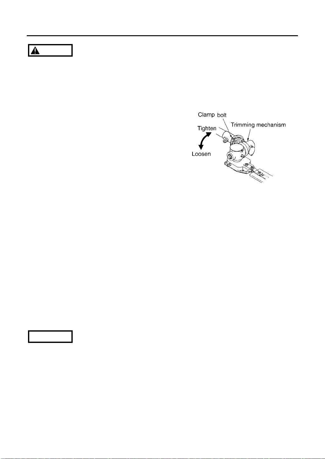
■Adjusting the angle of the cutting blades
1.Stop the trimmer engine.
2. Turn the bolt located on the top of the
trimming mechanism counter-clockwise
to loosen it.
3. Adjust the angle of the blades to the
desired angle, and then fix the bolt
firmly back into place.
❲12❳
WARNING
Page 15

■Be sure to check the following before using your trimmer.
Item to be checked Response
1
Trimming mechanism
• See if attachment is loose • Tighten screws and bolts
• Gaps between blades • Adjust blades (see p.14)
•
Check if edges of blades are dull
• Sharpen or replace blades
2 Throttle • Stiff and difficult to move • Repair or replace
3 Throttle wire • Too loose, too tight • Adjust (see p.11)
• Stiff and difficult to move • Repair or replace
4 Engine attachment •See if fittings are loose • Tighten fittings
5 Fuel tank • See if attachment is loose • Tighten screws and bolts
• See if fuel pipe is damaged • Replace
•
See if cap packing is damaged
• Replace
6 Muffler • See if attachment is loose • Tighten screws and bolts
■Regular maintenance inspection
Check the trimmer for damage or problems at the intervals shown below.
Maintenance
•Always be sure to stop the engine before inspecting the trimmer for problems or
performing maintenance.
•Never alter the trimmer or take the engine apart.
•When replacing parts, always be sure to use only ZENOAH products or products which
have been certified by ZENOAH for use with the RedMax trimmer.
•Things to check before using trimmer
WARNING
Interval (number of hours)
Item to be checked 20 25 50 100 Comments
Engine
Remove grit from cylinder fins √
Clean air filter element √
Clean and adjust spark plugs √ distance of 0.25"
Clean fuel tank √
Tighten cylinder bolts √
Tighten engine fittings √
Decarbonize muffler √
Main body
Lubricate gear case √
Remove grit from clutch drums √
❲13❳
Page 16

❲14❳
Maintenance
■BLADES
•When refilling the tank or resting, it is often
a good idea to use the time to oil the
cutting blades.
•If a gap exists between the upper and lower
blades, follow the procedure below to
adjust them so that they fit more closely
together.
1. Loosen lock nut (A) as shown in the
diagram.
2. Tighten screw (B) fully, and then turn
one-third to one-half of a rotation
backward.
3. While holding onto the screw to keep it
in position, tighten the lock nut.
4.Check to make sure that the flat washer
(C) is loose enough so that it may be
turned by pressing on it with a finger.
Screwing in the screw too tightly may make
it impossible for the blades to move.
Conversely, not screwing in the screw tightly
enough may make the blades of the trimmer
feel dull and cause leaves and branches to
become caught in the blades of the trimmer.
QUICK TIP
If the blades become so worn down that it is
no longer possible to eliminate the gap
between them, you should contact the
authorized RedMax servicing dealer from
which you purchased your RedMax®
trimmer to have the blades resharpened or
replaced.
NOTE
■GEAR CASE
The inside of the gear case should be
lubricant using ZENOAH-approved lubricant
after every 20 hours of use.
When adding lubricant, use a grease gun to
insert lubricant into the three grease nipples
located on the gear case.
TYPE OF LUBRICANT TO BE USED
Always be sure to use #2 lithium
heat-resistant lubricant.
Page 17

■FUEL FILTER
• A clogged fuel filter may cause poor
acceleration of the engine. Check
periodically to see if the filter is clogged
with dirt. The filter can be taken out of the
fueling port using a small wire hook.
Disconnect the filter assembly from the fuel
pipe and unhook the retainer to
disassemble it. Clean the components with
gasoline.
■SPARK PLUG
•The spark plug may gather carbon deposits
on its firing end with reasonable use.
Remove and inspect the spark plug every
25 hours and clean the electrodes as
necessary with a wire brush. The spark gap
should be adjusted to .025 in.
• Plug manufacturers recommend replacing
the plug twice a year to avoid unexpected
plug failure in a job.
REPLACEMENT PLUG IS A CHAMPION
RCJ6Y OR THE EQUIVALENT, SUCH AS
BOSCH WR8E OR NGK BR6S.
•Note that using any spark plugs other than
those designated may result in the engine
failing to operate properly or in the engine
becoming overheated and damaged.
• To install the spark plug, first turn the plug
until it is finger tight, then tighten it a
quarter turn more with a socket wrench.
IMPORTANT
• Make sure that the engine has stopped
and is cool before performing any
service to the trimmer. Contact with
moving cutting head or hot muffler may
result in a personal injury.
■AIR CLEANER
• C h e c k the air cleaner every 25 hours of
use or more frequently if used under dusty
conditions. A clogged air filter may increase
fuel consumption while cutting down the
engine power. Never operate the trimmer
without the air filter or with a deformed filter
element because unfiltered dusty air will
quickly ruin the engine.
•CLEANING AIR FILTER:
1.Remove the air cleaner cover by pulling
the tab on bottom and take out the filter
element.
2. Use neutral detergent and warm water
to clean the filter element. After cleaning,
air dry the element completely and
moisten with a small amount of motor oil.
3. Place the filter element into the air
cleaner housing and press the cover
against the housing until it clicks.
WARNING
Maintenance
❲15❳
Page 18

❲16❳
Maintenance
■INTAKE AIR COOLING VENT
• Never touch the cylinder, muffler, or
spark plugs with your bare hands
immediately after stopping the engine.
The engine can become very hot when
in operation, and doing so could result
in severe burns.
• When checking the trimmer to make
sure that it is okay before using it,
check the area around the muffler and
remove any wood chips or leaves which
have attached themselves to the
trimmer. Note that failing to do so could
cause the muffler to become
overheated, and that this in turn could
cause the trimmer to catch on fire.
Always make sure that the muffler is
clean and free of wood chips, leaves,
and other waste before use.
Check the intake air cooling vent and the
area around the cylinder cooling fins after
every 25 hours of use for blockage, and
remove any waste which has attached itself
to the trimmer. Note that it is necessary to
remove the plug guard shown in Figure 20 in
order to be able to view the upper part of the
cylinder.
If waste gets stuck and causes blockage
around the intake air cooling vent or
between the cylinder fins, it may cause the
engine to overheat, and that in turn may
cause mechanical failure on the part of the
trimmer.
IMPORTANT
■ PROCEDURES TO BE PERFORMED
AFTER EVERY 100 HOURS OF USE
1. Remove the muffler, insert a screwdriver
into the vent, and wipe away any carbon
buildup. Wipe away any carbon buildup
on the muffler exhaust vent at the same
time.
2.Tighten all screws, bolts, and fittings.
3. Check to see if any oil or grease has
worked its way in between the clutch lining
and drum, and if it has wipe it away using
oil-free, lead-free gasoline.
WARNING
Page 19
Storage
BEFORE STORING THE TRIMMER
1.Drain a fuel tank and push the primer bulb
until it becomes empty of fuel.
2.Remove the spark plug and drop a
spoonful of 2-cycle oil into the cylinder.
Pull the starter rope several time and
replace the plug.
❲17❳
Maintenance
■MUFFLER
• Inspect periodically, the muffler for loose
fasteners, any damage or corrosion. If any
sign of exhaust leakage is found, do not
use the trimmer and have it repaired
immediately.
• Note that failing to do so may result in
the engine catching on fire.
WARNING
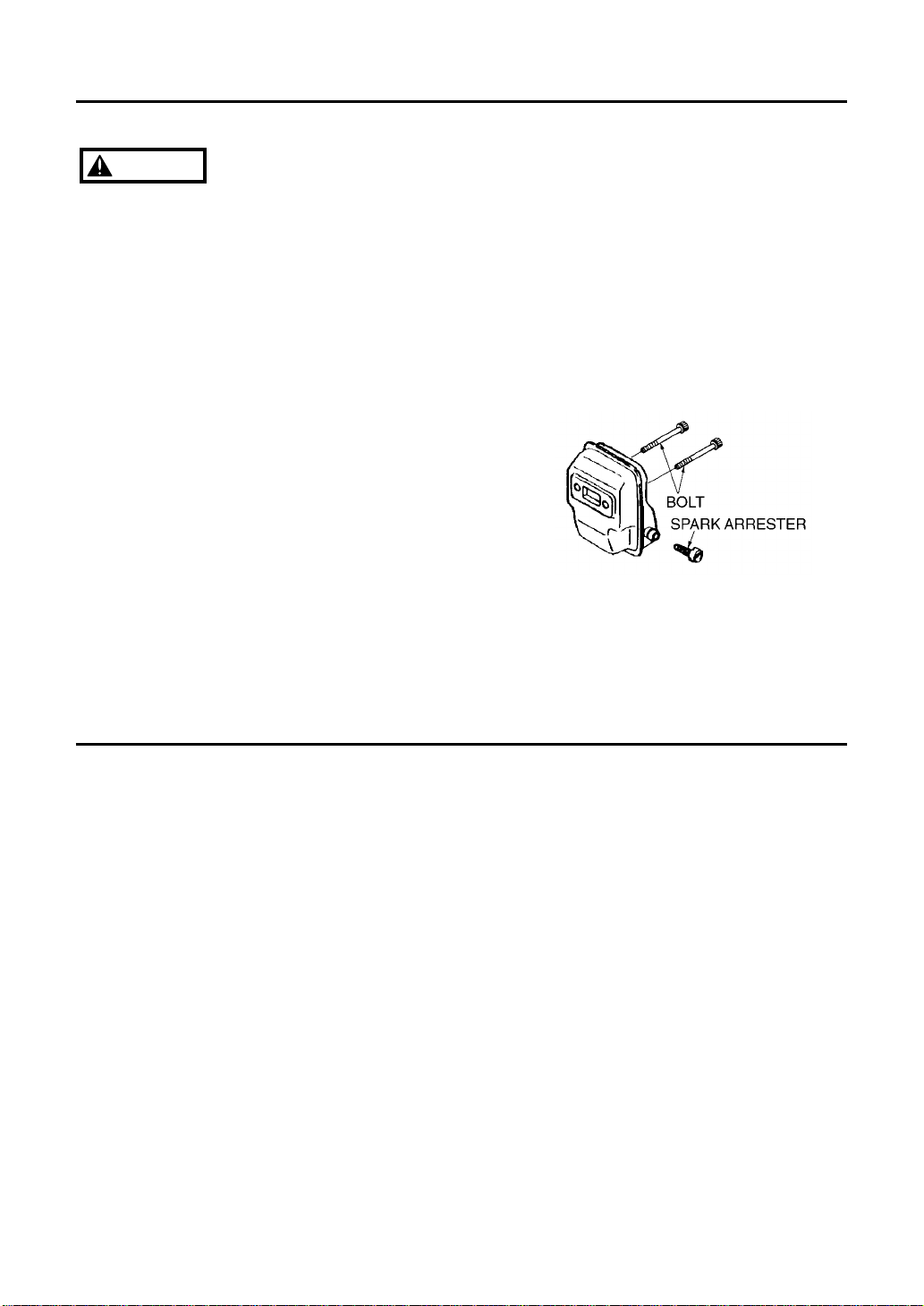
■SPARK ARRESTER
• The muffler is equipped with a spark
arrester to prevent red hot carbon from
flying out of the exhaust outlet. Periodically
inspect and clean as necessary with a wire
brush. In the State of California it is
required by law (Section 4442 of the
California Public Resources Code) to equip
a spark arrester when a gas powered tool
is used in any forest covered, brush
covered, or grass covered unimproved
land.
Page 20

Parts List : LRT2300
❲18❳
Fig.1 TRIMMER GROUP
Page 21

LRT2300
Fig.1 TRIMMER GROUP
Key# Description Part Number Q'ty
1 HOUSING, ASS’Y 6460-11002 1
2 CUSHION 6470-31230 1
3 BRACKET (A) 6460-31210 1
4 BRACKET (B) 6460-31220 1
5 BOLT 01252-30514 1
6 BOLT 01252-30530 2
7 DRUM, clutch 6460-12111 1
8 SNAP, ring 04065-02812 1
9 BEARING 06004-06001 1
10 SNAP, ring 04064-01210 1
11 BOLT 6468-91150 4
12 HANGER comp. 6460-17100 1
13 HANGER 9366-17110 1
14 CLAMP 6460-17120 1
15 SCREW 0263-90525 1
16 LEVER ASS'Y 181124 1
17 THROTTLE lever 180975 1
18 SCREW 145569 1
19 SCREW 180974 4
20 SPRING 610314 1
21 STOP switch 180252 1
22 CORD, red 180768 1
23 CORD, black 180769 1
24 CABLE COMP. 1
25 BOLT M6x20 6872-13110 1
26 WASHER M6 0290-20615 1
27 WASHER 6x6x2.0 6598-13130 1
28 ANGLE ADJUSTER 6782-13140 1
29 BOLT M6x12 0225-10612 2
30 CASING 6782-13210 1
31 GREESE FITTING 3199-13350 3
32 LABEL 6782-13250 1
33 SCREW M4x8 0263-10408 2
34 COVER 6598-13320 1
35 SNAP RING 6598-13330 1
36 BEVEL GEAR 6782-13340 1
37 SNAP RING 04065-02612 1
38 BEARING 06004-06000 1
39 CRANK SHAFT 6782-13370 1
40 SNAP RING 04064-02815 1
41 BLADE 6782-13410 2
42 BEARING 6782-13430 1
43 COVER 6782-13440 1
44 BOLT M4x8 0225-10408 4
45 FELT 6782-13460 2
46 SCREW 3884-11750 1
47 WASHER 3880-11780 4
48 SCREW 6598-13510 3
49 SCREW M5x20 6598-13530 2
50 GUIDE PLATE 6782-13540 1
51 PLATE 6782-13550 1
52 NUT M5 6782-14470 2
Key# Description Part Number Q'ty
53 NUT M6 3880-11790 4
54 SHAFT KIT T4008-06010 1
55 NUT M6 0280-10605 1
56 SHAFT N/A 1
57 GEAR(B) N/A 1
58 GEAR(C) T4008-13630 1
59 BOSS N/A 1
60 SPRING T4008-13650 1
61 PLATE T4008-13660 1
62 WASHER T4008-13670 1
63 WASHER T4008-13680 1
64 WASHER 6x15x2.0 6782-13650 1
65 BEARING 6598-13430 1
66 SNAP RING 04065-02212 1
67 O-RING 6598-13620 1
68 SNAP RING 04065-02612 1
69 BEARING 06004-06000 1
70 CASING B 6782-13710 1
71 WASHER 6x16x2.0 6598-13130 1
72 BOLT M6x12 0225-10612 1
73 WASHER 6782-13720 1
74 SCREW M5x10 0263-00510 1
75 BOLT M5x25 0225-10525 1
76 WASHER M5 0291-20510 1
77 JOINT 6782-13810 1
78 GEAR SHAFT B 6598-13820 1
79 BEARING 6782-13830 2
80 SNAP RING 04065-02212 1
81 BEVEL GEAR 6782-13850 1
82 SNAP RING 6598-13330 1
83 PACKING 6598-13860 1
84 COVER 6598-13870 1
85 SCREW M4x8 0263-10408 2
86 BLADE COVER 6782-13910 1
87 HANDLE ASS'Y 6462-14100 1
88 HANDLE 6462-14310 1
89 CLAMP 6462-14320 1
90 SCREW M5x35 0263-90535 4
91 GOGGLE 180773 1
92 STRAP ASS'Y 160197 1
93 TOOL KIT 3550-91000 1
94 SCREWDRIVER 1030-91340 1
95 SOCKET 3239-91310 1
96 WRENCH 09007-00425 1
97 BAR 3540-91110 1
98 SPANNER 3540-91120 1
99 GRIP 180770 1
100 PIPE comp. 180771BC 1
101 SHAFT 3520-12212 1
102 DECAL 1
❲19❳
Page 22

Fig.2 ENGINE GROUP
❲
20
❳
Parts List : LRT2300
Page 23

LRT2300
❲21❳
Fig.2 ENGINE GROUP
Key# Description Part Number Q'ty
1 CYLINDER 5580-12110 1
2 GASKET, base 5500-12212 1
3 BOLT 1850-12130 2
4 INSULATOR 5500-13162 1
5 GASKET, insulator 5500-13121 1
6 GASKET, carburetor 5500-13131 1
7 SCREW 0263-90520 2
8 MUFFLER ASS'Y 5850-15100 1
9 ————— ————— —
10 ARRESTER 1601-15120 1
11 BOLT 01252-30550 2
12 GASKET, muffler 5910-15211 1
13 PLATE, muffler 5500-15220 1
14 SCREW 0263-90416 1
15 CRANKCASE COMP. 5500-21100 1
16 GASKET, case 5500-21141 1
17 BEARING 06030-06001 2
18 OIL SEAL 2169-21210 1
19 OIL SEAL 1850-21220 1
20 SNAP RING 04065-02812 1
21 SCREW 01252-30530 4
22 PISTON 5600-41111 1
23 RING 1100-41210 2
24 PIN 1101-41310 1
25 SNAP RING 1260-41320 2
26 BEARING 1140-41330 1
27 WASHER 1101-41340 2
28 CRANKSHAFT COMP. 5500-42001 1
29 NUT 1650-43230 1
30 KEY 1000-43240 1
31 SHOE, clutch 1140-51111 2
32 SCREW 1140-51250 2
33 SPRING 1970-51221 1
34 WASHER 1140-51230 2
35 WASHER 1970-51241 2
36 ROTOR 5501-71110 1
37 COIL ASS'Y 5501-71201 1
38 CORD 5500-71220 1
39 CAP 2616-71320 1
40 CAP, plug 1900-72111 1
41 SPRING 1900-72120 1
42 GROMMET 5500-72130 1
43 SPACER 1260-71261 2
44 BOLT 3310-72150 2
45 RECOIL ASS'Y 5500-75100 1
46 CASE COMP. 5500-75110 1
47 REEL 1850-75120 1
48 SPRING, spiral 1850-75130 1
49 SCREW 1850-75151 1
50 ROPE 1850-75160 1
51 KNOB 1140-75320 1
52 PLATE, stopper 5500-75170 1
53 PULLEY ASS'Y 1850-75201 1
54 RATCHET 1850-75221 1
55 SPRING 1850-75230 1
56 SCREW 0263-90416 4
57 CARBURETOR ASS'Y 5501-81000 1
Key# Description Part Number Q'ty
58 SCREW 1752-81110 2
59 BRACKET 5500-81120 1
60 RING 1751-81130 1
61 SWIVEL 1881-81140 1
62 VALVE ASS'Y ————— 1
63 SCREW, adjuster 1918-81170 1
64 NUT, adjuster 1751-81180 1
65 RING 1881-81130 1
66 O-RING 1751-81240 1
67 JET 5500-81251 1
68 DIAPHRAGM 3310-81260 1
69 GASKET, pump 1065-81410 1
70 DIAPHRAGM, pump 1065-81420 1
71 BODY, pump 1850-81450 1
72 SCREEN 3306-81380 1
73 GASKET, diaphragm 1850-81470 1
74 BODY, purge 1850-81490 1
75 PUMP, priming 1751-81510 1
76 COVER, pump 1850-81520 1
77 SCREW 1850-81530 4
78 SCREW 0263-90560 2
79 BODY ASS'Y 5500-82102 1
80 ————— ————— —
81 SLEEVE 1970-82190 2
82 PLATE, choke 5500-82131 1
83 LEVER, choke 5500-82140 1
84 SCREW 2630-33610 1
85 ELEMENT 5500-82171 1
86 COVER ASS'Y 5600-82202 1
87 KNOB 5500-82221 1
88 RING 5500-82230 1
89 COVER, fan 5501-31111 1
90 SCREW 0263-90520 4
91 COVER, engine 5580-32112 1
92 SCREW 1850-32160 1
93 SCREW 1900-31410 2
94 GUARD, plug 5500-32210 1
95 SCREW 0263-90514 1
96 SPARK PLUG 5602-73110 1
97 GROMMET 1852-72121 1
98 CORD COMP. 5501-73201 1
99 TANK ASS'Y 5500-85004 1
100 CAP ASS'Y 5601-85200 1
101 PACKING 5500-85220 1
102 HOLDER 5601-85230 1
103 CAP, holder 5600-85240 1
104 VALVE 5600-85250 1
105 PIPE COMP. 5500-85300 1
106 FILTER ASS'Y 5500-85400 1
107 CLIP 1260-85460 1
108 SCREW 5500-85510 3
109 CLIP 1950-86120 1
110 LABEL, recoil 5550-91120 1
111 ————— ————— —
Page 24

THE CALIFORNIA AIR RESOURCES BOARD AND KOMATSU ZENOAH Co. ARE PLEASED TO
EXPLAIN THE EMISSION CONTROL SYSTEM WARRANTY ON YOUR 1995 AND LATER LAWN AND
GARDEN EQUIPMENT ENGINE. IN CALIFORNIA, NEW UTILITY AND LAWN AND GARDEN
EQUIPMENT ENGINES MUST BE DESIGNED, BUILT AND EQUIPPED TO MEET THE STATE'S
STRINGENT ANTI-SMOG STANDARDS.
KOMATSU ZENOAH Co, MUST WARRANT THE EMISSION CONTROL SYSTEM ON YOUR LAWN AND
GARDEN EQUIPMENT ENGINE FOR THE PERIODS OF TIME LISTED BELOW PROVIDED THERE HAS
BEEN NO ABUSE, NEGLECT OR IMPROPER MAINTENANCE OF YOUR LAWN AND GARDEN
EQUIPMENT ENGINE.
YOUR EMISSION CONTROL SYSTEM. MAY INCLUDE PARTS SUCH AS THE CARBURETOR, THE
IGNITION SYSTEM, AND CATALYTIC CONVERTER. ALSO INCLUDED MAY BE THE HOSES, BELTS,
CONNECTORS AND OTHER EMISSION-RELATED ASSEMBLIES.
WHERE A WARRANTABLE CONDITION EXISTS, KOMATSU ZENOAH Co. WILL REPAIR YOUR LAWN
AND GARDEN EQUIPMENT ENGINE AT NO COST TO YOU INCLUDING DIAGNOSIS, PARTS AND
LABOR.
MANUFACTURER'S WARRANTY COVERAGE:
THE 1995 AND LATER UTILITY AND LAWN AND GARDEN EQUIPMENT ENGINES ARE
WARRANTED FOR TWO YEARS. IF ANY EMISSION-RELATED PART ON YOUR ENGINE IS
DEFECTIVE, THE PART WILL BE REPAIRED OR REPLACED BY KOMATSU ZENOAH Co.
OWNER'S WARRANTY RESPONSIBILITIES:
—AS THE LAWN AND GARDEN EQUIPMENT ENGINE OWNER, YOU ARE RESPONSIBLE FOR
THE PERFORMANCE OF THE REQUIRED MAINTENANCE LISTED IN YOUR OWNER'S
MANUAL. KOMATSU ZENOAH Co. RECOMMENDS THAT YOU RETAIN ALL RECEIPTS
COVERING MAINTENANCE ON YOUR LAWN AND GARDEN ENGINE, BUT KOMATSU
ZENOAH Co. CAN NOT DENY WARRANTY SOLELY FOR THE LACK OF RECEIPTS OR FOR
YOUR FAILURE TO ENSURE THE PERFORMANCE OF ALL SCHEDULED MAINTENANCE.
—AS THE LAWN AND GARDEN EQUIPMENT ENGINE OWNER, YOU SHOULD BE AWARE,
HOWEVER, THAT KOMATSU ZENOAH Co. MAY DENY YOU WARRANTY COVERAGE IF
YOUR LAWN AND GARDEN EQUIPMENT ENGINE OR A PART HAS FAILED DUE TO ABUSE,
NEGLECT, IMPROPER MAINTENANCE OR UNAPPROVED MODIFICATION.
—YOU ARE RESPONSIBLE FOR PRESENTING YOUR LAWN AND GARDEN EQUIPMENT
ENGINE TO A KOMATSU ZENOAH Co. DISTRIBUTION CENTER AS SOON AS A PROBLEM
EXISTS. THE WARRANTY REPAIRS SHOULD BE COMPLETED IN A REASONABLE AMOUNT
OF TIME, NOT TO EXCEED 30 DAYS.
IF YOU HAVE ANY QUESTIONS REGARDING YOU WARRANTY RIGHTS AND RESPONSIBILITIES,
YOU SHOULD CONTACT KOMATSU ZENOAH AMERICA INC. AT (770)-381-5147.
CALIFORNIA EMISSION CONTROL WARRANTY STATEMENT
YOUR WARRANTY RIGHTS AND OBLIGATIONS
Page 25

EMISSION-RELATED PARTS, FOR TWO (2) YEARS FROM THE DATE OF ORIGINAL DELIVERY OF THE MODEL
LRT2300 UNIT, KOMATSU ZENOAH AMERICA INC. (THE COMPANY), THROUGH ANY RedMax DEALER, WILL REPAIR
OR REPLACE, FREE OF CHARGE, FOR THE ORIGINAL AND EACH SUBSEQUENT PURCHASER, ANY PART OR
PARTS FOUND TO BE DEFECTIVE IN MATERIAL AND/OR WORKMANSHIP. EMISSION-RELATED PARTS ARE:
THE CARBURETOR ASSY, COIL ASSY, ROTOR, SPARK PLUG,
AIR FILTER, FUEL FILTER, INTAKE MANIFOLD, AND THE GASKETS
ALL OTHER PARTS EXCEPT ABOVE PARTS, FOR TWO (2) YEARS OF HOME USE [ ONE (1) YEAR FOR ANY OTHER
USE ] FROM THE DATE OF ORIGINAL ANY DELIVERY OF THE MODEL LRT2300 UNIT, THE COMPANY, THROUGH
ANY RedMax DEALER, WILL REPAIR OR REPLACE, FREE OF CHARGE, FOR THE ORIGINAL PUSHCHASER, ANY
PART OR PARTS FOUND TO BE DEFECTIVE IN MATERIAL AND/OR WORKMANSHIP. THIS IS THE EXCLUSIVE
REMEDY.
THE PURCHASER SHALL BEAR COSTS OF TRANSPORTING THE UNIT TO AND FROM THE RedMax DEALER.
THE PURCHASER SHALL NOT BE CHARGED FOR DIAGNOSTIC LABOR WHICH LEADS TO THE DETERMINATION
THAT A WARRANTED PART ID DEFECTIVE, IF THE DIAGNOSTIC WORK IS PERFORMED AT THE RedMax DEALER.
THE PURCHASER OR OWNER IS RESPONSIBLE FOR THE PERFORMANCE OF THE REQUIRED MAINTENANCE AS
DEFINED BY THE MANUFACTURER IN THE OWNER/OPERATOR MANUAL.
ANY WARRANTED PART WHICH IS NOT SCHEDULED FOR REPLACEMENT AS REQUIRED MAINTENANCE, OR
WHICH IS SCHEDULED ONLY FOR REGULAR INSPECTION TO THE EFFECT OF "REPAIR OR REPLACE AS
NECESSARY" SHALL BE WARRANTED FOR THE WARRANTY PERIOD. ANY WARRANTED PART WHICH IS
SCHEDULED FOR REPLACEMENT AS REQUIRED MAINTENANCE SHALL BE WARRANTED FOR THE PERIOD OF
TIME UP TO THE FIRST SCHEDULED REPLACEMENT POINT FOR THAT PART.
ANY REPLACEMENT PART THAT IS EQUIVALENT IN PERFORMANCE AND DURABILITY MAY BE USED IN NONWARRANTY MAINTENANCE OR REPAIRS, AND SHALL NOT REDUCE THE WARRANTY OBLIGATION OF THE
COMPANY.
THE COMPANY IS LIABLE FOR DAMAGES TO OTHER ENGINE COMPONENTS CAUSED BY THE FAILURE OF A
WARRANTED PARTS STILL UNDER WARRANTY.
THIS WARRANTY DOES NOT APPLY TO THOSE UNITS WHICH HAVE BEEN DAMAGED BY NEGLIGENCE OF
INSTRUCTION LISTED IN THE OWNER/OPERATOR MANUAL FOR PROPER USE AND MAINTENANCE OF THE UNITS,
ACCIDENT MISHANDLING, ALTERATION, ABUSE, IMPROPER LUBRICATION. USE OF ANY PARTS OR ACCESSORIES
OTHER THAN THOSE SPECIFIED BY THE COMPANY, OR OTHER CAUSES BEYOND THE COMPANY'S CONTROL.
THIS WARRANTY DOES NOT COVER THOSE PARTS REPLACED BY NORMAL WEAR OR HARMLESS CHANGES IN
THEIR APPEARANCE.
THERE ARE NO OTHER EXPRESS WARRANTIES.
IMPLIED WARRANTIES INCLUDING THOSE OF MERCHANTABILITY AND FITNESS FOR A PARTICULAR PURPOSE
ARE LIMITED TO TWO (2) YEARS OF HOME USE [ONE (1) YEAR FOR ANY OTHER USE] FROM THE ORIGINAL
DELIVERY DATE.
LIABILITIES FOR INCIDENTAL OR CONSEQUENTIAL DAMAGE UNDER ANY AND ALL WARRANTIES
ARE EXCLUDED.
SOME STATES DO NOT ALLOW LIMITATION ON HOW LONG AN IMPLIED WARRANTY LASTS OR EXCLUSION OR
LIMITATION OF INCIDENTAL OR CONSEQUENTIAL DAMAGES, SO THE ABOVE LIMITATION OR EXCLUSION MAY
NOT APPLY TO YOU.
THIS WARRANTY GIVES YOU SPECIFIC LEGAL RIGHTS, AND YOU MAY ALSO HAVE OTHER RIGHTS WHICH VARY
FROM STATE TO STATE.
IF YOU NEED TO OBTAIN INFORMATION ABOUT THE NEAREST SERVICE CENTER, PLEASE CALL KOMATSU
ZENOAH AMERICA INC. AT (770)-381-5147.
IMPORTANT: YOU WILL RECEIVE A WARRANTY REGISTRATION CARD AT TIME OF PURCHASE. PLEASE FILL
OUT THE CARD AND SEND IT TO RedMax / KOMATSU ZENOAH AMERICA WITHIN SEVEN (7) DAYS. BE SURE TO
KEEP A COPY FOR YOUR RECORDS.
RedMax LONG REACH TRIMMER
MODEL LRT2300
2-YEAR LIMITED WARRANTY
KOMATSU ZENOAH AMERICA INC.
1505 Pavilion Place Suite A
Norcross, Georgia 30093
Page 26

KOMATSU ZENOAH AMERICA INC.
1505 Pavilion Place Suite A
Norcross, Georgia 30093
 Loading...