

Page 1
Owner/ Operator Manual
WARNING
!
!
The engine exhaust from this product
contains chemicals known to the State
of California to cause cancer, birth
defects or other reproductive harm.
WARNING
!
!
Before using our products, please
read this manual carefully to
understand the proper use of
your unit.
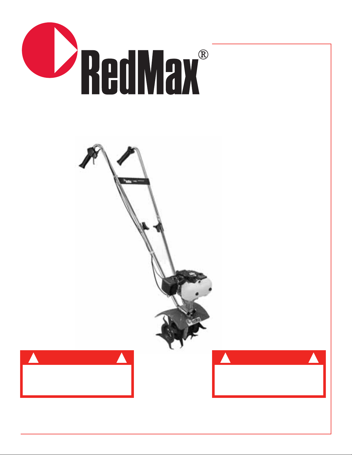
Tiller/Cultivator CV225
0706
Page 2

2
The REDMAX Tiller/Cultivator tills and weeds
precisely “to handle” your most difficult jobs. It
handles smoothly while the “bolo-tine” tines churn soil
to ten inches deep. It creates a soft smooth seed bed,
even in problem stony soil.
Once you know how to use your Precision
Tiller/Cultivator correctly, we guarantee you’ll love it.
So first, please read this manual. It shows, step by step,
how to use your Tiller/Cultivator safely.
If you have questions about any topic in this Manual
contact your local authorized REDMAX dealer.
Welcome to the World of REDMAX Ga rdening
Specifications . . . . . . . . . . . . . . . . . . . . . . . . . . . . . . . . . . . . . . . . . . . . . . . . . . . . . . . . . . . . . . . . . . . . . . . . .3
Safety Rules and Warnings . . . . . . . . . . . . . . . . . . . . . . . . . . . . . . . . . . . . . . . . . . . . . . . . . . . . . . . . . . . . . .4
Assembly Instructions . . . . . . . . . . . . . . . . . . . . . . . . . . . . . . . . . . . . . . . . . . . . . . . . . . . . . . . . . . . . . . . . . .8
Fuel Mix . . . . . . . . . . . . . . . . . . . . . . . . . . . . . . . . . . . . . . . . . . . . . . . . . . . . . . . . . . . . . . . . . . . . . . . . . . . .11
Starting Instructions . . . . . . . . . . . . . . . . . . . . . . . . . . . . . . . . . . . . . . . . . . . . . . . . . . . . . . . . . . . . . . . . . . .12
Additional Information . . . . . . . . . . . . . . . . . . . . . . . . . . . . . . . . . . . . . . . . . . . . . . . . . . . . . . . . . . . . . . . .13
What to do Just in Case . . . . . . . . . . . . . . . . . . . . . . . . . . . . . . . . . . . . . . . . . . . . . . . . . . . . . . . . . . . . . . . .14
Tilling . . . . . . . . . . . . . . . . . . . . . . . . . . . . . . . . . . . . . . . . . . . . . . . . . . . . . . . . . . . . . . . . . . . . . . . . . . . . . .15
Cultivating . . . . . . . . . . . . . . . . . . . . . . . . . . . . . . . . . . . . . . . . . . . . . . . . . . . . . . . . . . . . . . . . . . . . . . . . . .16
Maintenance . . . . . . . . . . . . . . . . . . . . . . . . . . . . . . . . . . . . . . . . . . . . . . . . . . . . . . . . . . . . . . . . . . . . . . . . .17
Storage . . . . . . . . . . . . . . . . . . . . . . . . . . . . . . . . . . . . . . . . . . . . . . . . . . . . . . . . . . . . . . . . . . . . . . . . . . . . .21
Troubleshooting Guide . . . . . . . . . . . . . . . . . . . . . . . . . . . . . . . . . . . . . . . . . . . . . . . . . . . . . . . . . . . . . . . .22
Parts List . . . . . . . . . . . . . . . . . . . . . . . . . . . . . . . . . . . . . . . . . . . . . . . . . . . . . . . . . . . . . . . . . . . . . . . . . . .23
Cultivator Assembly . . . . . . . . . . . . . . . . . . . . . . . . . . . . . . . . . . . . . . . . . . . . . . . . . . . . . . . . . . . . . . . . . . .24
Engine Assembly . . . . . . . . . . . . . . . . . . . . . . . . . . . . . . . . . . . . . . . . . . . . . . . . . . . . . . . . . . . . . . . . . . . . .26
Warranty . . . . . . . . . . . . . . . . . . . . . . . . . . . . . . . . . . . . . . . . . . . . . . . . . . . . . . . . . . . . . . . . . . . . . . . . . . . .28
Emissions Statement . . . . . . . . . . . . . . . . . . . . . . . . . . . . . . . . . . . . . . . . . . . . . . . . . . . . . . . . . . . . . . . . . .30
Table of Contents
Page 3

3
Model . . . . . . . . . . . . . . . . . . . . . . . . . . . . . . . . . . . . . . . . . . . . . . . . . . . . . . . . . . . . . . . . . . . . . . . . .CV225
Overall Size (L x W x H) . . . . . . . . . . . . . . . . . . . . . . . . . . . . . . . .47 (1194) x 11 (280) x 38 (965) in (mm)
Dry weight w/o acc. . . . . . . . . . . . . . . . . . . . . . . . . . . . . . . . . . . . . . . . . . . . . . . . . . . . . . . . . . . .21.5 LBS (9.8kg)
Engine Type . . . . . . . . . . . . . . . . . . . . . . . . . . . . . . . . . . . . . . . . . . . . . . . . . . . .Air cooled 2-stroke gasoline
Model . . . . . . . . . . . . . . . . . . . . . . . . . . . . . . . . . . . . . . . . . . . . . . . . . . . . . . . . . . . . . . . . . . . .Zenoah
Displacement . . . . . . . . . . . . . . . . . . . . . . . . . . . . . . . . . . . . . . . . . . . . . . . . . . . . .1.4cu-in (22.5cm3)
Max. Output . . . . . . . . . . . . . . . . . . . . . . . . . . . . . . . . . . . . . . . . . . . . . . . . . . . . .1.08Hp at 8000rpm
Fuel . . . . . . . . . . . . . . . . . . . . . . . . . . . . . . . . . . . . . . . . . . . . . . . . . . . .Mixture (Gasoline 50 : Oil1)
Carburetor . . . . . . . . . . . . . . . . . . . . . . . . . . . . . . . . . . . . . . . . . . . . . . . . . . .Walbro Diaphragm type
Spark plug . . . . . . . . . . . . . . . . . . . . . . . . . . . . . . . . . . . . . . . . . . . . . . . . . . . . . . .Champion RCJ6Y
Fuel tank capacity . . . . . . . . . . . . . . . . . . . . . . . . . . . . . . . . . . . . . . . . . . . . . . . . . . . . . . . .20.3 fl.. oz (0.6L)
Transmission . . . . . . . . . . . . . . . . . . . . . . . . . . . . . . . . . . . . . . . . . . . . . .Centrifugal clutch, Rigid driveshaft
Reduction ratio . . . . . . . . . . . . . . . . . . . . . . . . . . . . . . . . . . . . . . . . . . . . . . . . . . . . . . . . . . . . . . . . . . . . .42:1
Durability period . . . . . . . . . . . . . . . . . . . . . . . . . . . . . . . . . . . . . . . . . . . . . . . . . . . . . . . . . . . . . . . . .150 hrs.
Specifications are subject to change without notice.
Specifications
Page 4
4
You will notice throughout this Owners Manual
Safety Rules and Important Notes. Make sure you
understand and obey these warnings for your own
protection.
Special Safety Information
Safety and Warnings
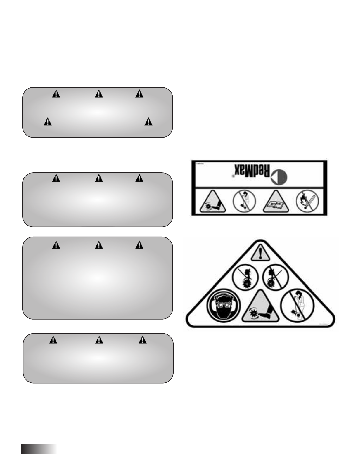
Safety Decal Information
An important part of the safety system incorporated
in this trimmer are the warning and information
decals found on various parts of the trimmer. These
decals must be replaced in time due to abrasion, etc.
It is your responsibility to replace the decals when
they become hard to read. The location of these
decals and their part numbers for ordering are shown
below.
Safety Rules and Warnings
WARNING DANGER
ATTENTION: THIS SYMBOL POINTS OUT OUR
IMPORTANT SAFETY INSTRUCTIONS
WHEN YOU SEE THIS SYMBOL
HEED ITS WARNING! STAY ALERT!
WARNING DANGER
TO REDUCE THE POTENTIAL FOR ACCIDENTS,
COMPLY WITH THE SAFETY INSTRUCTIONS IN
THIS MANUAL. FAILURE TO COMPLY MAY
RESULT IN SERIOUS PERSONAL INJURY AND OR
EQUIPMENT AND PROPERTY DAMAGE.
WARNING DANGER
IMPROPER USE OR CARE OF THIS
TILLER/CULTIVATOR, OR FAILURE TO WEAR
PROPER PROTECTION CAN RESULT IN
SERIOUS INJURY.
READ AND UNDERSTAND THE RULES FOR SAFE
OPERATION AND ALL INSTRUCTIONS
IN THIS MANUAL.WEAR HEARING PROTECTION.
WARNING DANGER
THE ENGINE EXHAUST FROM THIS PRODUCT
CONTAINS CHEMICALS KNOWN TO THE STATE
OF CALIFORNIA TO CAUSE CANCER, BIRTH
DEFECTS OR OTHER REPRODUCTIVE HARM.
Page 5

WEAR EAR AND EYE
PROTECTION.
CUTTING HAZARD; KEEP
FEET AND HANDS AWAY
FROM ROTATING TINES.
DO NOT CARRY THE
TILLER/CULTIVATOR IN
THIS POSITION.
READ OWNER’S MANUAL
BEFORE USING
TILLER/CULTIVATOR, OR
PERFORMING ANY REPAIR
OR MAINTENANCE. KEEP
OWNERS MANUAL IN A
SAFE PLACE.
DON’T FUEL, REFUEL, OR
CHECK FUEL WHILE
SMOKING, OR NEAR AN
OPEN FLAME OR OTHER
IGNITION SOURCE.
CAUTION: WHEN
ASSEMBLING THE
HANDLES, MAKE SURE
FUEL TANK FACES AWAY
FROM OPERATOR. THIS IS
THE REAR OF THE
TILLER/CULTIVATOR,
REFER TO ASSEMBLY
INSTRUCTION ON PAGE 8.
INCORRECT ASSEMBLY.
Safety Decal Information cont.
Warnings - Do’s
1. Always keep a firm grip on both handles while
the tines are moving and/or the engine is
running. BE AWARE!! The tines may coast after
throttle trigger is released. Make sure tines have
come to a complete stop and engine is off before
letting go of the Tiller/Cultivator.
2. Always maintain a firm footing and good
balance. Do not overreach while operating the
Tiller/Cultivator. Before you start to use the
Tiller/Cultivator, check the work area for
obstacles that might cause you to lose your
footing, balance or control of the machine.
3. Thoroughly inspect the area where equipment is
to be used and remove all objects, that can be
thrown by the machine.
WARNING DANGER
IF THE TILLER/CULTIVATOR PRECAUTIONS
ARE NOT FOLLOWED, THE USER RISKS
SERIOUS INJURY TO THEMSELVES
AND OTHERS.
READ AND UNDERSTAND THIS MANUAL
BEFORE ATTEMPTING TO OPERATE THIS
TILLER/CULTIVATOR.
5
Page 6
6
Warnings - Do’s cont.
4. Always keep area clear of children, pets, and
bystanders.
5. Always stay alert. Watch what you are doing and
use common sense. Do not operate unit when
fatigued.
6. Always dress properly. Do not wear loose
clothing or jewelry, they might get caught in
moving parts. Use sturdy gloves. Gloves reduce
the transmission of vibration to your hands.
Prolonged exposure to vibration can cause
numbness and other ailments.
7. While working, always wear substantial footwear
and long trousers. Do not operate the equipment
when barefoot or wearing open sandals.
8. Always wear ear and eye protection. Eye
protection must meet ANSI Z 87.1. To avoid
hearing damage, we recommend hearing
protection be worn whenever using the
equipment.
9. To reduce fire hazard, keep the engine, and
petrol/gas storage area free of vegetative material
and excessive grease.
10. Start the engine carefully, according to the
manufacturer’s instructions and with feet well
away from tool(s).
11. Keep all nuts, bolts and screws tight to be sure
the equipment is in safe working condition.
12. Use extreme caution when reversing or pulling
the machine towards you.
13. Work only in daylight or good artificial light.
14. Always be sure of your footing on slopes.
15. Exercise extreme caution when changing
direction on slopes.
16. Always keep a safe distance between two or
more people when working together.
17. Always inspect your unit before each use and
ensure that all handles, guards and fasteners are
secure, operating, and in place.
18. Always maintain and examine your
Tiller/Cultivator with care. Follow maintenance
instructions given in manual.
19. Always store Tiller/Cultivator in a sheltered area
(a dry place), not accessible to children. The
Tiller/Cultivator as well as fuel should not be
stored in a house.
Warnings - Don’ts
Don’t use Tiller/Cultivator with one hand. Keep both
hands on handles with fingers and thumbs encircling
the handles, while tines are moving, and engine is
running.
Don’t overreach. Keep a good footing at all times.
Don’t run with the machine, walk.
Don’t work on excessively steep slopes.
Don’t attempt to clear tines while they are moving.
Never try to remove jammed material before
switching the engine off and making sure the tines
have stopped completely.
Don’t allow children or incapable people to operate
this Tiller/Cultivator.
Don’t operate while under the influence of alcohol or
drugs.
Don’t attempt to repair this Tiller/Cultivator. Have
repairs made by a qualified dealer or repairman.
WARNING DANGER
FOR SAFE OPERATION AND MAINTENANCE,
SYMBOLS ARE CARVED IN RELIEF ON THE
MACHINE. ACCORDING TO THOSE INDICATIONS,
PLEASE BE CAREFUL NOT TO MAKE A MISTAKE.
THE PORT TO REFUEL THE “MIX GASOLINE”
POSITION: FUEL TANK CAP.
WARNING DANGER
IMPORTANT ENGINE INFORMATION
THIS ENGINE MEETS U.S. EPA PH1 AND 2001
CALIFORNIA EMISSION REGULATIONS FOR
SMALL OFF-ROAD ENGINES WITH AN EMISSION
DURABILITY PERIOD OF 300 HRS
ENGINE FAMILY : 1KZXS. 0254CD
ENGINE DISPLACEMENT : 22.5CC
REFER TO OWNER’S MANUAL FOR
MAINTENANCE SPECIFICATIONS
AND ADJUSTMENTS.
Page 7
Engine/ Fuel - Warnings - Do’s
Always use fresh gasoline. Stale gasoline can cause
damage.
Always store fuel in containers specifically designed
for this purpose.
Always pull starter cord slowly until resistance is felt.
Then pull cord rapidly to avoid kickback and prevent
arm or hand injury.
Always operate engine with spark arrestor installed
and operating properly. The use of spark arrestor
mufflers is required by law in the state of California
(Section 4442 of the California Public Resources
Code), as well as in other states or municipalities.
Federal laws apply on federal lands.
Stop the engine whenever you leave the machine.
Allow the engine to cool before storing in any
enclosure.
If the fuel tank needs to be drained, this should be
done outdoors.
Engine/ Fuel Warnings - Don’ts
Don’t fuel, refuel or check fuel while smoking, or
near an open flame or other ignition source. Stop
engine and be sure it is cool before refueling.
Don’t leave the engine running while the
Tiller/Cultivator is unattended. Stop engine before
putting the Tiller/Cultivator down or while
transporting from one place to another.
Don’t refuel, start or run this Tiller/Cultivator indoors
or in an improperly ventilated area.
Don’t run engine when electrical system causes spark
outside the cylinder. During periodic checks of the
spark plug, keep plug a safe distance from cylinder to
avoid burning of evaporated fuel from cylinder.
Don’t check for spark with spark plug or plug wire
removed. Use an approved tester.
Don’t crank engine with spark plug removed unless
spark plug wire is disconnected. Sparks can ignite
fumes.
Don’t run engine when the odor of gasoline is present
or other explosive conditions exist.
Don’t operate the unit if gasoline is spilled. Clean up
spill completely before starting engine.
Don’t operate your Tiller/Cultivator if there is an
accumulation of debris around the muffler, and
cooling fins.
Don’t touch hot mufflers, cylinders or cooling fins as
contact may cause serious burns.
Don’t change the engine governor setting or over
speed the engine.
7
WARNING DANGER
HANDLE FUEL WITH CARE, IT IS HIGHLY
FLAMMABLE. FUELING A HOT ENGINE OR NEAR
AN IGNITION SOURCE CAN CAUSE A FIRE AND
RESULT IN SERIOUS PERSONAL INJURY
AND/ OR PROPERTY DAMAGE.
WARNING DANGER
DO NOT MODIFY YOUR TILLER/CULTIVATOR .
WARRANTY WILL BE VOIDED IF YOU
USE THE REMODELED TILLER/CULTIVATOR
OR IF YOU DO NOT OBSERVE THE PROPER
USAGE WRITTEN IN THE MANUAL.
Page 8
8
Qty Description *Key #
1 Upper Handle 4
1 Upper Handle Throttle Side 5
2 Lower Handles 6
1 Pair Cultivator Tines 39/40
1 Engine Assembly
(includes Fender Guard
& Worm-Gear Transmission) 21, 20, 50
1 Handle Brace 8
1 Plastic Carrying Handle 42
Qty Description *Key #
1 Bag of Hardware Containing:
4 Cap Screws 52
6 Lock Nuts 53
2 Bolts (3 1/4" long) 54
2 Tine Retaining Pins 41
2 Transmission Bracket 47
1 Throttle Clip 13
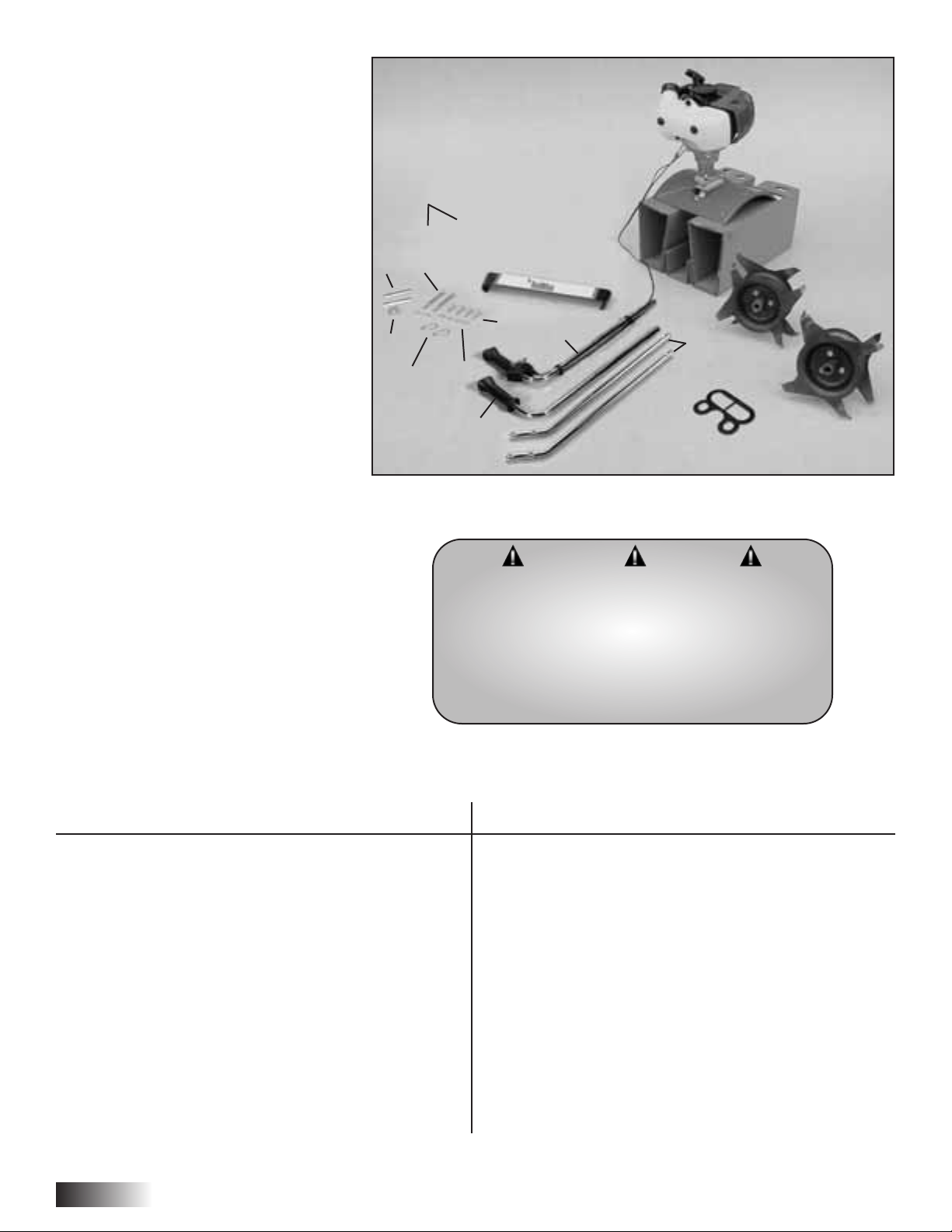
Your REDMAX Precision
Tiller/Cultivator comes partially
assembled. You must install only the
handlebars, the carrying handle, and
the tines. This will take just a few
minutes if you follow the directions.
First, take all items out of the
carton. But do not remove the
cardboard from around the
Tiller/Cultivator’s base.
The list below, shows the parts that
come with your Tiller/Cultivator.
Check to make sure you have them.
The bag of hardware is packed in the
plastic bag containing the owner’s
manual.
To assemble your REDMAX
Tiller/Cultivator, you’ll need two 7/16"
wrenches or two adjustable wrenches.
We suggest that you install all nuts and
bolts only “finger tight” — that is, onehalf to one full turn — until you’ve
completed assembly. The nuts are self
locking, but you must use a wrench
to tighten them completely.
Assembly Instructions
WARNING DANGER
IMPROPER ASSEMBLY OF THIS
TILLER/CULTIVATOR CAN RESULT IN
SERIOUS INJURY.
MAKE SURE TO FOLLOW ALL INSTRUCTIONS
CAREFULLY. IF YOU HAVE ANY QUESTIONS
CONTACT YOUR LOCAL REDMAX DEALER.
4
6
5
47
41
40
39
42
8
21
13
54
53
52
6
Page 9
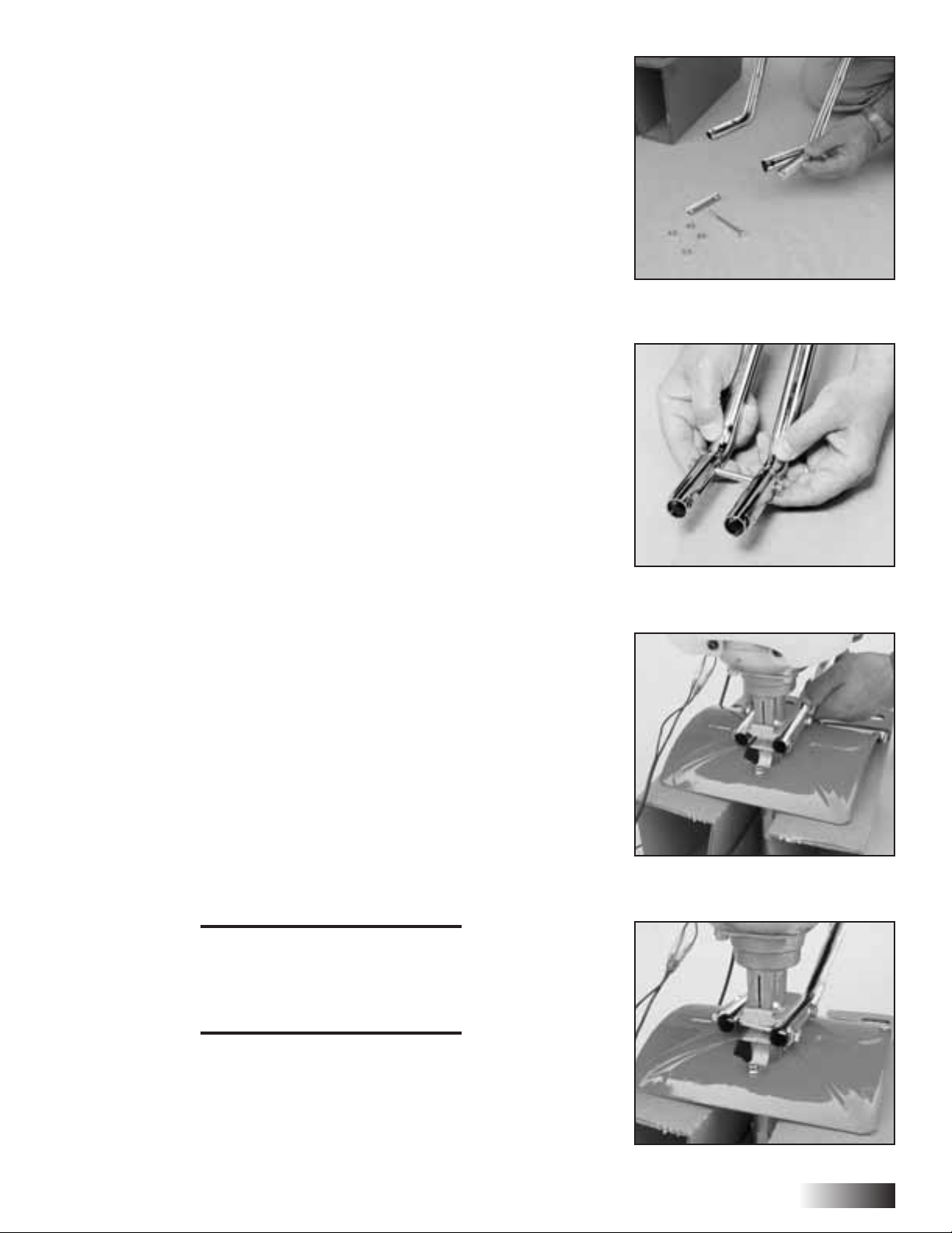
II. How to Assemble Lower Handles
To identify part numbers, see page 8.
1. Use the protective cardboard sleeve to stabilize your
Tiller/Cultivator. Stand the engine assembly up.
2. Lay the handle parts within easy reach. You’ll need the transmission
bracket (#47) and one of the lower handles (#6). Note that the lower
handles have a short leg on one end. (Picture 1)
3. Fit the transmission bracket along the outside of the short leg. Line
up the holes on the clamp and the leg.
4. Using one of the two 3 1/4" bolts (#54), slide it through the hole of
the transmission bracket (#47) and lower handle (#6) closest to the
elbow. (Picture 2) The fit will be tight.
5. Now slide the bolt completely through the second lower handle and
transmission bracket. (Picture 2) Add a nut (#53) and tighten finger
tight.
6. Locate the worm-gear housing. It starts just above — and extends
down through — the Tiller/Cultivator’s red fender. You’ll notice that
there’s a recessed channel on either side of the housing’s top.
7. Take the lower handles that you’ve just put together. Slide them into
the two recessed channels.
Make sure you insert them from the rear of the Tiller/Cultivator
(gasoline tank faces away from the operator) . . . so that the bolt fits
along the back of the housing.
8. Slide the second 3 1/4" bolt through the second hole in the short
legs. Add a nut (#53) and tighten finger tight. (Picture 4)
NOTE: THE NUTS ARE SELF
LOCKING, BUT YOU MUST
USE A WRENCH TO TIGHTEN
THEM COMPLETELY.
Picture 1
Picture 4
Picture 3
Picture 2
9
Page 10
Assembling the Tines for Tilling
1. Remove the cardboard from around your Tiller/Cultivator’s base.
2. Slide the tines onto the axle shafts. The “D” hole goes on the outside.
3. Make sure you’ve installed the tines properly for cultivating. Liken
the tines to your fingers. When your palm faces the ground, your
fingers curl down. Stand behind the Tiller/Cultivator and hold your
hand next to the tines. Do the tine blades curl down, as your fingers
do? If so, they are in the tilling position. (To switch to the cultivating
position, see page 16.)
4. To secure each tine to the axle,
insert a tine retaining pin.
IMPORTANT NOTE:
Before you use your REDMAX
Tiller/Cultivator, read the Safety
Rules & Warnings on pages 4-7.
Picture 5
Picture 4
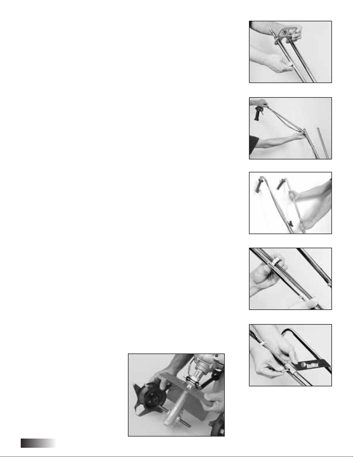
How to Assemble Upper Handles and Plastic Carrying Handle
1. Lightly squeeze the lower handles (#3) toward one another so that they line
up with the two smaller holes on the carrying handle (#29). Then slide the
carrying handle over and down the lower handles. It will rest about four to
six inches above the engine. (Picture 1)
2. Gently pull the lower handles out to their original position.
3. Attach the upper handle assembly (#1) – the handle with the throttle cable
and ground wire – onto the right handle, and secure with the handle knob
(#40) and 1 round head bolt (#39) (Picture 2). Be sure you have proper
throttle movements and that the throttle cable is not wrapped or twisted
around the handle bar. Squeeze trigger and let go. The triangle must click
in both directions. If there is any doubt, remove air filter and visually check
that the throttle triangle hits both the idle screw and the full open stop. THIS
MUST BE DONE BEFORE STARTING THE ENGINE.
4. Follow the same steps to install the left upper handle onto the other lower
handle. (Picture 3)
5. Use the clip (#6) to secure the throttle cable and wire in place on the lower
handle. (Picture 4)
6. Now install the Handle Brace. Line it up with the holes on the upper handles.
Then insert a Cap Screw (#34) and a Lock Nut (#35) on either side (Picture 5)
7. Use a wrench to tighten Cap Screws and Lock Nuts.
8. Now use wrench to tighten all nuts and bolts firmly and securely.
IMPORTANT NOTE:
Make sure you have installed the handles properly. When you stand behind
your Tiller/Cultivator, holding the handles, gasoline tank should be in front of
the unit.
Picture 1
Picture 2
Picture 3
10
Page 11

11
Your REDMAX Tiller/Cultivator is powered by a
commercial two stroke, air cooled engine which
requires a fuel mixture of gasoline and lubricating oil.
Use a mixture of 50 parts unleaded regular gasoline
and 1 part two-stroke oil (50:1.) Make sure to use
gasoline with a minimum octane number of 90 ROZ
(USA/Canada: pump octant Min. 87)
The REDMAX engines are lubricated by oil specially
formulated for air-cooled 2-cycle gasoline engine use.
If REDMAX oil is not available, use an anti-oxidant
added quality oil expressly labeled for air-cooled 2
cycle-engine use. (JASO FC GRADE OIL or ISO
EGC GRADE)
Recommended mixing ratio
Gasoline 50: Oil 1
Exhaust emission are controlled by the fundamental
engine parameters and components (eq., carburators,
ignition timing and port timing) without addition of
any major hardware or the introduction of an inert
material during combustion.
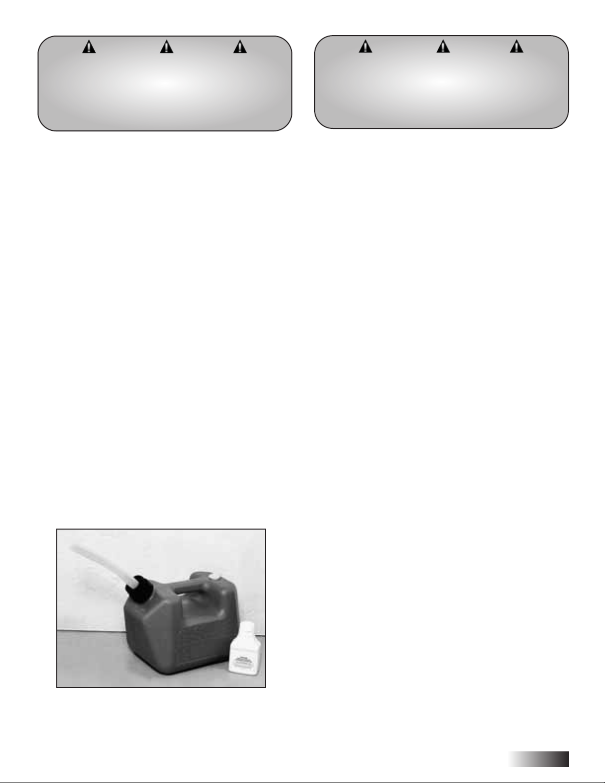
How to mix fuel:
1. Pour 1/2 of the gasoline into a safe container. Do
not mix the fuel and oil in the engine fuel tank.
2. Add 2.6 ounces (.077 liters) of two-cycle engine
oil to the gasoline and mix. Then add the rest of
the gasoline.
3. Screw the cap onto the gasoline can. Then swirl
the can to blend the oil and gas.
Fueling the unit:
1. Carefully pour the fuel mix into the `
Tiller/Cultivator’s fuel tank.
2. Put fuel into the fuel tank to 80% of the
full capacity.
3. Fasten the fuel cap securely and wipe up any fuel
spillage around the unit.
IMPORTANT: Two stroke fuel separates and ages.
Do not mix more than you will use in a month. Using
old fuel can cause difficult starting or engine damage.
Shake fuel container to thoroughly mix fuel before
each use. Do not attempt to run your engine on
gasoline only, use proper fuel mixture.
Need pre-measured engine oil? Contact your local
authorized REDMAX dealer.
Remember …
• Always mix two-cycle oil with gasoline before
fueling your Tiller/Cultivator. Never, ever run your
Tiller/Cultivator on gasoline alone. This will ruin
your engine and void all warranties.
• Always use a clean gas can and always use
unleaded gas.
• Never try to mix the oil and gasoline in the engine
fuel tank.
• Always mix oil and gas in the proper proportions:
2.6 ounces (.077 liters) of two-cycle engine oil to
one gallon (3.785 liters) of unleaded gasoline.
• Gasohol - It can cause deterioration of rubber
and/or plastic parts and disruption of
engine lubrication.
• Oil for 4-cycle engine use or water coded 2-cycle
engine use - it can cause spark plug fouling,
exhaust port blocking, or piston ring sticking.
IMPORTANT NOTE:
Do Not use old or stale oil/gasoline mixture.
Always use the proper oil/gasoline mixture. If you
do not, your engine will suffer rapid, permanent
damage. And you will void the engine warranty.
Fuel Mix
WARNING DANGER
FUEL IS EXTREMELY FLAMMABLE. HANDLE IT
WITH CARE. KEEP AWAY FROM IGNITION
SOURCES. DO NOT SMOKE WHILE FUELING
YOUR EQUIPMENT.
Gasoline liter 1234 5
2-cycle oil ml 20 40 60 80 100
Gasoline gal. 1234 5
2-cycle oil fl. oz 2.6 5.2 7.8 10.4 13
Page 12

Starting Your Tiller/Cultivator for the First Time
1. Fill the fuel tank with the proper oil/gasoline mixture.
(See previous section.)
2. Hand tighten the gasoline cap just until it’s snug.
3. Place the o/I switch into the I “start/on” position. (Picture 1)
4. Pull the choke button all the way out, to completely close the choke.
(Picture 2)
5. Locate the purge bulb on the upper right of the engine, in front of the
fuel tank. (See Picture 3) It sends fuel into the carburetor, for easy
starting. Press the purge bulb until you see fuel flow through the clear
fuel return line. Since you’re starting “cold,” you may need to press six
to eight times. As soon as fuel starts flowing through the clear fuel line,
stop pressing! (Picture 3)
6. Don’t press the throttle trigger during the starting of the engine.
7. Pull the starter cord (Picture 4) until resistance is felt. Then give the
recoil starter cord a few
brisk pulls until the engine fires. Note: Pull the
starter cord about 12" to 18".
During cold starting, you may need to pull
at least three or four times before the engine fires.
NOTE: When the choke is closed, never pull the cord more than four or
five times. Overpulling may cause flooding. Also, bear in mind that,
when the engine fires, it only coughs or sputters, and will not run on
choke.
8. Push the choke button in, all the way, to open the choke. (Picture 5)
9. Then pull the starter cord again. The engine should start and run. Let
the engine warm up two to three minutes before using.
Follow these steps whenever you are starting the engine “cold”, or
when the engine has run dry and you have just added fuel. Remember,
always use short, brisk pulls. Don’t give the cord a long, forceful yank.
And, do not let the cord snap back into the starter housing.
Starting Instructions
WARNING DANGER
NEVER USE STARTING FLUIDS AS THEY WILL
CAUSE PERMANENT ENGINE DAMAGE. USING
THEM WILL VOID THE WARRANTY.
BEFORE YOU USE THE TILLER/CULTIVATOR,
READ THE SAFETY WARNING
RULES ON PAGES 4-7.
Picture 1
Picture 5
Picture 4
Picture 3
Picture 2
12
Page 13

13
Starting a Warm Engine
1. Slide ignition switch to START position.
2. Move the choke lever to the Open (Run) position.
3. If there is no fuel in the clear return line, push
primer bulb 3-4 times or until fuel is visible in the
line.
4. Pull starter rope using short pulls, 1/2 to 2/3 of the
rope length.
5. If engine fails to start in 4 pulls, use “First Time”
starting procedure on page 14.
6. With engine running, and both hands on the
handles, squeeze throttle trigger gradually to
increase the engine speed and engage the tines.
Additional Information
How to Stop the Engine
Simply push the o/
I switch into the I “stop”
position. This will stop the engine instantly. If it
should ever fail to do so, just pull out the choke
button. The engine will stop at once.
About the Choke
The choke controls the amount of air drawn into the
engine. Your Tiller/Cultivator will run only if the
choke is open — that is, if the choke is pushed in.
A Special Feature (with the idle set properly and
the engine running)
Even when the engine is running, the tines won’t
turn unless you press the throttle lever on the
handlebars. And, when you release the throttle lever,
the tines will stop.
A Tip for Extending Your Engine’s Life
After you start the engine, let your Tiller/Cultivator
warm up for two to three minutes before you use it.
Then, before you put your Tiller/Cultivator away, let
it idle for a minute to give the engine a chance to
cool down.
WARNING DANGER
AVOID ACCIDENTAL BLADE ENGAGEMENT.
DO NOT SQUEEZE THE THROTTLE TRIGGER WHEN
STARTING. MAINTAIN PROPER IDLE
SPEED ADJUSTMENT (220 - 2300 RPM).
WARNING DANGER
IF ENGINE DOES NOT STOP WHEN SWITCH IS
PUT IN THE STOP POSITION, RELEASE THE
THROTTLE. ALLOW ENGINE TO IDLE.
PUT THE TILLER/CULTIVATOR DOWN, AND
PULL THE CHOKE BUTTON OUT TO COLD
START (CLOSED) POSITION.
CHECK AND RETURN IGNITION SWITCH TO ON
POSITION BEFORE STARTING ENGINE AGAIN.
Page 14

What to do Just in Case
If you follow the normal starting procedure, you
should have no problem starting your
Tiller/Cultivator. But, just in case you do have
problems, here’s what to do.
Make sure the start/stop switch is on “start.” You’d be
surprised how many people forget to push the switch
into the “start” position.
If the switch was on “stop” when you pulled the cord,
you may have flooded the engine.
• First, examine the spark plug. Use a 3/4" (19 mm)
inch spark plug wrench.
• Remove the cap over the spark plug. (Picture 1)
IMPORTANT NOTE:
To avoid possible damage to the threads, do not try
to remove the plug from a hot aluminum cylinder
head.
• Unscrew the spark plug. (Picture 2)
Starting a Flooded Engine
1. If the end of the spark plug is wet, the engine may
be flooded. Make sure the switch is in the stop
position, disconnect spark plug wire and
remove plug. Use a paper towel or a clean rag
to dry the spark plug, then, with the spark
plug out of the engine, pull the starter cord
several times. Shake the fuel out of the inside of
the plug and air dry. Next, replace the spark
plug. Use the wrench to tighten it and replace the
cap. Next, put the switch in the start position and
pull the choke button out. Pull the starter cord
three or four times until the engine coughs or
sputters. Open the choke (push the choke button
in) and pull the cord a few times. The engine
should start and run.
2. If the end of the spark plug is dry, check to see if
the fuel line is blocked. The fuel line runs from
the fuel tank to the carburetor. Pull it off at the
carburetor end. Fuel should drip slowly from the
line. Wipe off any excess or spilled fuel.
If fuel does not drip from the line, check the line
for any bends or pinches. (Picture 3) Kinks in the
line restrict the flow of fuel to the engine. Just
straighten out the line. Reconnect. Then follow
the normal starting procedure.
If fuel drips too freely, the line may be
disconnected from the fuel filter. You’ll find the
fuel filter inside the fuel tank. Just re-attach the
line to the filter, and put the filter back in the tank.
Then follow the normal starting procedure.
WARNING DANGER
MAKE SURE THE START/STOP SWITCH IS
IN THE STOP POSITION.
KEEP PLUG WIRE AWAY FROM ENGINE TO
AVOID UNINTENTIONAL SPARK.
Picture 1 Picture 2
14
Page 15

15
What to do Just in Case cont.
Here’s Another Way to Start your REDMAX
Tiller/Cultivator
If you follow the steps above and your engine still
won’t start, try this:
1. Push the switch to “start.”
2. Move the choke lever to open the choke.
3. Press the plastic bubble a few times.
4. Give the starter cord a few short, quick pulls. The
engine should start and run.
5. If the engine does not start, then move the choke
lever to close the choke. Pull the starter cord four
to five times. The engine should sputter or cough.
6. After the engine sputters, push the choke button in.
Then pull the starter cord. The engine should start
and run.
7. If the engine still does not start, repeat steps 2
through 6.
IMPORTANT NOTE:
Never use starting fluids. Starting fluids will cause
permanent engine damage. Using them will void
the warranty.
IMPORTANT NOTE:
Before you use your REDMAX Tiller/Cultivator,
read the Safety Rules & Warnings on pages 4-7.
Tilling
Now You’re ready to Use Your REDMAX
Tiller/Cultivator.
If you’ve seen other Tiller/Cultivators, your REDMAX
Tiller/Cultivator may surprise you. It tills best when you
pull it backward! You see, when you pull your
REDMAX Tiller/Cultivator backward, you give extra
resistance to the tines, so they dig deeper.
What’s more when you go backward, you erase your
footprints, So your soil stays light and fluffy. With other
Tiller/Cultivators, by contrast, you walk right over the
soil you’ve just cultivated, packing it down, so it’s less
plantable.
Run Your REDMAX Tiller/Cultivator like a Vacuum
Cleaner.
Place your Tiller/Cultivator at the head of the row or
area you want to cultivate. Start it up. Then use an easy
rocking motion. First, pull your Tiller/Cultivator
backward. Then use an easy rocking motion. Again, pull
your Tiller/Cultivator backward. Then, let it move
forward just a little bit. Then pull it backward again.
This will help you cultivate deeper.
Keep repeating these steps until you’ve tilled an entire
row. Start again on the next row. It’s much like running a
vacuum cleaner! (Picture 2)
You Can Even Control Depth.
For Deeper Cultivating:
Move your Tiller/Cultivator slowly back and forth, as
you would a vacuum cleaner. Work the same area over
and over until you’ve dug to your desired depth.
For Shallow Cultivating:
Switch the tines to the cultivating position. (See page 16
to learn how.) Then move your Tiller/Cultivator quickly
over your soil surface.
For Big Weeds or Tough Roots:
Let your Tiller/Cultivator rock back and forth over the
tough spot, until the tines slice through the weed or root.
WARNING DANGER
THE OPERATOR OF THIS TILLER/CULTIVATOR IS
RESPONSIBLE FOR ACCIDENTS OR HAZARDS
OCCURRING TO HIMSELF, OTHER PEOPLE,
OR THEIR PROPERTY.
Page 16

Cultivating
How to Switch From Tilling to Cultivating Position
1. Make sure your Tiller/Cultivator is off.
2. Remove the retaining pins from the tines.
3. Remove the tines from the axle.
4. Place the right-side tine onto the left-side axle. Place the left side
tine onto the right-side axle. The “D” hole should be to the outside.
5. Here is how to make sure you’ve installed the tines properly. Stand
behind the Tiller/Cultivator and hold your hand, palm up, next to the
tines. Do the tine points curl up, as your fingers do? If so, they are in
the correct cultivating position.
6. Reinsert the pins.
WARNING DANGER
IF YOUR TINES GET JAMMED OR ENTANGLED,
SHUT OFF THE ENGINE AT ONCE.
REMOVE THE OBSTRUCTION WHILE THE
ENGINE IS OFF.
NEVER TRY TO REMOVE AN OBSTRUCTION
WHILE THE ENGINE IS RUNNING. SERIOUS
INJURY CAN RESULT.
Now You’re Ready to Cultivate or Weed.
Guide your Tiller/Cultivator where you want to weed and start it up. Pull
your Tiller/Cultivator backward slowly, then let it move forward a bit, in a
gentle rocking motion. Watch it slice, shred, and bury those weeds!
Got tough weeds? Lighten your pressure on the throttle to slow your
Tiller/Cultivator down. Then work back and forth until your
Tiller/Cultivator chops up the weeds. It’s easy and effective!
Remember, any Tiller/Cultivator will tangle in tall grass, stringy vines, or
super-big weeds. So, if you have a “backyard jungle,” first use a knife,
pruner, or brush cutter to chop up the overgrowth. If the tines become
tangled anyway, turn the engine off completely before trying to clear
them.
Tilling Position
Tine teeth point in the same direction as the rotation of the tine; or toward
the front of the Tiller/Cultivator, away from the operator.
Cultivating Position
Tine teeth point in the opposite direction as the rotation of the tine. Tines
point toward the back of the Tiller/Cultivator, or toward the operator.
Back Front
Tine
Rotation
Tine
Teeth
Back Front
Tine
Rotation
Tine
Teeth
16
Page 17

17
Maintenance
How to Check, Clean and Change the Air Filter
Check the air filter every 25 hours of use or more frequently if used
under dusty conditions. A clogged air filter may increase fuel
consumption while cutting down the engine power. Never operate the
blower without the air filter or with a deformed filter element because
unfiltered dusty air will quickly ruin the engine.
Cleaning air filter
1. Remove the air cleaner cover by pulling the tab on side and take out
the 2 filter element.
2. Use neutral detergent and warm water to clean the filter elements.
After cleaning, air dry the element completely and moisten with a
small amount of motor oil.
3. Place the filter element into the air cleaner housing and press the
cover against the housing until it clicks.
Idle Speed Adjustment
1. Warm up engine before adjusting idle speed.
2. The idle speed adjustment screw controls the throttle opening at idle
position.
3. When the engine tends to stop frequently at idling mode, turn the
adjusting screw clock wise.
4. If the tines continue to rotate after releasing the trigger, turn the
adjusting screw counter-clockwise.
Clear Blockages From the Fuel Line & Filter
After you’ve used your Tiller/Cultivator for a few seasons, check for
blockages in the fuel tank and fuel filter. Such blockages can keep your
Tiller/Cultivator from starting.
Clear any blockages you see in the tank, fuel filter, or fuel line.
Remember: The fuel filter is located inside the tank. (See Picture 3)
Then use the normal starting procedure to start your Tiller/Cultivator.
Spark Plug
1. Starting failure and mis-firing are often caused by a fouled spark
plug. Clean the spark plug and check the that the plug gap is in the
correct range. (Picture 4) (.025., 0.65 mm)
2. CAUTION: Do not over tighten the spark plug. To install the spark
plug first turn the plug until it is finger tight, then tighten it a quarter
turn more with a socket wrench.
3. For a replacement plug, use the correct type specified by RedMax.
The replacement plug is Champion RCJ6Y (5602-73110)
Picture 1
Picture 2
Picture 3
Picture 4
Page 18

How to Reseat the Flange
At some point, you may find that the tines won’t turn when you press
the throttle. This may mean the engine isn’t sitting all the way down on
the worm-gear housing.
Perhaps you’ve been using your Tiller/Cultivator for several years. The
flange bolt (Key #22) may have come loose and lifted the engine up.
If this happened you’ll notice a gap between the bottom of the engine
flange (Key #24) and the top of the wormgear housing. (Picture 1)
To fix this, loosen the flange bolt. Take the engine off the wormgear
housing. Notice the hex head on top of the drive shaft (Key #28). Inside
the flange housing, you’ll find the clutch drum (Key #25). Make sure
the hex head lines up with the clutch drum inside the flange housing.
Then put the engine back on the wormgear housing. Make sure the
plastic carrying handle is not under the fuel tank.
If you’ve followed these steps properly, there will be no gap between the
engine flange and the wormgear housing. (Picture 2) Make sure you
tighten the flange bolt!
How to Check the Grease Level Inside
the Worm-Gear Housing
When we built your REDMAX Tiller/Cultivator, we lubricated the
worm-gear housing thoroughly.
It is imperative that you inspect the grease level once a year. Simply
remove the cover plate on the worm-gear housing. (Picture 1) Then
check to make sure the grease comes almost to the top of the housing. If
it doesn’t, add lithium #0 grease. This is the only way to add grease to
the worm-gear housing. (Picture 3) To purchase grease, contact your
local authorized REDMAX dealer.
Please do not overfill. Too much grease can create pressure, which
could cause seals to fail or the clutch to slip.
Maintenance cont.
Picture 1
Picture 2
Picture 3
18
Page 19

19
Muffler
• Inspect periodically, the muffler for loose fasteners,
any damage or corrosion. If any sign of exhaust
leakage is found, stop using the machine and have it
repaired immediately.
• Note that failing to do so may result in the engine
catching on fire.
Spark Arrester
• The muffler is equipped with a spark arrester to
prevent red hot carbon from flying out of the
exhaust outlet. Periodically inspect and clean as
necessary with a wire brush. In the State of
California it is required by law (Section 4442 of the
California Public Resources Code) to equip a spark
arrester when a gas powered tool is used in any
forest covered, brush covered, or grass covered
unimproved land.
Intake Air Cooling Vent
• Never touch the cylinder, muffler, or spark plugs
with your bare hands immediately after stopping the
engine. The engine can become very hot when in
operation, and doing so could result in severe burns.
• When checking the machine to make sure that it is
okay before using it, check the area around the
muffler and remove any debris. Failing to do so
could cause the muffler to become overheated, and
that this in turn could cause the engine to catch on
fire. Always make sure that the muffler is clean and
free of debris before use.
• Check the intake air cooling vent and the area
around the cylinder cooling fins after every 25
hours of use for blockage. Note that it is necessary
to remove the engine cover in order to view the
upper part of the cylinder.
1. Remove the muffler, insert a screwdriver into the
vent, and wipe away any carbon buildup. Wipe
away any carbon buildup on the muffler exhaust
vent and cylinder exhaust port at the same time.
2. Tighten all screws, bolts, and fittings.
3. Check to see if any oil or grease has worked its way
in between the clutch lining and drum, and if it has,
wipe it away using oil-free, lead-free gasoline.
Maintenance cont.
WARNING DANGER
IF WASTE GETS STUCK AND CAUSES
BLOCKAGE AROUND THE INTAKE AIR
COOLING VENT OR BETWEEN THE CYLINDER
FINS, IT MAY CAUSE THE ENGINE TO
OVERHEAT, AND THAT IN TURN MAY
CAUSE MECHANICAL FAILURE ON THE
PART OF THE TILLER/CULTIVATOR.
Picture 1
Picture 2
Procedures to be Performed After Every 100 Hours of Use
Page 20

20
System/ Component
Fuel Leaks, Fuel
Spillage
Fuel Tank, Air Filter,
Fuel Filter
Idle Adjusting Screw
Spark Plug
Cylinder Fins, Intake
Air Cooling Vent
Muffler, Spark
Arrester, Cylinder
Exhaust Port
Procedure
Wipe out
Inspect, clean
see Adjusting
Idling Speed
(pg. 9)
Clean and
readjust plug gap
Clean
Clean
Before
Use
Every 25
Hours
Every 50
Hours
Every 100
Hours
Note
Replace if
necessary
Replace
carburetor if
necessary
GAP: .025"
(0.6 - 0.7 mm)
replace if
necessary
IMPORTANT: Time intervals shown are maximum. Actual use and your experience will determine the frequency of
required maintenance.
ENGINE
Maintenance cont.
Page 21

21
Storage
Each fall — or before you store your REDMAX
Tiller/Cultivator for any long period — be sure to
take these measures:
1. Do not store your Tiller/Cultivator with fuel still
in it. Even under ideal conditions, stored fuel
containing ethanol or MTBE can start to go stale
in 30 days. And, since stale fuel has a high gum
content, it can clog the carburetor, this, in turn,
will restrict fuel flow. So, when you’re ready to
store your Tiller/Cultivator, or will not be
using it for more than 2 weeks, drain the fuel
tank completely.
2. Next, restart the engine to make sure no fuel is
left in the carburetor. Then run the engine until it
stops. This will prevent gum deposits, forming
inside of the carburetor and possible engine
damage.
3. Disconnect spark plug wire and remove the spark
plug. (Use a 19mm or 3/4" spark-plug wrench.)
Pour about a teaspoon of clean, air-cooled, twocycle oil through the spark-plug hole into the
combustion chamber. Slowly pull the starter cord
two or three times to coat the inside of the
cylinder wall.
4. Inspect the spark plug, and, if necessary, clean it.
If you need to replace it, buy a Champion
RCJ6Y (5602-73110)
5. Install the spark plug, but leave the spark plug
wire disconnected.
6. Clean the air filter as described on page 17.
7. Clean dirt, grass, and other materials from the
entire machine.
8. Wipe the tines with oil or spray them with WD40, to prevent rusting.
9. Oil the throttle cable and all visible moving parts.
(Do not remove the engine cover.)
10. Check the grease level in the wormgear housing,
as described on page 18.
11. Order new parts to replace any that are badly
worn or broken. Just contact your local
authorized REDMAX dealer. But do it early, so
you’ll have the parts well before the next
gardening season starts.
12. Store your Tiller/Cultivator — in an upright
position — in a clean, dry place.
13. Do you have fuel left over from last season?
Dispose of it properly. Buy fresh oil and gasoline
next season.
How to Prepare Your REDMAX Tiller/Cultivator
for Restarting
In the Spring, when you take your Tiller/Cultivator
out of storage, remove the spark plug. Pull the starter
cord three or four times to clean oil from the
combustion chamber. Wipe oil from the spark plug.
Place the spark plug back into the cylinder. Reconnect the spark plug wire back on the spark plug.
Then follow the steps on pages 12 to refuel and
restart your Tiller/Cultivator.
Again, Check the Carburetor.
If your Tiller/Cultivator won’t restart in the Spring
— or if it lacks its usual power — the carburetor
may need attention.
Check the Spark Plug Too.
If your Tiller/Cultivator won’t restart, or if it lacks
full power, the spark plug may be at fault. Check to
see if the plug is fouled with oily black deposits.
Clean or replace it if it is.
Also, check whether the center electrode is rounded
at the end, or if the ground electrode is worn. If
either is the case, you should replace it with a
Champion RCJ6Y spark plug. Use a 19mm or a 3/4"
spark-plug wrench to install it. Adjust the plug gap to
.025 in. (0.65 mm)
To Install the spark plug first turn the plug until it is
finger tight, then tighten it a quarter turn more with a
socket wrench.
IMPORTANT NOTE:
To avoid possible damage to the threads, do not
try to remove the plug from a hot aluminum
cylinder head.
Page 22

Check
Fuel Tank
Fuel Filter
Carburetor Adjustment Screw
Sparking (no spark)
Spark Plug
Probable Causes
Incorrect fuel
Fuel filter is clogged
Out of normal range
Spark plug is fouled/ wet
Plug gap is incorrect
Disconnected
Action
Drain it and fill with correct fuel
Clean
Adjust to normal range
Clean/ dry
Correct (GAP: 0.6 ~ 0.7 mm)
Retighten
When your unit seems to need further service, please consult with our RedMax service shop in your area.
Troubleshooting Guide
Case 1. Starting failure
Check
Fuel Tank
Carburetor Adjustment Screw
Muffler, Cylinder (exhaust port)
Air Cleaner
Cylinder Fin, Fan Cover
Probable Causes
Incorrect fuel
Out of normal range
Carbon is built-up
Clogged with dust
Clogged with dust
Action
Drain it and fill with correct fuel
Adjust to normal range
Wipe away
Wash
Clean
Case 2. Engine starts but does not keep running/ hard re-starting.
22
Page 23

23
Parts List
NOTE :
1. Use REDMAX genuine parts as specified in the parts list for repair and/or replacement.
2. REDMAX does not warrant the machines, which have been damaged by the use of any parts other than
those specified by the company.
3. When placing parts orders for repair and/or replacement, check if the model name and the serial number
are applicable to those specified in the parts list, then use parts number described in the parts list.
4. The contents described in the parts list may change due to improvement.
5. The parts for the machine shall be supplied seven (7) years after the machine is discontinued. [It is
possible that some specific parts may be subject to change of their delivery term and list price within the
limit of seven (7) years after the machine is discontinued. It is also possible that some parts may be
available even after the limit of seven (7) years.]
CV225
Tiller/Cultivator
Page 24

24
RedMax Cultivator Assembly
21
7
8
47
61
62
63
6
51
54
50-A
60
64
52
48
42
53
48
4
13
13
50
46
55
5
20
50-P
50-O
50-Q
50-B
50-M
50-F
50-G
50-R
50-K
50-O
50-H
50-L
50-I
50-J
50-P
50-Q
50-N
44
41
50-C
50-D
41
40
39
50-E
Page 25

Key# Part Number Q'ty Description
4 400255 1 Upper Handle
5 400260 1 Upper Handle Throttle Side
6 400224 2 Lower Handle
7 400613 1 Brace Label
8 148 1 Handle Brace
13 478 2 Throttle Clip
20 465 1 Fender Guard
21 1 Engine Assembly
39 400210 1 Tine Assembly - LT
40 400211 1 Tine Assembly - RT
41 418-1 2 Tine Retaining Hair Pin
42 400133 1 Carrying Handle
44 400609 1 Tine Label
46 400615 1 RedMax Label
47 410 2 Bolt 1/4-20 x 1
48 972 4 Lock Nut 1/4-20
50 400010 1 Transmission w/ Drive Shaft
50-A 468 1 Drive Shaft
50-B 466 1 Worm Gear Housing
50-C 436 1 Gasket
50-D 437A 1 Housing Cover
50-E 651 4 Rd. Hd Self Tapping Screw
50-F 423 1 Roller Bearing
50-G 425 2 Worm Bearing Race
50-H 424 1 Worm Thrust Bearing
50-I 422 1 Worm Shaft
50-J 426 1 Worm Disk
50-K 428 1 Retaining Ring
50-L 429 1 Worm Gear
50-M 431 1 Tine Shaft
50-N 430 2 Worm Gear Thrust Washer
50-O 432 2 Worm Gear Bearing
50-P 434 2 Bearing Seal
50-Q 435 2 Bearing Seal Retainer
50-R 458 1 Roller Bearing
51 377 2 Handle Clamp
52 400509 2 Capscrew 1/4-20 x 1” lg
53 400523 2 Lock Nut 1/4-20
54 4049 2 1/4-20 x 3 1/4” Bolt
55 140 2 Bolt 1/4-20 x 3/8”
60 400131 1 Clutch Drum
61 400132 1 Bearing
62 400130 1 Transmission Adapter
63 910502 1 10-32 x 3/4 Flange Bolt
64 400511 4 M6 x 12 Flange Bolt
25
REDMAX CULTIVATOR ASSEMBLY
Page 26

26
Engine Unit CV225 (S/N 108000 and up)
Page 27

27
Engine Unit CV225 (S/N 108000 and up)
Key# Description Part Number Q'ty
1 CYLINDER 5580-12110 1
2 GASKET, base 5500-12213 1
3 BOLT 1850-12130 2
4 PLUG RCJ-6Y 5602-73110 1
5 CRANKCASE-C 5500-21100 1
6 • PIN 2629-21130 3
7 GASKET 5500-21141 1
8 BEARING 06030-06001 2
9 SEAL 2169-21210 1
10 SEAL 1850-21220 1
11 SNAP RING 04065-02812 1
12 BOLT 01252-30530 3
13 GUARD 5500-22110 1
14 SCREW 0263-90514 1
15 CRANKSHAFT-C 5500-42001 1
16 PISTON 5600-41111 1
17 RING 1100-41210 2
18 PIN 1101-41310 1
19 RING 1260-41320 2
20 BEARING 5500-41410 1
21 WASHER 1101-41340 2
22 MUFFLER ASSY T1702-15100 1
23 ARRESTER 1601-15120 1
24 BOLT 01252-30550 2
25 GASKET T1600-15210 1
26 PLATE 5500-15221 1
27 SCREW 0263-90416 1
28 INSULATOR T1700-13160 1
29 GASKET, insulator 5500-13121 1
30 GASKET, carburetor 5500-13131 1
31 SCREW 0263-90520 2
32 CARBURETOR ASS'Y T1723-81000 1
33 • BODY ASS'Y 1850-81450 1
34 • • SCREEN 3306-81380 1
35 • • VALVE 3356-81310 1
36 • • SPRING 1850-81270 1
37 • • SCREW 1850-81220 1
38 • • PIN 3310-81250 1
39 • • LEVER 3310-81230 1
40 • BODY, purge 1850-81490 1
41 • COVER, pump 1850-81520 1
42 • PUMP, priming 1751-81510 1
43 • DIAPHRAGM 3310-81260 1
44 • GASKET, diaphragm 1850-81470 1
45 • DIAPHRAGM, pump 1065-81420 1
46 • GASKET, pump 1065-81410 1
47 • JET 5500-81251 1
48 • RING 1751-81240 1
49 • RING 1751-81130 1
50 • SWIVEL 1881-81140 1
52 • SCREW 1752-81110 2
53 • BRACKET 5500-81120 1
55 • RING 1881-81130 1
56 • SCREW 1850-81530 4
57 • WASHER 5500-81160 1
58 AIR CLEANER ASS'Y 1918-82001 1
59 • COVER 1918-82110 1
60 • FILTER 1918-82120 2
Key# Description Part Number Q'ty
61 • HOUSING 1918-82130 1
62 • PLATE 1918-82140 1
63 • CHOKE VALVE 1918-82150 1
64 • WASHER 1918-82160 1
65 • SLEEVE 1918-82170 2
66 • SCREEN 1918-82180 1
67 SCREW 0263-90560 2
68 COVER, fan T1815-31110 1
69 CLAMP T1600-72210 1
79 SCREW 0263-90520 4
80 COVER, engine T1815-32110 1
81 SCREW T1700-32162 1
82 SCREW 0263-90510 1
83 SHOE T1700-51110 2
84 SPRING T1700-51220 1
85 SCREW 1140-51250 2
86 WASHER 1140-51230 2
87 WASHER 1970-51241 2
88 ROTOR T1700-71110 1
89 COIL-A T1700-71201 1
90 • CAP 5500-72110 1
91 • CORD T1700-71220 1
92 • CAP 2616-71320 1
93 • GROMMET 5500-72130 1
94 • SPRING 5500-72120 1
95 BOLT 3310-72150 2
96 SPACER T1700-71260 2
97 CORD-C T1700-73200 1
98 NUT 1650-43230 1
99 KEY 1000-43240 1
100 RECOIL ASS'Y T1700-75100 1
101 • CASE-C 5500-75110 1
102 • REEL 1850-75120 1
103 • SPRING 1850-75130 1
104 • SCREW 1850-75151 1
105 • ROPE T1600-75160 1
106 • KNOB T1600-75310 1
107 • COLLAR T1600-75321 1
108 • SPRING T1600-75330 1
109 • WASHER T1600-75210 1
110 PULLEYASS'Y 1850-75201 1
111 • RATCHET 1850-75221 1
112 • SPRING 1850-75230 1
113 SCREW T1700-32162 4
114 TANK ASS'Y T1700-85001 1
115 • CAP ASS'Y 5607-85201 1
116 • • HOLDER ASS'Y 5601-85300 1
117 • • PACKING 5500-85220 1
118 • • FILTER 5601-85260 1
119 • • STOPPER 4820-85260 1
120 • PIPE-C 5500-85300 1
121 • FILTER ASS'Y 5500-85400 1
122 • CLIP 1260-85460 1
123 SCREW 5910-85510 1
124 CLIP 1950-86120 1
125 SCREW 5500-85510 2
126 LABEL, recoil T1716-31120 1
Page 28

28
EMISSION-RELATED PARTS, FOR TWO (2) YEARS FROM THE DATE OF ORIGINAL DELIVERY OF THE MODEL
CV225 UNIT, KOMATSU ZENOAH AMERICA INC. (THE COMPANY),THROUGH ANY RedMax DEALER, WILL
REPAIR OR REPLACE, FREE OF CHARGE, FOR THE ORIGINAL AND EACH SUBSEQUENT PURCHASER, ANY
PART OR PARTS FOUND TO BE DEFECTIVE IN MATERIAL AND/OR WORKMANSHIP. EMISSION-RELATED
PARTS ARE:
THE CARBURETOR ASSY, COIL ASSY, ROTOR, SPARKPLUG,
AIR FILTER, FUEL FILTER, INTAKE MANIFOLD, AND THE GASKETS
ALL OTHER PARTS EXCEPT ABOVE PARTS, FOR TWO (2) YEARS OF HOME USE [ ONE (1) YEAR FOR ANY
OTHER USE ] FROM THE DATE OF ORIGINAL ANY DELIVERY OF THE MODEL CV225 UNIT, THE COMPANY,
THROUGH ANY RedMax DEALER, WILL REPAIR OR REPLACE, FREE OF CHARGE, FOR THE ORIGINAL
PURCHASER, ANY PART OF PARTS FOUND TO BE DEFECTIVE IN MATERIAL AND/OR WORKMANSHIP. THIS IS
THE EXCLUSIVE REMEDY.
THE PURCHASER SHALL BEAR COSTS OF TRANSPORTING THE UNIT TO AND FROM THE RedMax DEALER.
THE PURCHASER SHALL NOT BE CHARGED FOR DIAGNOSTIC LABOR WHICH LEADS TO THE
DETERMINATION THAT A WARRANTED PART IS DEFECTIVE, IF THE DIAGNOSTIC WORK IS PERFORMED AT
THE RedMax DEALER. THE PURCHASER OR OWNER IS RESPONSIBLE FOR THE PERFORMANCE OF THE
REQUIRED MAINTENANCE AS DEFINED BY THE MANUFACTURER IN THE OWNER/OPERATOR MANUAL.
ANY WARRANTED PART WHICH IS NOT SCHEDULED FOR REPLACEMENT AS REQUIRED MAINTENANCE, OR
WHICH IS SCHEDULED ONLY FOR REGULAR INSPECTION TO THE EFFECT OF "REPAIR OR REPLACE AS
NECESSARY" SHALL BE WARRANTED FOR THE WARRANTY PERIOD.ANY WARRANTED PART WHICH IS
SCHEDULED FOR REPLACEMENT AS REQUIRED MAINTENANCE SHALL BE WARRANTED FOR THE PERIOD
OF TIME UP TO THE FIRST SCHEDULED REPLACEMENT POINT FOR THE PART.
ANY REPLACEMENT PART THAT IS EQUIVALENT IN PERFORMANCE AND DURABILITY MAY BE USED IN
NONWARRANTY MAINTENANCE OR REPAIRS, AND SHALL NOT REDUCE THE WARRANTY OBLIGATION OF
THE COMPANY.
THE COMPANY IS LIABLE FOR DAMAGES TO OTHER ENGINE COMPONENTS CAUSED BY THE FAILURE OF A
WARRANTED PARTS STILL UNDER WARRANTY.
THE WARRANTY DOES NOT APPLY TO THOSE UNITS WHICH HAVE BEEN DAMAGED BY NEGLIGENCE OF
INSTRUCTION LISTED IN THE OWNER/OPERATOR MANUAL FOR PROPER USE AND MAINTENANCE OF THE
UNITS, ACCIDENT MISHANDLING, ALTERATION, ABUSE, IMPROPER LUBRICATION, USE OF ANY PARTS OR
ACCESSARIES OTHER THAN THOSE SPECIFIED BY THE COMPANY, OR OTHER CAUSES BEYOND THE
COMPANY'S CONTROL.
THIS WARRANTY DOES NOT COVER THOSE PARTS REPLACED BY NORMAL WEAR OR HARMLESS CHANGES
IN THEIR APPEARANCE.
THERE ARE NO OTHER EXPRESS WARRANTIES.
IMPLIED WARRANTIES INCLUDING THOSE OF MERCHANTABILITY AND FITNESS FOR A PARTICULAR
PURPOSE ARE LIMITED TO TWO (2) YEARS OF HOME USE [ ONE (1) YEAR FOR ANY OTHER USE ] FROM THE
ORIGINAL DELIVERY DATE.
LIABILITIES FOR INCIDENTAL OR CONSEQUENTIAL DAMAGE UNDER ANY AND ALL WARRANTIES ARE
EXCLUDED.
SOME STATES DO NOT ALLOW LIMITATION ON HOW LONG AN IMPLIED WARRANTY LASTS OR EXCLUSION
OR LIMITATION OF INCIDENTAL OR CONSEQUENTIAL DAMAGES, SO THE ABOVE LIMITATIONS OR
EXCLUSION MAY NOT APPLY TO YOU.
THIS WARRANTY GIVES YOU SPECIFIC LEGAL RIGHTS, AND YOU MAY ALSO HAVE OTHER RIGHTS WHICH
VARY FROM STATE TO STATE.
IF YOU NEED TO OBTAIN INFORMATION ABOUT THE NEAREST SERVICE CENTER, PLEASE CALL KOMATSU
ZENOAH AMERICA INC. AT (770)-381-5147.
IMPORTANT: You will receive a warranty registration card at time of purchase. Pease fill out the card and send it to RedMax
/ Komatsu Zenoah America Inc. within seven (7) days. Be sure to keep a copy for your records.
REDMAX Mini Tiller/Cultivator CV225 2 -Year
Limited Warranty
Page 29

29
Pièces en rapport avec les émissions de gaz d'échappement : KOMATSU ZENOAH AMERICA INC., par
l'intermédiaire de n'importe quel revendeur RedMax, réparera gratuitement ou remplacera gratuitement pour
l'acheteur initial et chaque acheteur successif toute(s) pièce(s) se révélant de constitution et/ou de montage
défectueux pendant deux (2) ans à compter de la date initiale de livraison d’une unité du modèle CV225. Les pièces
en rapport avec les émissions de gaz d'échappement sont:
l'assemblage carburateur, l'assemblage bobine, le rotor, la bougie, le filtre à air, le filtre à carburant, la tubulure
d'admission et les joints Toutes autres pièces exceptées celles mentionnées ci-dessus :
La société, par l'intermédiaire de n'importe quel revendeur RedMax, réparera gratuitement ou remplacera
gratuitement pour l'acheteur initial toute(s) pièce (s) se révélant de constitution et/ou de montage défectueux pendant
deux (2) ans en cas d’utilisation privée [un (1) an pour toute autre utilisation] à compter de la date de livraison
initiale d’une unité du modèle CV225. Telles sont les limites de la garantie.
Le coût du transport de l'unité jusqu'au revendeur RedMax et depuis celui-ci sera à la charge de l'acheteur.
L'acheteur ne supportera pas le coût de main d'oeuvre du diagnostic qui amène à la conclusion qu'une pièce garantie
est défectueuse, si ce diagnostic est effectué chez le revendeur RedMax.
L’acheteur ou propriétaire a pour responsabilité d’effectuer l’entretien obligatoire tel que défini par le fabricant dans
le manuel du propriétaire/de l'utilisateur.
Toute pièce garantie dont le remplacement n'est pas prévu dans le cadre de l’entretien obligatoire, ou pour laquelle
est seulement prévue une inspection périodique pour "remplacement ou réparation si nécessaire" sera garantie pour
la période de garantie. Toute pièce garantie arrivée à l’échéance de son premier remplacement prévu sera garantie
jusqu’à celui-ci.
Toute pièce de rechange équivalente en performance ou en durabilité peut être utilisée pour l’entretien hors-garantie
ou les réparations hors-garantie, et ce sans réduire l’obligation de garantie incombant à la société.
La société sera tenue responsable des dommages aux autres composants du moteur causés par la défaillance de
pièce(s) garantie(s) en période de garantie.
La garantie ne s'applique pas aux unités endommagées par suite de: négligence dans la mise en oeuvre des
instructions spécifiées dans le manuel du propriétaire/de l'utilisateur en vue d’une utilisation et d’un entretien
correct, fausse manœuvre accidentelle, modification, utilisation abusive, lubrification incorrecte, utilisation de pièces
ou d’accessoires autres que ceux spécifiés par la société, ou autres causes hors du contrôle de la société.
Cette garantie ne couvre pas les pièces remplacées en raison de leur usure normale ou de changements
d’apparence sans effets.
Il n'existe aucune autre garantie explicite.
Les garanties implicites, celles de négociabilité du produit et de son adaptabilité à un usage défini incluses, sont
limitées à deux (2) ans pour un usage privé [un (1) an pour toute autre utilisation] à compter de la date initiale de
livraison.
Les responsabilités pour les dommage conséquents ou incidents sont exclues de toutes les garanties.
Certaines provinces n'autorisant pas les limitations à la durée des garanties implicites, ou les exclusions ou
limitations relatives aux dommages incidents ou conséquents, la limitation indiquée ci-dessus peut ne pas vous être
applicable.
Cette garantie vous donne des droits juridiques spécifiques, et vous pouvez également jouir d’autres droits variant
d'une province à l'autre.
Si vous désirez obtenir des informations sur le centre de service le plus proche, veuillez appeler KOMATSU
ZENOAH AMERICA INC. au (770)-381-5147
Note importante: vous recevrez une carte d'enregistrement de garantie au moment de l'achat. Veuillez la remplir et
l'adresser à RedMax / KOMATSU ZENOAH AMERICA sous sept (7) jours en prenant soin de conserver une copie
pour vous.
REDMAX Mini Tiller/Cultivator Modèle CV225 Garantie limitée à 2 ans
Page 30

30
THE CALIFORNIA AIR RESOURCES BOARD AND KOMATSU ZENOAH Co. ARE PLEASED
TO EXPLAIN THE EMISSION CONTROL SYSTEM WARRANTY ON YOUR 1995 AND LATER
LAWN AND GARDEN EQUIPMENT ENGINE. IN CALIFORNIA, NEW UTILITY AND LAWN
AND GARDEN EQUIPMENT ENGINES MUST BE DESIGNED, BUILT AND EQUIPPED TO
MEET THE STATE'S STRINGENT ANTI-SMOG STANDARDS. KOMATSU ZENOAH Co, MUST
WARRANT THE EMISSION CONTROL SYSTEM ON YOUR LAWN AND GARDEN
EQUIPMENT ENGINE FOR THE PERIODS OF TIME LISTED BELOW PROVIDED THERE HAS
BEEN NO ABUSE, NEGLECT OR IMPROPER MAINTENANCE OF YOUR LAWN AND
GARDEN EQUIPMENT ENGINE. YOUR EMISSION CONTROL SYSTEM MAY INCLUDE
PARTS SUCH AS THE CARBURETOR, THE IGNITION SYSTEM, AND CATALYTIC
CONVERTER. ALSO INCLUDED MAY BE THE HOSES, BELTS, CONNECTORS AND OTHER
EMISSION-RELATED ASSEMBLIES. WHERE A WARRANTABLE CONDITION EXISTS,
KOMATSU ZENOAH Co. WILL REPAIR YOUR LAWN AND GARDEN EQUIPMENT ENGINE AT
NO COST TO YOU INCLUDING DIAGNOSIS, PARTS AND LABOR.
MANUFACTURER'S WARRANTY COVERAGE:
THE 1995 AND LATER UTILITY AND LAWN AND GARDEN EQUIPMENT ENGINES ARE
WARRANTED FOR TWO YEARS. IF ANY EMISSION-RELATED PART ON YOUR ENGINE IS
DEFECTIVE, THE PART WILL BE REPAIRED OR REPLACED BY KOMATSU ZENOAH Co.
OWNER'S WARRANTY RESPONSIBILITIES:
— AS THE LAWN AND GARDEN EQUIPMENT ENGINE OWNER, YOU ARE RESPONSIBLE
FOR THE PERFORMANCE OF THE REQUIRED MAINTENANCE LISTED IN YOUR
OWNER'S MANUAL. KOMATSU ZENOAH Co. RECOMMENDS THAT YOU RETAIN ALL
RECEIPTS COVERING MAINTENANCE ON YOUR LAWN AND GARDEN ENGINE, BUT
KOMATSU ZENOAH Co. CAN NOT DENY WARRANTY SOLELY FOR THE LACK OF
RECEIPTS OR FOR YOUR FAILURE TO ENSURE THE PERFORMANCE OF ALL
SCHEDULED MAINTENANCE.
— AS THE LAWN AND GARDEN EQUIPMENT ENGINE OWNER, YOU SHOULD HOWEVER
BE AWARE THAT KOMATSU ZENOAH Co. MAY DENY YOU WARRANTY COVERAGE IF
YOUR LAWN AND GARDEN EQUIPMENT ENGINE OR A PART HAS FAILED DUE TO
ABUSE, NEGLECT, IMPROPER MAINTENANCE OR UNAPPROVED MODIFICATION.
— YOU ARE RESPONSIBLE FOR PRESENTING YOUR LAWN AND GARDEN EQUIPMENT
ENGINE TO A KOMATSU ZENOAH Co. DISTRIBUTION CENTER AS SOON AS A
PROBLEM EXISTS. THE WARRANTY REPAIRS SHOULD BE COMPLETED IN A
REASONABLE AMOUNT OF TIME, NOT TO EXCEED 30 DAYS.
IF YOU HAVE ANY QUESTIONS REGARDING YOUR WARRANTY RIGHTS AND
RESPONSIBILITIES,YOU SHOULD CONTACT KOMATSU ZENOAH AMERICA INC. AT (770)381-5147. CALIFORNIA EMISSION CONTROL WARRANTY STATEMENT YOUR WARRANTY
RIGHTS AND OBLIGATIONS
CALIFORNIA EMISSION CONTROL WARRANTY STATEMENT
YOUR WARRANTY RIGHTS AND OBLIGATIONS
Page 31

P/N 401755
6/07
 Loading...