

Page 1
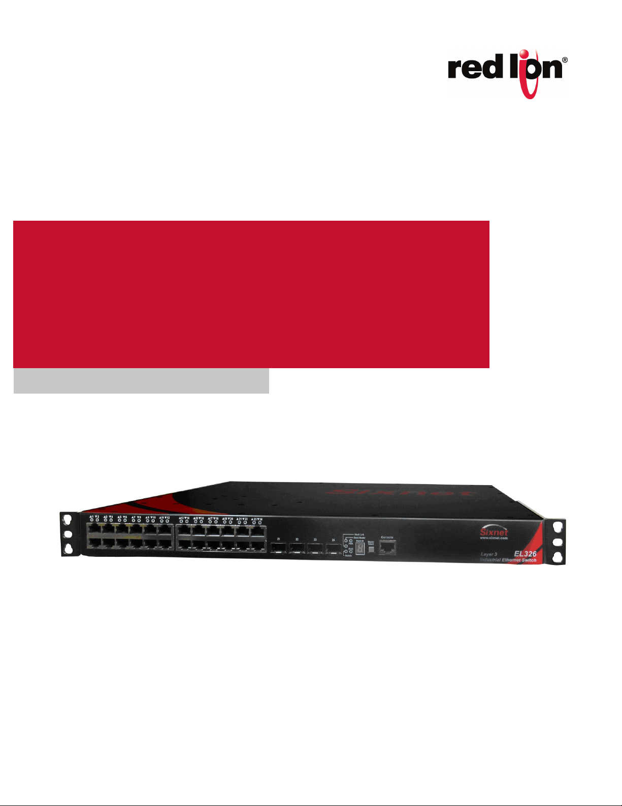
Sixnet® Series EL326
Gigabit Ethernet Switch
Installation
Hardware Guide | August 2015
Page 2

COPYRIGHT
Copyright, © 2015 Red Lion Controls, Inc. All rights reserved. Red Lion, the Red Lion logo and Sixnet are
registered trademarks of Red Lion Controls, Inc. All other company and product names are trademarks of
their respective owners.
Page 3

Table of Contents Revised 2015-08-05
Preface . . . . . . . . . . . . . . . . . . . . . . . . . . . . . . . . . . . . . . . . . . . . . . . . . . . . . . . . . . . . . . . . . . . . . . . . . . . . .iv
Disclaimer . . . . . . . . . . . . . . . . . . . . . . . . . . . . . . . . . . . . . . . . . . . . . . . . . . . . . . . . . . . . . . . . . . . . . . . .iv
Purpose . . . . . . . . . . . . . . . . . . . . . . . . . . . . . . . . . . . . . . . . . . . . . . . . . . . . . . . . . . . . . . . . . . . . . . . . . .iv
Compliance Information . . . . . . . . . . . . . . . . . . . . . . . . . . . . . . . . . . . . . . . . . . . . . . . . . . . . . . . . . . . .iv
Part 15 of the Federal Communications Commission (FCC) - A Rules: Interference . . . . . .iv
Industry Canada . . . . . . . . . . . . . . . . . . . . . . . . . . . . . . . . . . . . . . . . . . . . . . . . . . . . . . . . . . . . . v
Environmental Impact Statement . . . . . . . . . . . . . . . . . . . . . . . . . . . . . . . . . . . . . . . . . . . . . . . v
Toxic Emissions . . . . . . . . . . . . . . . . . . . . . . . . . . . . . . . . . . . . . . . . . . . . . . . . . . . . . . . . . . . . . . v
Trademark Acknowledgments . . . . . . . . . . . . . . . . . . . . . . . . . . . . . . . . . . . . . . . . . . . . . . . . . . . . . . . . v
Release Notes and Document Updates . . . . . . . . . . . . . . . . . . . . . . . . . . . . . . . . . . . . . . . . . . . . . . . . v
Publication History . . . . . . . . . . . . . . . . . . . . . . . . . . . . . . . . . . . . . . . . . . . . . . . . . . . . . . . . . . . v
Related Documents . . . . . . . . . . . . . . . . . . . . . . . . . . . . . . . . . . . . . . . . . . . . . . . . . . . . . . . . . .vi
Document Comments . . . . . . . . . . . . . . . . . . . . . . . . . . . . . . . . . . . . . . . . . . . . . . . . . . . . . . . . vi
Additional Product Information . . . . . . . . . . . . . . . . . . . . . . . . . . . . . . . . . . . . . . . . . . . . . . . . . . . . . .vi
Conventions . . . . . . . . . . . . . . . . . . . . . . . . . . . . . . . . . . . . . . . . . . . . . . . . . . . . . . . . . . . . . . . . . . . . . . vi
Warnings and Cautions . . . . . . . . . . . . . . . . . . . . . . . . . . . . . . . . . . . . . . . . . . . . . . . . . . . . . . . . . . . . .vi
Installation Warnings (Cautions pour Installations) . . . . . . . . . . . . . . . . . . . . . . . . . . . . . . . vii
Hazardous Location Warnings . . . . . . . . . . . . . . . . . . . . . . . . . . . . . . . . . . . . . . . . . . . . . . . . . .ix
Environmental Warnings . . . . . . . . . . . . . . . . . . . . . . . . . . . . . . . . . . . . . . . . . . . . . . . . . . . . . .ix
Fiber Optic Safety . . . . . . . . . . . . . . . . . . . . . . . . . . . . . . . . . . . . . . . . . . . . . . . . . . . . . . . . . . . . x
Hi-Pot (Dielectric) Testing . . . . . . . . . . . . . . . . . . . . . . . . . . . . . . . . . . . . . . . . . . . . . . . . . . . . . x
Section 1 Introduction and Specifications . . . . . . . . . . . . . . . . . . . . . . . . . . . . . . . . . . . . . . . . . . . . . . . . 1
Introduction . . . . . . . . . . . . . . . . . . . . . . . . . . . . . . . . . . . . . . . . . . . . . . . . . . . . . . . . . . . . . . . . . . . . . . 1
Key Features . . . . . . . . . . . . . . . . . . . . . . . . . . . . . . . . . . . . . . . . . . . . . . . . . . . . . . . . . . . . . . . . . . . . . . 1
Product Ordering Guide . . . . . . . . . . . . . . . . . . . . . . . . . . . . . . . . . . . . . . . . . . . . . . . . . . . . . . . . . . . . . 4
General Specifications . . . . . . . . . . . . . . . . . . . . . . . . . . . . . . . . . . . . . . . . . . . . . . . . . . . . . . . . . . . . . . 5
Technical Specifications . . . . . . . . . . . . . . . . . . . . . . . . . . . . . . . . . . . . . . . . . . . . . . . . . . . . . . . . . . . . . 5
LED Indicators . . . . . . . . . . . . . . . . . . . . . . . . . . . . . . . . . . . . . . . . . . . . . . . . . . . . . . . . . . . . . . . . . . . . . 7
All Ports . . . . . . . . . . . . . . . . . . . . . . . . . . . . . . . . . . . . . . . . . . . . . . . . . . . . . . . . . . . . . . . . . . . . 7
Power LEDs . . . . . . . . . . . . . . . . . . . . . . . . . . . . . . . . . . . . . . . . . . . . . . . . . . . . . . . . . . . . . . . . . 8
OK Alarm LED . . . . . . . . . . . . . . . . . . . . . . . . . . . . . . . . . . . . . . . . . . . . . . . . . . . . . . . . . . . . . . . 8
Diagnostic LED . . . . . . . . . . . . . . . . . . . . . . . . . . . . . . . . . . . . . . . . . . . . . . . . . . . . . . . . . . . . . . 8
Stack Link LED . . . . . . . . . . . . . . . . . . . . . . . . . . . . . . . . . . . . . . . . . . . . . . . . . . . . . . . . . . . . . . . 8
Stack Master LED . . . . . . . . . . . . . . . . . . . . . . . . . . . . . . . . . . . . . . . . . . . . . . . . . . . . . . . . . . . . 8
Module LED . . . . . . . . . . . . . . . . . . . . . . . . . . . . . . . . . . . . . . . . . . . . . . . . . . . . . . . . . . . . . . . . 9
Regulatory Approvals and Compliance . . . . . . . . . . . . . . . . . . . . . . . . . . . . . . . . . . . . . . . . . . . . . . . . 10
Limited Warranty . . . . . . . . . . . . . . . . . . . . . . . . . . . . . . . . . . . . . . . . . . . . . . . . . . . . . . . . . . . . . . . . . 11
Sixnet Series EL326 Switch Hardware Guide i
Page 4

Table of Contents Revised 2015-08-05
Section 2 Installation . . . . . . . . . . . . . . . . . . . . . . . . . . . . . . . . . . . . . . . . . . . . . . . . . . . . . . . . . . . . . . . . . 12
Introduction . . . . . . . . . . . . . . . . . . . . . . . . . . . . . . . . . . . . . . . . . . . . . . . . . . . . . . . . . . . . . . . . . . . . . 12
Unpacking . . . . . . . . . . . . . . . . . . . . . . . . . . . . . . . . . . . . . . . . . . . . . . . . . . . . . . . . . . . . . . . . . . . . . . . 12
Inspection . . . . . . . . . . . . . . . . . . . . . . . . . . . . . . . . . . . . . . . . . . . . . . . . . . . . . . . . . . . . . . . . . . . . . . . 12
Installing Mounting Brackets . . . . . . . . . . . . . . . . . . . . . . . . . . . . . . . . . . . . . . . . . . . . . . . . . . . . . . . . 13
Available Brackets . . . . . . . . . . . . . . . . . . . . . . . . . . . . . . . . . . . . . . . . . . . . . . . . . . . . . . . . . . 14
Thermal Considerations . . . . . . . . . . . . . . . . . . . . . . . . . . . . . . . . . . . . . . . . . . . . . . . . . . . . . . . . . . . . 18
Rack Mounting . . . . . . . . . . . . . . . . . . . . . . . . . . . . . . . . . . . . . . . . . . . . . . . . . . . . . . . . . . . . . 18
BTU / Hour . . . . . . . . . . . . . . . . . . . . . . . . . . . . . . . . . . . . . . . . . . . . . . . . . . . . . . . . . . . . . . . . 18
Section 3 Power and Output Wiring . . . . . . . . . . . . . . . . . . . . . . . . . . . . . . . . . . . . . . . . . . . . . . . . . . . . 19
Introduction and Overview . . . . . . . . . . . . . . . . . . . . . . . . . . . . . . . . . . . . . . . . . . . . . . . . . . . . . . . . . 19
Special Order Options: . . . . . . . . . . . . . . . . . . . . . . . . . . . . . . . . . . . . . . . . . . . . . . . . . . . . . . . 19
Redundancy Operation . . . . . . . . . . . . . . . . . . . . . . . . . . . . . . . . . . . . . . . . . . . . . . . . . . . . . . . . . . . . 19
AA Option Operation . . . . . . . . . . . . . . . . . . . . . . . . . . . . . . . . . . . . . . . . . . . . . . . . . . . . . . . . 19
DD Option Operation . . . . . . . . . . . . . . . . . . . . . . . . . . . . . . . . . . . . . . . . . . . . . . . . . . . . . . . . 20
Safety Grounding . . . . . . . . . . . . . . . . . . . . . . . . . . . . . . . . . . . . . . . . . . . . . . . . . . . . . . . . . . . . . . . . . 20
Power Labeling . . . . . . . . . . . . . . . . . . . . . . . . . . . . . . . . . . . . . . . . . . . . . . . . . . . . . . . . . . . . . . . . . . . 21
AC Power Systems . . . . . . . . . . . . . . . . . . . . . . . . . . . . . . . . . . . . . . . . . . . . . . . . . . . . . . . . . . 22
Positive (+) DC Power Systems . . . . . . . . . . . . . . . . . . . . . . . . . . . . . . . . . . . . . . . . . . . . . . . . 22
Negative (-) DC Power Systems . . . . . . . . . . . . . . . . . . . . . . . . . . . . . . . . . . . . . . . . . . . . . . . . 22
Reverse Polarity Protection . . . . . . . . . . . . . . . . . . . . . . . . . . . . . . . . . . . . . . . . . . . . . . . . . . . 22
“OK” Alarm Output . . . . . . . . . . . . . . . . . . . . . . . . . . . . . . . . . . . . . . . . . . . . . . . . . . . . . . . . . . . . . . . . 22
Alarm Output Ratings: . . . . . . . . . . . . . . . . . . . . . . . . . . . . . . . . . . . . . . . . . . . . . . . . . . . . . . . 22
Wire Gauge and Screw Torque . . . . . . . . . . . . . . . . . . . . . . . . . . . . . . . . . . . . . . . . . . . . . . . . . . . . . . 23
Connecting per EN/IEC 61010-1 . . . . . . . . . . . . . . . . . . . . . . . . . . . . . . . . . . . . . . . . . . . . . . . 24
Section 4 Communication Ports Wiring . . . . . . . . . . . . . . . . . . . . . . . . . . . . . . . . . . . . . . . . . . . . . . . . . 25
Introduction . . . . . . . . . . . . . . . . . . . . . . . . . . . . . . . . . . . . . . . . . . . . . . . . . . . . . . . . . . . . . . . . . . . . . 25
Gigabit RJ45 Ports 1-24 . . . . . . . . . . . . . . . . . . . . . . . . . . . . . . . . . . . . . . . . . . . . . . . . . . . . . . . . . . . . 25
RJ45 Cable Distance . . . . . . . . . . . . . . . . . . . . . . . . . . . . . . . . . . . . . . . . . . . . . . . . . . . . . . . . . 26
Gigabit / SFP Ports . . . . . . . . . . . . . . . . . . . . . . . . . . . . . . . . . . . . . . . . . . . . . . . . . . . . . . . . . . . . . . . . 26
SFP Transceivers . . . . . . . . . . . . . . . . . . . . . . . . . . . . . . . . . . . . . . . . . . . . . . . . . . . . . . . . . . . . 27
SFP Transceiver Fiber Wiring Guidelines . . . . . . . . . . . . . . . . . . . . . . . . . . . . . . . . . . . . . . . . 27
Duplex Operation . . . . . . . . . . . . . . . . . . . . . . . . . . . . . . . . . . . . . . . . . . . . . . . . . . . . . . . . . . . 27
Verifying Connectivity . . . . . . . . . . . . . . . . . . . . . . . . . . . . . . . . . . . . . . . . . . . . . . . . . . . . . . . . . . . . . 28
Console Port Management . . . . . . . . . . . . . . . . . . . . . . . . . . . . . . . . . . . . . . . . . . . . . . . . . . . . . . . . . 28
Connecting Switches in a Stack . . . . . . . . . . . . . . . . . . . . . . . . . . . . . . . . . . . . . . . . . . . . . . . . . . . . . . 28
Sixnet Series EL326 Switch Hardware Guide ii
Page 5

Table of Contents Revised 2015-08-05
Switch Stack Connection Procedure . . . . . . . . . . . . . . . . . . . . . . . . . . . . . . . . . . . . . . . . . . . . 29
Installing Optional 10G Switch Module . . . . . . . . . . . . . . . . . . . . . . . . . . . . . . . . . . . . . . . . . 29
Section 5 Hi-Pot Testing and Maintenance . . . . . . . . . . . . . . . . . . . . . . . . . . . . . . . . . . . . . . . . . . . . . . . 31
Introduction . . . . . . . . . . . . . . . . . . . . . . . . . . . . . . . . . . . . . . . . . . . . . . . . . . . . . . . . . . . . . . . . . . . . . 31
Hi-Pot Slot . . . . . . . . . . . . . . . . . . . . . . . . . . . . . . . . . . . . . . . . . . . . . . . . . . . . . . . . . . . . . . . . . . . . . . . 31
Hi-Pot Test . . . . . . . . . . . . . . . . . . . . . . . . . . . . . . . . . . . . . . . . . . . . . . . . . . . . . . . . . . . . . . . . . . . . . . . 32
Maintenance . . . . . . . . . . . . . . . . . . . . . . . . . . . . . . . . . . . . . . . . . . . . . . . . . . . . . . . . . . . . . . . . . . . . . 33
Service Information . . . . . . . . . . . . . . . . . . . . . . . . . . . . . . . . . . . . . . . . . . . . . . . . . . . . . . . . . . . . . . . 33
For Your Convenience: . . . . . . . . . . . . . . . . . . . . . . . . . . . . . . . . . . . . . . . . . . . . . . . . . . . . . . . 34
Sixnet Series EL326 Switch Hardware Guide iii
Page 6

Preface Revised 2015-08-05
Preface
Disclaimer
Portions of this document are intended solely as an outline of methodologies to be followed during the installation
and maintenance of Sixnet Series EL326 Switch equipment. It is not intended as a step-by-step guide or a
complete set of all procedures necessary and sufficient to complete all operations.
While every effort has been made to ensure that this document is complete and accurate at the time of release, the
information that it contains is subject to change. Red Lion Controls is not responsible for any additions to or
alterations of the original document. Industrial networks vary widely in their configurations, topologies, and traffic
conditions. This document is intended as a general guide only. It has not been tested for all possible applications,
and it may not be complete or accurate for some situations.
Users of this document are urged to heed warnings and cautions summarized at the front of the document, such as
electrical hazard warnings.
Purpose
This guide gives specific information on how to properly install and maintain the Sixnet Series EL326 Switch 26port managed layer 3 industrial Ethernet rack-mount switch.
The guide is intended for use by network administrators who are responsible for installing and setting up network
equipment; consequently, it assumes a basic working knowledge of electrical safety and any local, regulatory or
corporate rules for the installation of industrial electrical equipment.
Compliance Information
It is recommended that the owner of this equipment determine and ensure conformance with any specific and
applicable local regulations.
Part 15 of the Federal Communications Commission (FCC) - A Rules: Interference
Every effort has been made to ensure that this equipment is designed to comply with the limits for a Class A digital
device, as described in the FCC Rules.
This product complies with Part 15 of the FCC-A Rules.
Operation is subject to the following conditions:
1. This device may not cause harmful Interference
2. This device must accept any interference received, including interference that may cause undesired operation.
This equipment has been tested and found to comply with the limits for a Class A digital device, pursuant to Part 15
of the FCC Rules. These limits are designed to provide reasonable protection against harmful interference. This
equipment generates, uses, and can radiate radio frequency energy and, if not installed and used in accordance
with the instructions, may cause harmful interference to radio communications. However, there is no guarantee
that interference will not occur in a particular installation. If this equipment does cause harmful interference to radio or television reception, which can be determined by turning the equipment off and on, the
user is encouraged to try to correct the interference by one or more of the following measures:
Sixnet Series EL326 Switch Hardware Guide iv
Page 7

Preface Revised 2015-08-05
• Reorient or relocate the receiving antenna.
• Increase the separation between the equipment and receiver.
• Connect the equipment into an outlet on a circuit different from that to which the receiver is connected.
• Consult the dealer or an experienced radio/TV technician for help.
Note: Shielded interface cable must be used in order to comply with emission limits
Note: Changes or modification not expressly approved by the party responsible for compliance
could void the user’s authority to operate the equipment
Industry Canada
This device complies with the limits of Industry Canada per ICES-003. Operation is subject to the following two
conditions:
• This device may not cause harmful interference, and
• This device must accept any interference received, including interference that may cause undesired opera-
tion.
• ce dispositif peut ne pas causer l'interférence nocive, et
• ce dispositif doit accepter n'importe quelle interférence reçue, y compris l'interférence qui peut causer
l'opération peu désirée.
Environmental Impact Statement
Red Lion equipment contains no hazardous materials as defined by the United States Environmental Protection
Agency (USEPA). Red Lion recommends that all failed product be returned to Red Lion for failure analysis and
proper disposal.
Toxic Emissions
Red Lion equipment releases no toxic emissions.
Trademark Acknowledgments
All trademarks are the property of their respective owners.
Release Notes and Document Updates
The hard copy and electronic media versions of this document are revised only at major releases and therefore,
may not always contain the latest product information. As needed, Documentation Notes and or Product Bulletins
will be provided between major releases to describe any new information or document changes.
The latest online version of this document and all product updates can be accessed through the Red Lion web site
at http://www.redlion.net
Publication History
The following information lists the release history of this document.
Sixnet Series EL326 Switch Hardware Guide v
Page 8
Preface Revised 2015-08-05
ISSUE/REVISION RELEASE DATE CONTENT DESCRIPTION
Released September 2013 First Release
Revised August 2015
Revised Format and structure. Added OK Alarm Output
Relay table.
Related Documents
The following publication details the software features of the switch, including the Web interface, CLI and much
more:
• EL326 Software Manual
Also, as part of the switch’s software, there is an online web-based help that describes all management related features.
isit the Technical Resources page on the Red Lion website at the following link to view available documents
V
related to this product.
http://www.redlion.net/documentation/red-lion-documentation
Document Comments
Red Lion appreciates all comments that will help us to improve our documentation quality. The user can submit
comments through the Red Lion Customer Service. Simply email us at customer.service@redlion.net.
Additional Product Information
Additional product information can be obtained by contacting the local sales representative or Red Lion through the
contact numbers and/or e-mail addresses listed on the inside of the front cover.
Conventions
The following conventions are used throughout this guide to display information:
Note: Emphasizes important information or calls your attention to related features or instructions.
Caution: Alerts you to a potential hazard that could cause loss of data, or damage the system or
equipment. Documentation must be consulted in all cases where caution is indicated.
Warning: Alerts you to a potential hazard that could result in serious personal injury.
Sixnet Series EL326 Switch Hardware Guide vi
Page 9
Preface Revised 2015-08-05
Warnings and Cautions
Please read the following safety information carefully before installing or performing any maintenance on the
switch. The safety of any system incorporating this equipment is the responsibility of the assembler of the system.
S'il vous plaît lire attentivement les consignes de sécurité suivantes avant d'installer ou d'effectuer un entretien sur
l'appareil. La sécurité de tout système intégrant cet équipement est la responsabilité de l'assembleur du système.
Installation Warnings (Cautions pour Installations)
WARNING: These products should not be used to replace proper safety interlocking. No softwarebased device (or any other solid-state device) should ever be designed to be responsible for the
maintenance of consequential equipment or personnel safety. In particular, Red Lion disclaims
any responsibility for damages, either direct or consequential, that result from the use of this
equipment in any application. All power, input and output (I/O) wiring must be in accordance with
Class I, Division 2 wiring methods and/or in accordance with the authority having jurisdiction.
Refer to section 1 for other important installation warnings. This equipment is suitable for use in
Class I, Division 2, Groups A, B, C, D or non-hazardous locations only.
AVERTISSEMENT: Ces produits ne doivent pas être utilisés pour remplacer le verrouillage de
sécurité approprié. Aucun dispositif basé sur un logiciel (ou tout autre dispositif à l'état solide)
devraient jamais être conçus pour être responsable de l'entretien de l'équipement consécutifs ou
la sécurité du personnel. En particulier, Red Lion décline toute responsabilité pour les dommages,
directs ou indirects, résultant de l'utilisation de cet équipement dans n'importe quelle application.
Tout courant, câblage entrée et sortie (I / O) doit être conforme aux méthodes de câblage à la
Classe I, Division 2 et conformément à l'autorité compétente. Référer à la section 1 pour les
autres avertissements d’installations importantes. Cet équipement est adapté à une utilisation en
Classe I, Division 2, Groupes A, B, C, D ou environnements non dangereux seulement.
WARNING: Do not perform any services on the unit unless qualified to do so. Do not substitute
unauthorized parts or make unauthorized modifications to the unit.
AVERTISSEMENT: Ne pas effectuer de services sur l'appareil s'il n'est pas qualifié pour le faire. Ne
pas substituer pièces non autorisées ou de modifications non autorisées de l'appareil.
WARNING: Install only in accordance with Local and National Codes of authorities having
jurisdiction.
AVERTISSEMENT: Installer uniquement, conformément aux codes locaux et nationaux des
autorités ayant compétence.
WARNING: Properly ground the unit before connecting anything else to the unit. Units not
properly grounded may result in a safety risk and could be hazardous and may void the warranty.
See the grounding technique section of this Hardware Guide for proper ways to ground the unit.
AVERTISSEMENT: Correctement à la terre de l'unité avant tout raccordement à l'unité. Unités pas
correctement mise à la terre peut entraîner un risque de sécurité et pourraient être dangereux et
peut annuler la garantie. Voir la section technique de mise à la terre de ce mode d'emploi des
moyens appropriés à la masse de l'appareil.
Sixnet Series EL326 Switch Hardware Guide vii
Page 10
Preface Revised 2015-08-05
CAUTION: If the Sixnet series equipment is used in the manner not specified by Red Lion, the
protection provided by the equipment may be impaired.
AVERTISSEMENT: Si l' Sixnet série équipement est utilisé d'une manière non spécifiée par Red
Lion, la protection fournie par l'équipement peut être compromise.
WARNING: Do not connect to an AC power supply without an earth ground.
AVERTISSEMENT: Ne pas se connecter à une source d'alimentation CA sans une prise de terre.
WARNING: This product does not contain any user serviceable parts.
AVERTISSEMENT: Ce produit ne contient pas de pièces réparables par l'utilisateur.
WARNING: Do not work on equipment or cables during periods of lightning activity.
AVERTISSEMENT: Ne pas travailler sur le matériel ou les câbles pendant les périodes d'activité de
la foudre.
WARNING: Do not connect a telephone line into one of the Ethernet RJ45 connectors.
AVERTISSEMENT: Ne branchez pas une ligne téléphonique dans l'un des connecteurs RJ45
Ethernet.
WARNING: Substitution of any components may impair suitability for Class I, Division 2
(Zone 2) areas.
AVERTISSEMENT: La substitution de tout composant peut nuire à la conformité de Classe
I, Division 2 (Zone 2).
Hazardous Location Warnings
WARNING (explosion hazard): When in hazardous locations, disconnect power before
servicing units.
AVERTISSEMENT (risque d’explosion): Lorsque dans des endroits dangereux, débran-
chez le cordon d’alimentation avant de remplacer ou de brancher des modules.
Sixnet Series EL326 Switch Hardware Guide viii
Page 11
Preface Revised 2015-08-05
WARNING (explosion hazard): Do not disconnect equipment unless power has been
switched off or area is known to be nonhazardous.
AVERTISSEMENT (risque d’explosion): Ne débranchez pas l’équipement pendant que le
circuit est direct ou à moins que l’environnement soit connu pour être libre de concentrations inflammables.
WARNING (explosion hazard): In hazardous or potentially hazardous locations, do not
separate any part of unit when energized. Use the unit for internal connections only.
AVERTISSEMENT (risque d’explosion): Dans les endroits dangereux ou potentiellement
dangereux, ne pas séparer une partie de l'unité sous tension. Seulement utilisez l'appareil pour les connexions internes.
WARNING (explosion hazard): No hot swapping of modules in Hazardous Locations.
AVERTISSEMENT (risque d’explosion): Pas de remplacement à chaud des modules
dans les zones dangereuses.
Environmental Warnings
WARNING: Exposure to some chemicals may degrade the sealing properties of materi-
als used in the Sealed Relay Device.
AVERTISSEMENT: L’exposition à certains produits chimiques peut dégrader les propriétés
d'étanchéité des matériaux utilisés dans les relais étanche périphérique.
WARNING: Field Wiring conductor minimum insulation rating: 75°C.
AVERTISSEMENT: Isolation minimale pour câblage de conducteur de terrain: 75°C
(167°F).
WARNING: Device is open-type and is to be installed in an enclosure suitable for the
environment.
AVERTISSEMENT: L’appareil est type ouvert et doit être installé dans un boîtier adapté à
l’environnement et accessible par outil seulement.
Sixnet Series EL326 Switch Hardware Guide ix
Page 12
Preface Revised 2015-08-05
Fiber Optic Safety
WARNING: When using fiber optic ports, never look at the transmit laser, fiber TX port or fiber
cable ends while the switch is powered on. It is highly recommended to keep the rubber fiber plugs
inserted when the fiber port is not being used
.
Hi-Pot (Dielectric) Testing
CAUTION: The EL326-AO/AA-1 devices are designed to withstand a high-potential “hi-pot”
(dielectric) test up to 2000 VAC or 2800 VDC (1 minute), or 2400 VAC or 3300 VDC (1 second)
according to IEEE 1613. However, the surge circuitry must be bypassed before performing this
test. See Section 5 for details.
CAUTION: The EL326-DD/DO-1 devices are designed to withstand a high-potential “hi-pot”
(dielectric) test up to 500 VAC (1 minute) or 707 VDC (1 minute) on the inputs (P1 and P2)
according to IEEE 1613. However, the surge circuitry must be bypassed before performing this
test. See Section 5 for details.
POWER MARKINGS
Direct Current (DC)
Alternating Current
Protective Conductor Terminal
Sixnet Series EL326 Switch Hardware Guide x
Page 13

Introduction and Specifications Revised 2015-08-05
Section 1 Introduction and Specifications
Introduction
The Red Lion Sixnet Series EL326 is a 26 port industrial Ethernet managed switch designed to meet the extreme
requirements of power substations, traffic control, railway and other harsh environments. It combines the high performance and security of an enterprise-class switch with rugged packaging and protected circuitry to meet the
needs of the most demanding applications.
This manual will help you install and maintain these industrial Ethernet switches. Installation of these switches is
very easy and they will begin to operate as soon as they are powered up. Though these are fully managed
switches, they will act as unmanaged until they are configured otherwise. Refer to the separate software manual or
management guide for configuration of the advanced networking functionality and security
Note: This manual only covers the installation and wiring of these switches. Refer to the separate
Management Guide for details on configuring and using any of the management functions such as
SNMP, RSTP, IGMP, VLANs, security, port mirroring and much more.
Unlike an Ethernet hub that broadcasts all messages out all ports, these industrial Ethernet switches will intelligently route Ethernet messages only out the appropriate port. The major benefits of this are increased bandwidth
and speed, reduction or elimination of message collisions, and deterministic performance when tied with real-time
systems.
These industrial Ethernet switches support 10BaseT (10 Mbps), 100BaseT (100 Mbps) and 1000BaseT
(1000Mbps) on the first 24 ports via standard RJ45 connectors. These ports will independently auto-sense the
speed/duplex and mdi/mdix-crossover allowing you to use straight or crossed-wired cables. Ports 21-24 are combination ports and also provide SFP cages that accept industry-standard pluggable SFP transceivers of various
types including multimode, singlemode, long-haul, bidi and more. These pluggable SFP ports support 100/
1000BaseF (100/1000 Mbps) noise-immune fiber connections up to 120km.
General Features
The general features list presented in Table 1-1 apply to these industrial Ethernet switches. Refer to the next section for a list of key features.
Sixnet Series EL326 Switch Hardware Guide 1
Page 14
Introduction and Specifications Revised 2015-08-05
NUMBER OF PORTS
ETHERNET SWITCH TYPE
ETHERNET SWITCH MODE
ETHERNET PROTOCOLS
PORTS 1 THROUGH 20
PORTS 21 AND 24
RJ45 PORTS OPERATION
FIBER OPTIC TYPE
PACKAGE STYLE
Table 1-1.
26 Ethernet ports
Managed
Store and forward, wire-speed, non-blocking
All standard IEEE 802.3 protocols supported
Gigabit RJ45 ports for 10/100/1000 Mbps connections
Gigabit SFP slots with both RJ45 (10/100/1000) or 100 or 1000 Mbps fiber transceivers
Auto-negotiation, auto-mdi/mdix-crossover and auto-polarity
Multimode, singlemode, long-haul or special application
1U 19” rack mount
EL326 General Specification
Key Features
• Ethernet Performance
• 26 total Ethernet ports plus 2 expansion bays
• 2 Optional 10G fiber XFP ports
• 24 10/100/1000 Ethernet RJ45 ports 1-24
• 4 Gigabit RJ45/SFP combo ports 21-24
• RJ45 ports: auto-negotiation (speed/duplex) and auto-crossover
• Non-blocking, store and forward, wire-speed
• Switching capacity and forwarding rate: 128 Gbps / 95 Mpps
• MAC address table size: 16K
• Jumbo frame: 9K
• Ethernet isolation: 1500 Vrms 1 minute
• Switching Features
• Flow control: IEEE 802.3x (Full Duplex) & Back-Pressure (Half Duplex)
• Spanning Tree Protocol (STP per IEEE 802.1D) plus
• IEEE 802.1w Rapid Spanning Tree Protocol (RSTP)
• IEEE 802.1s Multiple Spanning Tree Protocol (MSTP) BPDU forwarding and filtering
• Virtual Local Area Networks (VLANs)
• 802.1Q tag-based with 256 VLANs and 4K VLAN ID
• 802.1v protocol and port-based VLAN
• Voice and Private VLAN
• QVRP and Q-in-Q (double tagging)
• Link Aggregation Control Protcol (LACP per IEEE 802.3ad)
• Static trunk (8 trunks and up to 8 ports per trunk)
• Traffic load balancing
Sixnet Series EL326 Switch Hardware Guide 2
Page 15

Introduction and Specifications Revised 2015-08-05
• Internet Group Management Protocol (IGMP)
• IGMP v1, v2 and v3 with up to 255 multicast groups
• IGMP snooping and querying
• Immediate leave and leave proxy
• Throttling and filtering
• Multicast VLAN Registration (MVR)
• IEEE 802.1ab Link layer Discovery Protocol (LLDP)
• Quality of Service (QoS) with 4 priority queues
• Scheduling schemes: WRR and Strict priority
• CoS per IEEE 802.1p and IP DSCP-based
• DiffServ (DS): ingress, egress and remarking
• Rate limiting (ingress and egress)
• 64Kbps to 100/1000Mbps
• Per port CoS
• Routing Features
• Host table: 8K
• Route table: 8K
• Static route table: 512
• Multicast table: 1K
• Unicast routing
• Static unicast routes
• RIP v1/v2
• OSPF
• BGP
• Mulitcast routing
• PIM-DM
• PIM-SM
• IGMP v1/v2/v3
• IGMP v3 proxy
• IP Redundancy
• Proxy ARP
• UDP Helper
• Security Features
• Enable / disable ports
• Port security (MAC-based): static and dynamic
• DHCP Snooping and Option 82
• IP Source Guard
Sixnet Series EL326 Switch Hardware Guide 3
Page 16

Introduction and Specifications Revised 2015-08-05
• IEEE 802.1x Network Access Control
• Port-based with single or multiple host mode
• Authentication: EAP-MD5, PEAP, TLS, TTLS
• MAC and web authentication
• Guest VLAN and Auto VLAN assignment
• RADIUS and TACACS AAA
• Authentication, Accounting and Authorization
• 5 servers for RADIUS, 1 server for TACACS
• Encryption: MD5, TLS, TTLS, TACACS AAA/3.0
• Access Control List (ACL)
• IP and MAC-based
• VLAN and TCP/UDP port
• Storm Control for broadcast and multicast messages
• HTTPS/SSL for secure Web access
• SSH v1.5/2.0 for secure Telnet access
• SNMPv3 authentication and encryption
• Username and password authentication
• Management access filtering
• Management and Monitoring Features
• IP Address assignment: Static, DHCP and BOOTP
• CLI (Command Line Interface) via console or Telnet
• Web interface (HTTP/HTTPS/SSL)
• SNMP v1, v2, v3 (Simple Network Management Protocol)
• SNMP Traps for event notification
• RMON (Remote Monitoring): Groups 1, 2, 3 and 9
• sFlow network-wide traffic monitoring
• Dual firmware update system
• Configuration download and upload
• Software upgrade via TFTP
• Port mirroring
• Event / Error / System log
• Local flash
• Remote server via system log (Syslog RFC 3164)
• SMTP (RFC 821) email alarming
• Network Time Protocol for time synchronization
• SNTP (RFC 2030) and NTP (RFC 1305)
• DNS (Domain Name Server) client
• Universal Plug and Play (UPnP)
• IEEE 802.3ah OAM (Operational Administration Maintenance)
• Banner commands
Sixnet Series EL326 Switch Hardware Guide 4
Page 17

Introduction and Specifications Revised 2015-08-05
Product Ordering Guide
The Sixnet Series EL326 Switch model part numbers and available accessories are presented in Table 1-2.
Table 1-2. Ordering Guide
PART NUMBER DESCRIPTIOM
EL326-AO-1
EL326-DO-1
EL326-AA-1
EL326-DD-1
26 ports (20 copper GigE, four copper or SFP fiber GigE, and two optional 10 GigE via XFP);
Single power input for 85-264 V
26 ports (20 copper GigE, four copper or SFP fiber GigE, and two optional 10 GigE via XFP);
Single power input for 20-59 VDC (absolute minimum and maximum)
26 ports (20 copper GigE, four copper or SFP fiber GigE, and two optional 10 GigE via XFP);
Dual power input for 85-264 V
26 ports (20 copper GigE, four copper or SFP fiber GigE, and two optional 10 GigE via XFP);
Dual power input for 20-59 VDC (absolute minimum and maximum)
AC or 90-300 VDC (absolute minimum and maximum)
AC or 90-300 VDC (absolute minimum and maximum)
Technical Specifications
The specifications presented in Table 1-3 are subject to change. Contact Red Lion for the latest details. Refer to
the software user manual or data sheet for complete software specifications.
Sixnet Series EL326 Switch Hardware Guide 5
Page 18

Introduction and Specifications Revised 2015-08-05
Table 1-3. EL326 Technical Specifications
POWER INPUT and ALARM OUTPUT
• Dual-redundant internal power supplies (optional)
• 10-pole screw block can be positioned in front or back
• Power input options:
• +/-24-48 VDC (Doption)
(absolute min and max: +/-20-59 VDC)
• +/-110-250 VDC or 100-240 VAC (50/60 Hz) A option
(absolute min and max: +/-90-300 VDC or 85-264 VAC (50/60 Hz)
• Power consumption:
• 120 Watts typ. w/ all ports linked
• Protection: current overload and reverse polarity
• Alarm output: form-C relay (NO and NC contacts)
• Max. voltage: 250 VAC, 30 VDC
• Max. current: 2A @ 30 VDC or 250 VAC
MECHANICAL
• Rack or wall mounting:
• 1U rack mount (19” brackets included)
• Optional 23”, 24", EIA, WECO, ETSI and wall brackets available
• Ingress protection: IP50 sealed from dust and contaminants
• Heavy-gauge corrosion-resistant metal enclosure
• Dimensions (HxWxD): 1.75(1U)x17.3x13” (45x439x330mm)
• Weight (typical): 5.5 lbs (2.5 kg)
ENVIRONMENTAL
• Operating temperature: -35° to +80˚C per IEC 60068-2-1/2
• DD/D0 models: -35° to +75°C per IEC 60068-2-1/2
• Storage temperature: -40° to +85˚C
• Cold startup: -35°C except with 10G module then -5°C
• Humidity: 5 to 95% RH (non-condensing)
• Vibration: 20mm/s from 1 to 150 Hz per IEEE 1613 Class V.S.3
• Vibration: Amp: 3mm from 2-9 Hz, 1g from 9-200Hz, 1.5g from 200-500 Hz per IEC 61850-3
• Shock: 30g @ 11ms per IEC 61850-3
EMC and STANDARDS COMPLIANCE
• EMC immunity: IEC 61850-3, IEC 61000-6-2/4, CE
• EMC emissions: FCC Part 15; EN 55022 (CISPR22), CE
• Safety: UL508 /ANSI / ISA12.12.01 / CSA C22.2 No. 142 and No. 213
• UL temperature specs: EL326-AA/AO-1, T4 @ 80C EL326-DD/DO-1, T4 @ +75C
• IEC61010-1, CE
• RoHS, WEEE and CE compliant
• ISO9001:2008 certified company
Sixnet Series EL326 Switch Hardware Guide 6
Page 19

Introduction and Specifications Revised 2015-08-05
• MTBF A0/D0 models: 178,274 Hours GB @ 40˚C per MIL-HNDBK-217F2
• MTBF AA/DD models: 174,264 Hours GB @ 40˚C per MIL-HNDBK-217F2
LED Indicators
The EL326 switches have the following number and types of indicators (see Figure 1-1):
• 1 Communication LED for each port
• 3 Power LEDs (P1, P2 and PWR)
• 1 “OK” output LED
• 1 Diagnostic LED
• 1 Stack Link LED
• 1 Stack Master LED
• 1 Module LED
Figure 1-1. LED Locations
All Ports
All 26 ports each have only 1 LED. Regardless of the type of port (RJ45 versus SFP) or type of transceiver the
LED states and definitions are presented in Table 1-4.
Table 1-4. Port LED States
LED STATE DEFINITION
Green LED ON Solid
Green LED ON Flashing
OFF
Link Only - Indicates that there
communications activity is detected.
Link & Activity - Indicates that there
and communications activity is detected.
No link - Indicates that there
sure the cable has been properly connected at both ends.
is a proper Ethernet connection (Link) but no
is a proper Ethernet connection (Link)
is not a proper Ethernet connection (Link). Make
Power LEDs
There are three Power LEDs (labeled Pwr 1 for primary power and Pwr 2 for backup power) that indicate if there is
power applied to the respective input. There is also an overall Pwr LED in the front.
Sixnet Series EL326 Switch Hardware Guide 7
Page 20

Introduction and Specifications Revised 2015-08-05
OK Alarm LED
The “OK” LED indicates loss of primary power.
Diagnostic LED
The DIAG (Diagnostic) LED states and definitions are presented in Table 1-5.
Table 1-5. DIAG LED States
LED STATE DEFINITION
Flashing Green System self-diagnostic test in progress.
Green
Amber System self-diagnostic test has detected a fault.
System self-diagnostic test successfully
completed
Stack Link LED
The Stack Link LED states and definitions are presented in Table 1-6.
Table 1-6. Stack Link LED States
LED STATE DEFINITION
Green Uplink and downlink operating normally.
Flashing Green Uplink has failed.
Flashing Amber Downlink has failed.
Amber No stacking link is present.
Stack Master LED
The Stack Master LED states and definitions are presented in Table 1-7.
Table 1-7. Master Stack LED States
LED STATE DEFINITION
Green
Flashing Green Switch is the Master unit of the stack, system is initializing.
Amber Switch is operating as a Slave unit in the stack.
Flashing Amber System in Master arbitration/election state.
Off There is no module installed.
Switch is the Master unit of the stack. State may include topology discovery,
IP assignment, or normal operations.
Module LED
The Module LED states and definitions are presented in Table 1-8.
Sixnet Series EL326 Switch Hardware Guide 8
Page 21

Introduction and Specifications Revised 2015-08-05
Table 1-8. Module LED States
LED STATE DEFINITION
Green
Amber An expansion module is installed but has failed.
Off There is no module installed.
An expansion module is installed and operating normally.
Sixnet Series EL326 Switch Hardware Guide 9
Page 22

Introduction and Specifications Revised 2015-08-05
Regulatory Approvals and Compliance
These industrial Ethernet Switches meet the following standards plus others:
Red Lion Controls, Inc, is an ISO9001:2008 certified company (FM 65232). These devices are
designed, developed and manufactured per an ISO9001 quality management system.
Electrical safety
These devices have been designed to meet the basic safety requirements of the following standards:
- CE per Low Voltage Directive and IEC 61010-1
- UL508 (Industrial control equipment), ANSI / ISA12.12.01 (Hazardous Locations)
- CSA C22.2 No. 142 and No. 213 (per cUL)
EMC (emissions and immunity)
· CE per the EMC directive
· IEC 61000-6-2: Immunity in industrial environments
· IEC 61000-6-4: Emissions in industrial environments
· FCC part 15 and ICES 003. See FCC statement on page 6.
EN 55022 (CISPR22)
WEEE compliance
These devices comply with the WEEE directive. Do not throw away these devices in the standard
trash. Contact Red Lion regarding proper disposal.
RoHS compliance
These devices comply with the RoHS directive and are considered lead and other hazardous substance free.
Sixnet Series EL326 Switch Hardware Guide 10
Page 23

Introduction and Specifications Revised 2015-08-05
Limited Warranty
(a) Red Lion Controls Inc., Sixnet Inc., N-Tron Corporation, or Blue Tree Wireless Data, Inc. (the “Company”) warrants that all Products shall be free from defects in material and workmanship under normal use for the period of
time provided in “Statement of Warranty Periods” (available at www.redlion.net) current at the time of shipment of
the Products (the “Warranty Period”). EXCEPT FOR THE ABOVE-STATED WARRANTY, COMPANY MAKES NO
WARRANTY WHATSOEVER WITH RESPECT TO THE PRODUCTS, INCLUDING ANY (A) WARRANTY OF
MERCHANTABILITY; (B) WARRANTY OF FITNESS FOR A PARTICULAR PURPOSE; OR (C) WARRANTY
AGAINST INFRINGEMENT OF INTELLECTUAL PROPERTY RIGHTS OF A THIRD PARTY; WHETHER
EXPRESS OR IMPLIED BY LAW, COURSE OF DEALING, COURSE OF PERFORMANCE, USAGE OF TRADE
OR OTHERWISE. Customer shall be responsible for determining that a Product is suitable for Customer’s use and
that such use complies with any applicable local, state or federal law.
(b) The Company shall not be liable for a breach of the warranty set forth in paragraph (a) if (i) the defect is a result
of Customer’s failure to store, install, commission or maintain the Product according to specifications; (ii) Customer
alters or repairs such Product without the prior written consent of Company.
(c) Subject to paragraph (b), with respect to any such Product during the Warranty Period, Company shall, in its
sole discretion, either (i) repair or replace the Product; or (ii) credit or refund the price of Product provided that, if
Company so requests, Customer shall, at Company's expense, return such Product to Company.
(d) THE REMEDIES SET FORTH IN PARAGRAPH (c) SHALL BE THE CUSTOMER'S SOLE AND EXCLUSIVE
REMEDY AND COMPANY'S ENTIRE LIABILITY FOR ANY BREACH OF THE LIMITED WARRANTY SET
FORTH IN PARAGRAPH (a).
Sixnet Series EL326 Switch Hardware Guide 11
Page 24

Installation Revised 2015-08-05
Section 2 Installation
Introduction
This sections contains the information and procedures necessary to unpack, inspect, install and connect the
Sixnet Series EL326 Switch equipment.
These industrial Ethernet switches are designed to be mounted in an industry standard rack or directly to any flat
surface indoors. Each switch is supplied with a standard set of 19” (EIA) rack mounting brackets. Optionally, other
mounting brackets are available. See “Installing Mounting Brackets” on page 13 for details on utilizing the mounting
brackets.
Note: Make sure to read “Thermal Considerations” on page 18 before installing your switch.
Figure 1-1 shows an EL326 in front style arrangement (ports in front and power in the back) mounted in a typical
19” rack, prior to wiring.
Figure 1-1. EL326 Front Style Arrangement
Note: When you are choosing your mounting option make sure to allow enough room to route your
Ethernet copper or fiber optic cables. Also, please consult the specifications for your fiber optic
cable to make sure you allow for the proper bend radius.
Unpacking
Remove all the equipment from the packaging, and store the packaging in a safe place.
Inspection
Please ensure the shipping package contains the following items in undamaged condition:
1. EL326 Switch
2. Standard set of 19” mounting brackets
3. Switch power cord.
4. RJ45 to DB9 adapter console cable
Sixnet Series EL326 Switch Hardware Guide 12
Page 25

Installation Revised 2015-08-05
If the package contents are damaged:
1. Contact your carrier.
2. File any damage claims with the carrier.
Installing Mounting Brackets
There are many options for mounting the industrial Ethernet switches. Each switch is supplied with a standard set
of 19” rack mounting brackets. Optionally, mounting brackets for 23”, 24” and ETSI width racks are available.
These mounting brackets universally support the mounting hole spacing per the EIA (1.25”), ETSI (25mm) and
WECO (1.00”) standards. Refer to the mechanical diagram in Figure 1-5 on page 17 for details.
There are eight threaded inserts (see red arrows in Figure 1-2) on each side of the switch that allow the brackets to
be mounted in numerous positions for the best fit in your rack. The brackets also have extra holes (see blue arrows
above) allowing them to be shifted right or left 1/2 inch. Use the supplied screws to mount the bracket in the
desired position. Plastic screws are also provided to plug the unused holes. See below for possible mounting positions.
Figure 1-2. Threaded Inserts
The brackets are shown mounted flush with the front of the switch in Figure 1-3 (on the left) and the brackets
shown mounted so the front of the switch is setback 1/2 inch (on the right).
Figure 1-3. Brackets Front Flush or Setback Mounted
For the most durable mounting use two brackets on each side, front and back (as shown in Figure 1-4). This
mounting option is ideal for applications requiring the highest shock and vibration resistance.
Sixnet Series EL326 Switch Hardware Guide 13
Page 26

Installation Revised 2015-08-05
Figure 1-4. Brackets Double Mounting
Available Brackets
The available mounting bracket types and mechanical dimensions are provided in Table 1-1 and Figure 1-5.
Sixnet Series EL326 Switch Hardware Guide 14
Page 27

Installation Revised 2015-08-05
Table 1-1. Available Brackets
PART DESCRIPTION PART NUMBER FIGURE
Standard 19” bracket
EK1-BRCKT-19
(set of two)
Optional ETSI bracket
(set of two)
Optional 23” bracket
(set of two)
EK1-BRCKT-ETSI
EK1-BRCKT-23
Sixnet Series EL326 Switch Hardware Guide 15
Page 28

Installation Revised 2015-08-05
Optional 23/24” bracket
(set of two)
Optional wall bracket
(set of two)
EK1-BRCKT-2324
EK1-BRCKT-WALL
Note: AutoCAD and other drawings are available on the CD or at:www.redlion.net
Sixnet Series EL326 Switch Hardware Guide 16
Page 29

Installation Revised 2015-08-05
Figure 1-5. Mechanical Dimensions for the EL326 and Brackets
Sixnet Series EL326 Switch Hardware Guide 17
Page 30

Installation Revised 2015-08-05
Thermal Considerations
The EL326 switches are designed to operate from -35 to +80˚C when they are installed properly. The switch is
cooled via conduction and radiation. There are no fans. Instead there are various heat-sinks inside the switch to
conduct the heat from the components to the heavy-gauge aluminum case. The heat is then dissipated from the
case via radiation to the surrounding air.
Rack Mounting
When the switch is rack mounted, for best heat dissipation it is recommended that there be approximately 1/2RU or
more of free air space above and below the switch (as shown in Figure 1-6). This allows the heat to radiate to the
air. Any moving air in your rack will improve dissipation of the switch generated heat.
Note: An air gap is not absolutely necessary but highly recommended when you know that the
switch will experience high heat (> 60˚C) for extended periods of time.
Figure 1-6. EL326 Rack Mounting Recommendation
Note: If your space is limited and you must choose between an air gap on the bottom versus an air
gap on the top it is better to have the air gap on the top
BTU / Hour
The power consumption of the switch can be as much as 120 Watts with all ports linked and active. Based on this,
the heat dissipation can be as much as 408 BTU per hour. Please plan your system accordingly.
Sixnet Series EL326 Switch Hardware Guide 18
Page 31

Power and Output Wiring Revised 2015-08-05
Section 3 Power and Output Wiring
WARNING: : Please read this section fully before connecting your power input or alarm
output! The unit must be powered down and the power plug removed before any wiring
is done to the power plug. Otherwise, there is a risk of electrical shock if the rules and
warnings in this manual are not properly adhered too.
Introduction and Overview
The EL326 switches are available with several power options including dual power supplies that can keep the
switch running when there is a power input failure or internal power supply failure. Refer to Table 1-1 for the available standard power supply options.
Table 1-1.
OPTION INTERNAL POWER SUPPLY POWER SOURCE TO P1/P2 CONNECTOR
Option A0
Option AA
Option D0
Option DD
Note: With the dual options the two power supplies are completely isolated so each input/supply
can be connected to a different voltage as long as it is in the range for that supply.
single 100-240 (50/60 Hz) VAC power or 110/
250 VDC power
dual 100-240 (50/60 Hz) VAC power or 110250 VDC power
single +/-24/48 VDC power inputs P1 accepts +/-20 to 59 VDC (min/max)
dual +/-24/48 VDC power inputs Both P1 & P2 accept +/-20 to 59 VDC (min/
Standard Power Supply Options
P1 accepts 85-264 VAC or 90 to 300 VDC
(min/max)
P1 & P2 accept 85-264 VAC or 90 to 300
VDC (min/max)
max)
Special Order Options:
Other power input options may be available. Contact Red Lion for details.
Redundancy Operation
The AA and DD power supply options offer dual redundant power supplies built into the switch. This protects your
system from both power input failures and internal power supply failures. Please note that the AA and DD have different default modes of operation
AA Option Operation
The AA option provides dual high voltage power inputs. These inputs are load shared so each input shares around
50% of the load under normal operating conditions. If a power input or supply fails then the other one will handle
100% of the load.
Sixnet Series EL326 Switch Hardware Guide 19
Page 32

Power and Output Wiring Revised 2015-08-05
DD Option Operation
The DD option provides dual low voltage power inputs. These inputs operate in a primary/backup scheme. The P1
input should be connected to the primary power source and the P2 input to the backup power source (such as a
battery). Under normal operating conditions all the power is drawn from the P1 input and supply. Only if P1 fails is
power drawn from the P2 backup input and supply.
Note: These default modes of operation can be changed at the factory. Contact Red Lion for
details.
CAUTION: Make certain you know what type of power your switch accepts and ensure
your input power is within the ranges as defined in this section. Applying the wrong
input power may result in damage to your switch.
Safety Grounding
For the highest electrical safety the EL326 switches are provided with several grounding points. First, there are two
green ground screws (see Figure 1-1) that attach directly to the switch case. These screws can be used to provide
a NEBS compliant safety ground. Please follow all the NEBS grounding rules and your own local requirements
(which are not documented in this manual) to ensure the safe operation of the switch. Alternatively, the power plug
has a chassis ground terminal (#4) that can be used to safety ground the switch. This terminal is internally tied to
the switch case. In addition, there is a ground terminal for each power input. Use these to terminate the ground
wire for each of your power inputs.
Figure 1-1. Switch Case Grounding Screws
Sixnet Series EL326 Switch Hardware Guide 20
Page 33

Power and Output Wiring Revised 2015-08-05
Note: The 2 Safety Guard Screws are designed to be used with Ring Lug Terminals. Do not wrap
ground wire around either of the safety ground screws.
WARNING: It is recommended you make your safety ground connections first before
connecting any power to the switch. Ensure that all power is off before making any
power or ground connections to the switch.
Power Labeling
The power headers and/or plugs are labeled to guide you in properly connecting your power (see Figure 1-2).
Make sure to reference this labeling when wiring your switch to ensure you are connecting the appropriate power
to the correct terminals (see Figure 1-3). If your switch does not have dual power inputs then do not connect anything to the terminals labeled Power 2. The power header/plug connectors are rated for 300V, 10A and 105C.
Figure 1-2. Power Header and Plug Labeling
Figure 1-3. Power Wiring
Sixnet Series EL326 Switch Hardware Guide 21
Page 34

Power and Output Wiring Revised 2015-08-05
AC Power Systems
For AC powered systems the terminals will be labeled as “+/L” for Line (aka Hot), “-/N” for Neutral and the chassis
ground symbol for ground. Connect your AC power input as correspondingly. Typically the Line (Hot) lead is colored black or brown, the Neutral lead is colored white or blue and the ground is green or green/yellow.
Positive (+) DC Power Systems
For positive power systems (such as +24 VDC) put the positive lead on the terminal marked “+/L” and the return (or
ground) lead on the terminal marked “-/N“. If there is a chassis, earth or safety ground lead then put it on the associated terminal marked with the chassis ground symbol.
Negative (-) DC Power Systems
Both the power option ”A” and “D” support negative power systems. If your power is negative (such as -48 VDC)
then you must put the most positive lead on the “+/L” terminal. Always use a voltmeter to verify which lead is more
positive. Then put the more negative lead on the “-/N” terminal. If there is a chassis, earth or safety ground lead
then put it on the associated terminal marked with the chassis ground symbol.
Reverse Polarity Protection
The “D” option power inputs are reverse polarity protected. This means that if you swap the + and – leads then the
switch will not be damaged. However, the switch will not operate when wired with the polarity reversed.
“OK” Alarm Output
The switches have an “OK” alarm output that can be tied to a PLC input, an alarm indicator (visible or audible) or
other device to indicate when there is an alarm condition (such as the loss of a power input). The alarm output is a
Form C relay with a normally open (NO), normally closed (NC) and common (C) screw terminal. Apply an appropriate power source to the common (C) terminal.
Alarm Output Ratings:
• Maximum voltage = 250 VAC or 30 VDC
• Maximum current = 2 A @ 30 VDC or 250 VAC
• Minimum load = 10 mVDC, 10 μA
The alarm relay operates as described in Table 1-2 and is wired as in Figure 1-4.
Sixnet Series EL326 Switch Hardware Guide 22
Page 35

Power and Output Wiring Revised 2015-08-05
Table 1-2. OK Alarm Output Relay Operation
POWER INPUT(S) LEDS
MODEL
EL326-A0-1
P1 P2 P1 P2 OK
Y - On - On Y Closed Open
N - Off - Off N Open Closed
RELAY
ENERGIZED
RELAY NC
CONTACT*
RELAY NO
CONTACT*
NOTES
The relay naturally de-ener-
gizes when power is lost.
Y N On Off Off N Open Closed
EL326-AA-1
EL326-D0-1
EL326-DD-1
* Note: The relay’s contacts are labeled based on the relay being normally energized when under “OK” (no error) operating
conditions.
energized. When there is an error condition (OK LED is off) then the NC contact opens and the NO contact closes.
Y Y On On On Y Closed Open
N Y Off On Off N Open Closed
Y - On - On Y Closed Open
N - Off - Off N Open Closed
Y N On Off On Y Closed Open
Y Y On Off On Y Closed Open
N Y Off On Off N Open Closed
Therefore the NC contact is closed when the relay is energized, and the NO contact is open when the relay is
The OK LED and relay indicate if either primary (P1) or
secondary (P2) power is not
present.
The relay naturally de-ener-
gizes when power is lost.
The OK LED and relay are
ON whenever primary power
(P1) is present.
No power being sourced from
P2 so P2 LED is of
The OK LED and relay go
OFF only when primary
power (P1) is lost.
Figure 1-4. Alarm Wiring
f.
Wire Gauge and Screw Torque
The screw terminals are removable and secured by two screws. They will accept wire in the range of 24 to 14
AWG. When tightening the screws be careful to tighten to a maximum torque of 4.5 in/lb (0.51 Nm). It is recommend to use a minimum of 18 AWG and 105C rated wiring for the input power and relay connections. Using 600V
rated wire is preferred (300V minimum).
Sixnet Series EL326 Switch Hardware Guide 23
Page 36

Power and Output Wiring Revised 2015-08-05
Connecting per EN/IEC 61010-1
For permanently connected equipment per EN/IEC 61010-1:
1. A switch or circuit-breaker must be included in the installation.
2. The switch or circuit-breaker must be suitably located and easily reached.
3. The switch or circuit-breaker must be marked as the disconnecting device for the equipment.
Sixnet Series EL326 Switch Hardware Guide 24
Page 37

Communication Ports Wiring Revised 2015-08-05
Section 4 Communication Ports Wiring
Introduction
The EL326 switches provide connections to standard Ethernet devices such as PLCs, Ethernet I/O, industrial computers and much more. Three types of communication ports are on these switches: RJ45 (copper) Ethernet ports,
SFP (pluggable) Ethernet ports and console (serial RS232) ports.
Gigabit RJ45 Ports 1-24
The EL326 switch has 24 Gigabit RJ45 copper ports that accept 10/100/1000 Mbps twisted pair cabling (shown in
Figure 1-1). Use data-quality (not voice-quality) twisted pair cable rated category 5E (or better) with standard RJ45
connectors. Straight through or crossover RJ45 cable can be used regardless of the device the switch is being connected to as all the ports are capable of auto-mdi/mdix-crossover detection.
Figure 1-1. Gigabit RJ45 Copper Ports
The RJ45 Ethernet port connector bodies on these switches are metallic and are connected to the Chassis GND
terminal. Therefore, shielded cables should be used to provide further protection from electrical noise and interference. Ideally, to prevent ground loops, the cable shield should be tied to the metal connector body at one end of the
cable only. Electrical isolation is also provided on the Ethernet ports for increased reliability.
Note: The use of shielded cables is required to fully meet the requirements of EMC standards.
Table 1-1 is provided for reference only as either cable wiring scheme will work.
Sixnet Series EL326 Switch Hardware Guide 25
Page 38

Communication Ports Wiring Revised 2015-08-05
Table 1-1.
STRAIGHT-THRU CABLE WIRING CROSS-OVER CABLE WIRING
Pin 1
Pin 2
Pin 3
Pin 6
Ethernet Cable Wiring Pin-outs
Pin 1 Pin 1 Pin 3
Pin 2 Pin 2 Pin 6
Pin 3 Pin 3 Pin 1
Pin 6 Pin 6 Pin 2
RJ45 Cable Distance
The maximum cable length for 10/100/1000BaseT is typically 100 meters (328 ft.).
Gigabit / SFP Ports
Ethernet
Plug & Connector
Pin Positions
Ports 21-24 (see Figure 1-2) are combination gigabit ports that provide both RJ45 and SFP (Small Form-factor
Pluggable) connectors. This allows using the RJ45 connectors for twisted pair copper connections or use the
SFP connectors for fiber optic connections. The SFP connectors support 100 Mbps and 1000 Mbps fiber optic
transceivers for links up to 120 Km (74 miles).
Figure 1-2. Gigabit / SFP Ports 21-24
Note: For each of these ports you can only use one of the connectors (RJ45 or SFP) at a time. If
you connect to both at the same time then neither connector may work.
Ports 21 through 24 offer flexible SFP (Small Form-factor Pluggable) connectors that support 100 or 1000 Mbps
fiber optic SFP transceivers. On these 4 ports you can mix and match different types of SFP fiber transceivers as
desired.
Sixnet Series EL326 Switch Hardware Guide 26
Page 39

Communication Ports Wiring Revised 2015-08-05
SFP Transceivers
The SFP transceivers just plug into the SFP cages. To lock them in place lift the locking arm as shown in Figure 1-
3. To remove a transceiver, first pull down on the locking/release arm and then pull the transceiver out. The transceivers are “hot-swappable” meaning they can be plugged in or removed when the switch is powered.
Figure 1-3. Typical SFP Transceiver
SFP Transceiver Fiber Wiring Guidelines
The SFP ports accept fiber optic SFP transceivers. These transceivers are sold separately and are available as
multimode, singlemode, long-haul (up to 120 Km (74 miles) or more), BiDi (bidirectional), WDM and other special
types. They typically are offered with an LC style fiber connector (see Figure 1-4). Refer to the data sheets for
these transceivers for more details.
Figure 1-4. Typical Fiber SFP Transceiver and Dual-LC Cable
Use standard fiber optic wiring techniques (not covered by this manual) to make your connections. The corresponding LED will be ON solid or flashing when you have made a proper connection.
Duplex Operation
The RJ45 ports will auto-sense for Full or Half duplex operation, while the fiber ports default to full duplex operation
or can be configured for Full or Half duplex. Refer to the software user manual for details on the software configuration options.
Sixnet Series EL326 Switch Hardware Guide 27
Page 40

Communication Ports Wiring Revised 2015-08-05
Verifying Connectivity
After all Ethernet and/or fiber connections are made, check the LED’s corresponding to the ports having a connected device. Ensure the LED is on or blinking for each port in use. If a port LED is off, go back and check for
connectivity problems between the port and the network device connected to that port.
Console Port Management
The switch can be software configured via an RJ45 RS232 console port (see Figure 1-5). This manual only details
on connecting to this port. Refer to the software manual for details on how to configure the switch via this port.
Figure 1-5. RS232 RJ45 Port
The RJ-45 serial port on the switch’s front panel is used to connect to the switch for out-of-band console configuration. The on-board configuration program can be accessed from a terminal or a PC running a terminal emulation
program. The console cable is an RJ45 to DB9 adapter included with the unit, part number EL326CNSCBL. The
pin assignments used to connect to the serial port are provided in Table 1-2.
Table 1-2. RJ45 to DB9 Console Cable Pin-out Assignments
SWITCH CONSOLE PORT PC RS232 PORT
6 RXD (receive data) 3 TXD (transmit data)
3 TXD (transmit data) 2 RXD (receive data)
5 SGND (signal ground) 5 SGND (signal ground)
No other pins are used. PC should be configured for a baud rate
15,200, 8-N-1, 8 data bits and no flow control.
of 1
Connecting Switches in a Stack
In line-topology stacking there is a single stack cable connection between each switch that carries two-way communications across the stack. In ring-topology stacking, an extra cable is connected between the top and bottom
switches forming a “ring” or “closed-loop.” The closed-loop cable provides a redundant path for the stack link, so if
one link fails, stack communications can still be maintained.
The stack cables are connected between switches in a stack. Each stacking connection is a 48 Gbps full-duplex
high-speed serial link using proprietary stacking cables. The switch supports a line- and ring-topology stacking
configuration, or can be used stand alone. To ensure minimal disruption in case a unit or stacking cable fails, we
recommend always use a ring-topology.
Sixnet Series EL326 Switch Hardware Guide 28
Page 41

Communication Ports Wiring Revised 2015-08-05
Switch Stack Connection Procedure
To connect up to eight switches in a stack refer to Figure 1-6 and perform the following steps:
1. Plug one end of the stack cable (ordered separately) in the Down (right) port of the top unit.
2. Plug the other end of the stack cable into the Up (left) port of the next unit.
3. Repeat steps 1 and 2 for each unit in the stack. Form a simple chain starting at the Down port on the top unit
and ending at the Up port on the bottom unit (stacking up to 8 units).
4. (Optional) To form a wrap-around topology, plug one end of a stack cable into the Down port on the bottom
unit and the other end into the Up port on the top unit.
Figure 1-6. Switch Stack Connections
Installing Optional 10G Switch Module
To install an optional 10G module into the switch refer to Figure 1-7 and perform the following steps:
1. Remove the blank metal plate (or a previously installed module) from the appropriate slot by removing the two
screws with a flat-head screwdriver.
2. Before opening the package that contains the module, touch the bag to the switch casing to discharge any
potential static electricity. Also, it is recommended to use an ESD wrist strap during installation.
3. Remove the module from the anti-static shielded bag.
4. Holding the module level, guide it into the carrier rails on each side and gently push it all the way into the slot,
ensuring that it firmly engages with the connector.
5. If you are sure the module is properly mated with the connector, tighten the retainer screws to secure the
module in the slot.
6. The Module LED on the switch’s front panel should turn green to confirm that the module is correctly installed
and ready to use.
Sixnet Series EL326 Switch Hardware Guide 29
Page 42

Communication Ports Wiring Revised 2015-08-05
Figure 1-7. Optional 10G Module
Sixnet Series EL326 Switch Hardware Guide 30
Page 43

Hi-Pot Testing and Maintenance Revised 2015-08-05
Section 5 Hi-Pot Testing and Maintenance
Introduction
This device is designed to withstand a high-potential “hi-pot” (dielectric) test up to 2000 Vrms according to IEEE
1613. However, the surge protection circuitry must be bypassed before performing this test.
CAUTION: This device is designed to withstand a high-potential “hi-pot” (dielectric) test up to 2000
VAC or 2800 VDC (1 minute), or 2400 VAC or 3300 VDC (1 second) according to IEEE 1613.
However, the surge circuitry must be bypassed before performing this test. The switch’s surge
protection circuitry may be damaged if you do not disconnect it while performing a “hi-pot” test.
CAUTION: The EL326-DD/DO-1 devices are designed to withstand a high-potential “hi-pot”
(dielectric) test up to 500 VAC (1 minute) or 707 VDC (1 minute) on the inputs (P1 and P2)
according to IEEE 1613. However, the surge circuitry must be bypassed before performing this
test.
Hi-Pot Slot
The switch features a unique method for temporarily disconnecting the surge protection circuitry. An opening in the
switch case called the “Hi-Pot Slot” provides for this capability (see Figure 1-1).
Figure 1-1. EL326 Hi-Pot Slot
Hi-Pot Slot
Sixnet Series EL326 Switch Hardware Guide 31
Page 44
Hi-Pot Testing and Maintenance Revised 2015-08-05
Hi-Pot Test
To perform a Hi-pot test please follow the following steps:
1. Locate and expose the hi-pot slot. It is found on the side opposite the Ethernet ports. You may need to
remove the power plug or power cover.
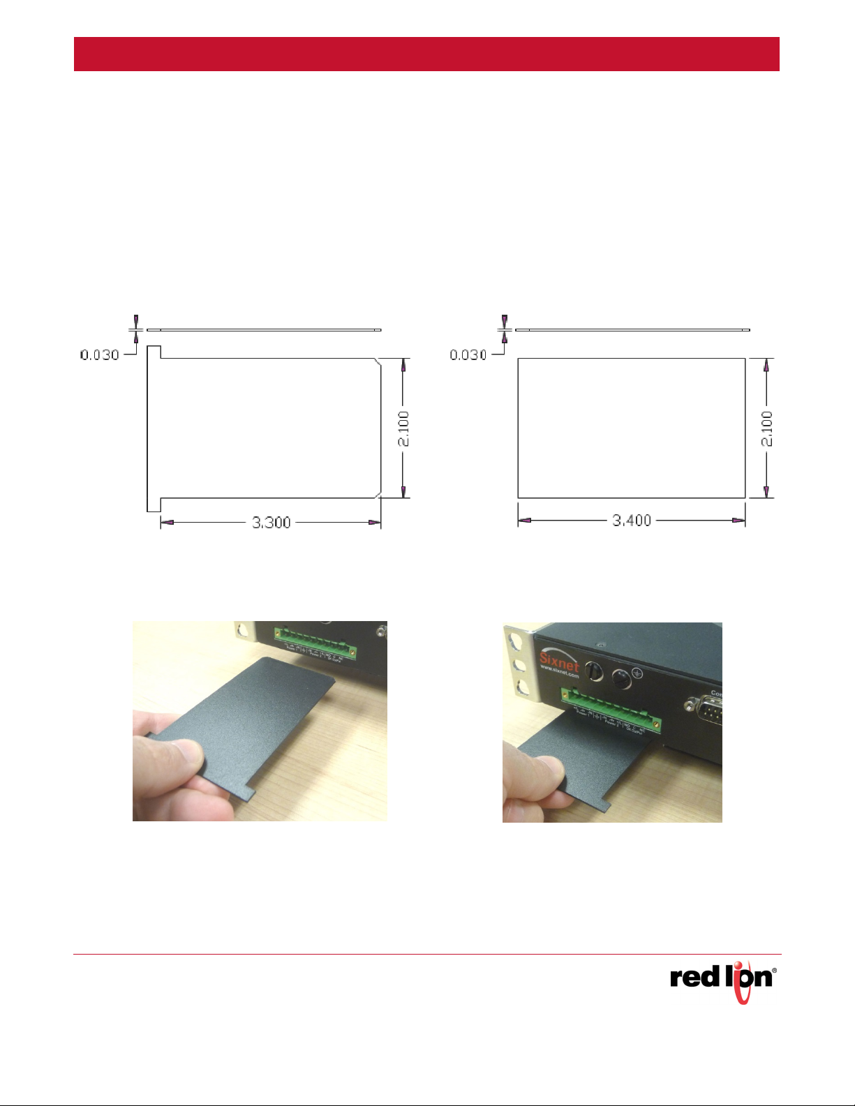
2. Acquire or make a hi-pot slot card. You can do this in several ways as follows:
a. Contact Red Lion and ask to be sent a complimentary “hi-pot slot card”.
b. Use a credit-card-sized plastic card (without raised lettering so not an actual credit card), laminated busi-
ness card or other similar plastic card. The dimensions should be as shown in the step 2 figure.
c. Cut out a card from 0.02” to 0.03” plastic (such as ABS or polycarbonate). The dimensions should be as
shown in the step 2 figure.
Hi-Pot Card
from Red Lion
3. Insert the card into the slot as shown in the images below. You may need to angle the card up a little to get it
started. Once it is started then push the card into the slot perpendicular to the face of the switch. As you push
the card in, about half way you should feel some resistance, this is normal. Push the card in until it either
stops or there is only about ¼” left sticking out. See images below.
Credit Card or
Laminated
Business Card
Sixnet Series EL326 Switch Hardware Guide 32
Page 45

Hi-Pot Testing and Maintenance Revised 2015-08-05
Card Fully
Inserted
4. With the card in place you can now perform the hi-pot (dielectric) test.
CAUTION: Make sure to remove the card when you are done testing. If you leave the
card in place during normal operations then your switch will not be fully protected from
surges.
Maintenance
The EL326 switch has no user serviceable parts. Any unauthorized service will void all warranties. In the unfortunate event that service is required please contact Red Lion for further instructions.
Service Information
We sincerely hope that you never experience a problem with any Red Lion product. If you do need service, call
Red Lion at 1-877-432-9908 for Technical Support. A trained specialist will help you to quickly determine the
source of the problem. Many problems are easily resolved with a single phone call. If it is necessary to return a unit
to us, an RO (Repair Order) can be obtained on the Red Lion website.
Red Lion tracks the flow of returned material with our RO system to ensure speedy service. You must include this
RO number on the outside of the box so that your return can be processed immediately.
Be sure to have your original purchase order number and date purchased available.
We suggest that you give us a repair purchase order number in case the repair is not covered under our warranty.
You will not be billed if the repair is covered under warranty.
Please supply us with as many details about the problem as you can. The information you supply will be written on
the RO form and supplied to the repair department before your unit arrives. This helps us to provide you with the
best service, in the fastest manner. Repairs are completed as soon as possible. If you need a quicker turnaround,
ship the unit to us by air freight. We give priority service to equipment that arrives by overnight delivery.
Sixnet Series EL326 Switch Hardware Guide 33
Page 46

Hi-Pot Testing and Maintenance Revised 2015-08-05
We apologize for any inconvenience that the need for repair may cause you. We hope that our rapid service meets
your needs. If you have any suggestions to help us improve our service, please give us a call. We appreciate your
ideas and will respond to them.
For Your Convenience:
Please fill in the following and keep this manual with your Red Lion system for future reference:
P.O. #:__________________ Date Purchased: ___________________
Purchased From:______________________________________________
To obtain support for Red Lion products:
Latest product info: http://www.redlion.net
Phone: 1-877-432-9908
Fax: 1-518-877-8346
E-mail: support@redlion.net
Address: Red Lion Controls • 20 Willow Springs Circle • York • PA • 17406 • USA
Sixnet Series EL326 Switch Hardware Guide 34
 Loading...