

Page 1

ENGLISH
RL-SPS33
P. O. Box 12010
Oklahoma City, OK 73157-2010
888.956.0000 • Fax: 405.228.1561
www.RedLionProducts.com
EN
ENGLISH
This instruction sheet provides you with the information required
to safely own and operate your product. Retain these instructions
for future reference.
The product you have purchased is of the highest quality
workmanship and material, and has been engineered to give you
long and reliable service. This product has been carefully tested,
inspected, and packaged to ensure safe delivery and operation.
Please examine your item(s) carefully to ensure that no damage
occurred during shipment. If damage has occurred, please contact the place of purchase. They will assist you in replacement or
repair, if required.
READ THESE INSTRUCTIONS CAREFULLY BEFORE
ATTEMPTING TO INSTALL, OPERATE, OR SERVICE
YOUR PRODUCT. KNOW THE PRODUCT’S APPLICATION,
LIMITATIONS, AND POTENTIAL HAZARDS. PROTECT
YOURSELF AND OTHERS BY OBSERVING ALL SAFETY
INFORMATION. FAILURE TO COMPLY WITH THESE
INSTRUCTIONS COULD RESULT IN PERSONAL INJURY
AND/OR PROPERTY DAMAGE!
DESCRIPTION
This unit is designed to pump wastewater from laundry trays,
washing machines, sinks, or dehumidifiers. It is not designed to
pump raw sewage, fluids other than water, or fluids with solids.
Inlet screen will remove many solids over 1/8” diameter, but large
amounts of solids can clog screen and result in pump failure.
Maximum fluid temperature is 125°F. Unit is designed to fit under
most sinks, so in many cases it is not necessary to recess the
unit into the floor.
ITEMS TO PURCHASE
NOTE: Some state or local codes require all electrical and/or
plumbing connections to be made by a licensed contractor. It is
the customer’s responsibility to determine codes involved and
to comply with these codes. If user can install unit, items to
purchase are:
1. Inlet piping, trap and union. (Basin cover has 1-1/2” FNPT fitting.)
2. Discharge piping with union. (Basin cover has 1-1/2” FNPT fitting.)
3. Vent piping with union. (Basin cover has 1-1/2” FNPT fitting.)
SAFETY GUIDELINES
1. CAUTION: To reduce the risk of electric shock, pull plug
before servicing this pump.
2. Read all instructions and safety guidelines thoroughly. Failure
to follow the guidelines and the instructions could result in
serious bodily injury and/or property damage.
3. Check local electrical and building codes before installation.
The installation must be in accordance with these regulations.
4. During normal operation the pump is immersed in water. Use
caution to prevent bodily injury when working near the pump:
a. Remove plug from the receptacle prior to touching, servic-
ing, or repairing the pump.
b. To minimize possible fatal electrical shock hazard, use
extreme care when changing fuses. Do not stand in water
while changing fuses or insert your finger into fuse socket.
Wastewater
Removal System
with RL-SP33V Pump
ELECTRICAL CONNECTIONS
All wiring must meet local codes, and a licensed electrical
contractor is recommended. The pump is supplied with a 3-prong
vented plug. Plugs must be plugged into a grounded receptacle
and vent tube must remain unobstructed for proper pump
operation. Pump should be on a separate circuit with fuse or
circuit breaker and ground fault circuit interrupter (GFCI). Be sure
electrical supply matches pump nameplate data. Do not use
extension cord. If installed in basement, plug connection should
be 4’ or more above floor, especially if basement floods. Be sure
electrical connections cannot be reached by rising water. Under
no circumstances should outlet box or receptacle be located
where it may become flooded or submerged by water.
INSTALLATION
All plumbing must meet local codes. A licensed plumbing
contractor is recommended. All fixtures connected to the SPXS33
Basin Kit must be vented according to state and local codes.
1. Assemble basin/pump.
2. Determine proper location for unit. Locate unit so that inlet
is gravity-fed. Unit will not draw water up from a lower level.
Position and level basin. Keep basin away from any item
that could puncture basin. Position selected should be convenient to inlet, discharge, and vent piping, and electrical supply.
3. Plumb inlet. Using 1-1/2” threaded pipe, plumb inlet to basin
cover fitting. Use a P-trap and a union next to the basin. Use
PTFE tape and hand tighten only on plastic fittings. Do not
reduce below 1-1/2” piping.
4. Plumb discharge. Using 1-1/2” threaded pipe, plumb
discharge to basin cover fitting. Use a swing check valve
no more than 3” from top of basin cover and a union.
Be sure discharge piping is sealed with PTFE tape and that
lift height of pump is not exceeded.
5. Plumb vent. Plumb vent using 2” threaded pipe to fitting in
basin cover. Use pipe joint compound on threads and hand
tighten only on plastic fittings. The basin must be vented in
accordance with state and local codes. The vent is essential for
proper switch operation and must not be omitted or restricted.
6. Test unit. Connect power cord to electrical supply as stated
in ELECTRICAL CONNECTIONS section. Secure power cord
to piping with ties or tape. Fill unit with water through inlet.
Pump should turn on with 7”–10” of water in tank, and turn off
when 1”–3” of water is left in tank.
MAINTENANCE
WARNING: Before performing any maintenance, shut off water
inlet and disconnect power cord from supply outlet. Pump may
become hot during operation. Allow pump to cool before servicing.
Basin Screen: Remove 4 1/4-20 screen cover plate screws, plastic
cover plate, seal ring, and screen. Clean inlet screen using a mild
detergent and water. Examine O-ring and if deformed, replace
with new O-ring. See replacement parts table.
Basin: Sediment may build up in basin causing pump to operate
improperly. Remove 10 1/4-20 screws from cover. Remove cord
grommet and loosen cords to allow slack and then remove cover.
Remove pump and clean basin using a mild detergent and water.
Reassemble in reverse order. Torque screws 18–20 in.-lbs.
If pump alignment plate is removed, it must be reinstalled per
pump alignment diagram.
Pump: Sediment or lint can clog pump and cause improper
operation. If necessary, remove pump and clean inlet screen,
using a mild detergent and water and reinstall. Plastic pump base
may also be removed to clean around impeller and inside base.
Remove the six base screws and clean base using a mild detergent and water. Do not remove impeller. When reinstalling base,
be sure seal ring is seated properly in groove and torque screws
to 10–15 in.-lbs. See pump manual for other information. For any
other pump repair, return the pump to a Little Giant authorized
service center.
1
Page 2
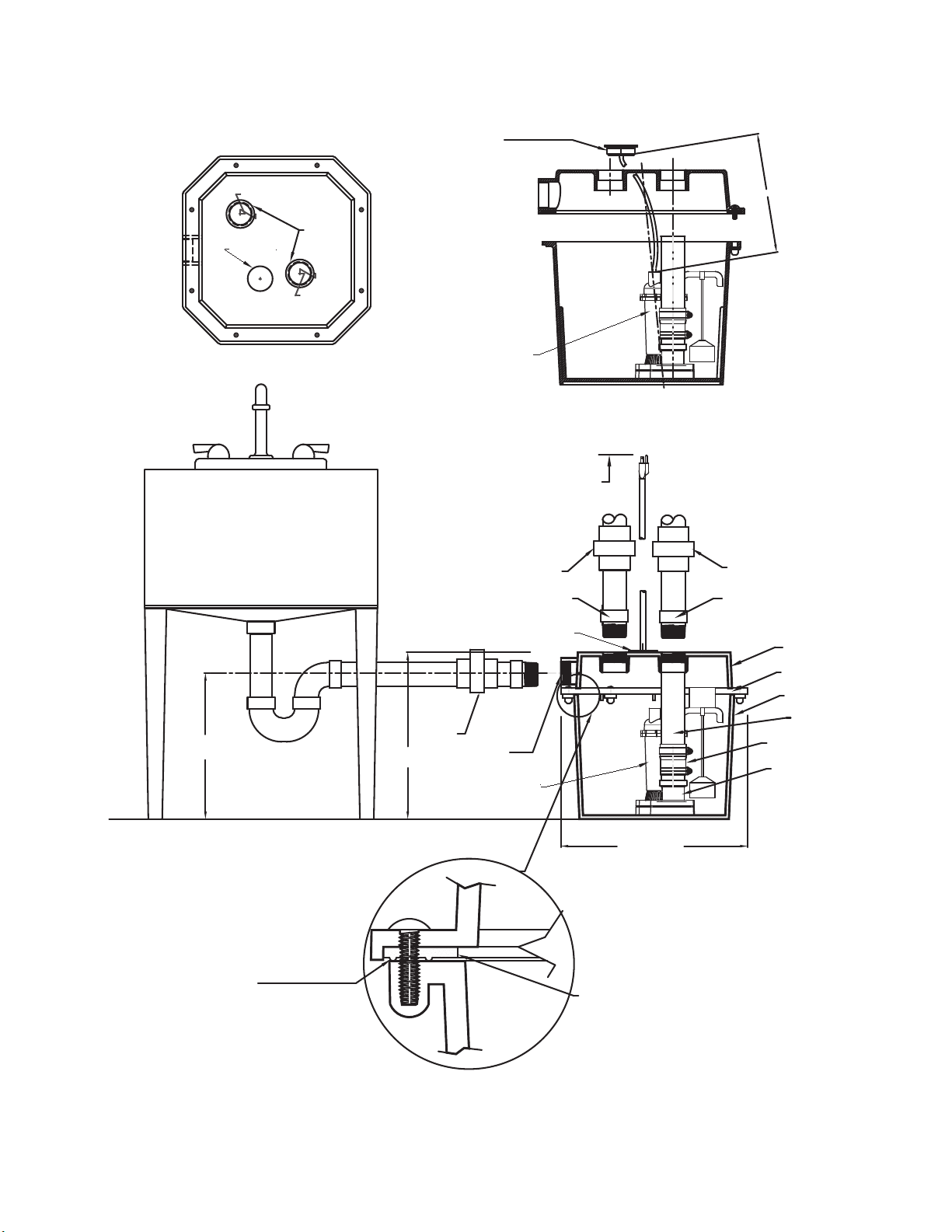
1, Turn Basin Lid over and "lay" in the seal as shown with ribs on seal up. From the bottom
side, through cover, insert (8) 1/4 inch screws through the holes in the seal.
2. Install check valve and discharge pipe into pump. Use Teon tape on the pipe threads.
Place pump in the basin and pull power cord through the power cord hole in the cover.
Allow approximately 12" of cord between pump and Power cord seal. Slip power cord seal
DISCHARGE
SOCKET
VENT
1
4
" Screws
Ribs on Seal
Facing Up
over pump power cable and install power cord seal into power cord hole in cover. Identify
opening for pump discharge pipe and be certain that discharge pipe is inserted into
socket in cover and that this is the discharge pipe and not the vent pipe. Install cover
and tighten bolts.
RE-USABLE SEAL
COVER
FIGURE 1 - TYPICAL INSTALLATION
COVER TOP VIEW
2.906
EITHER HOLE CAN
BE USED AS VENT
2.906
OR DISCHARGE.
SMOOTH
NO
THREADS
POWER
CORD
HOLE
1-1/2"
FNPT
THREADED
1.866
1.866
Power Cord Seal
Automatic
Sump Pump
12.00
11.56
A-N301
* ALL ITEMS OUTSIDE OF BASIN MUST BE CUSTOMER SUPPLIED
BASIN COVER/SEAL DETAIL
POWER CORD SEAL INCLUDED
* UNION
INLET OF BASIN
13.38
IS 1-1/2" FNPT.
AUTOMATIC SUMP PUMP
8 FT. POWER CORD
FROM PUMP BODY
* 1-1/2" UNION
* VENT OF BASIN
IS 1-1/2" FNPT.
VENT PIPING
15.125
DISCHARGE PIPING
* 1-1/2" UNION
* DISCHARGE OF BASIN IS
1-1/2" FNPT.
BASIN COVER
REUSABLE SEAL
BASIN
1-1/2" DISCHARGE PIPE
CHECK VALVE
ASSEMBLY
PUMP DISCHARGE IS
1-1/2" FNPT
RIBS OF SEAL RING
TOWARD BASIN
RE-USABLE SEAL RING
2
Page 3

LIMITED WARRANTY
For warranty consideration, the Red Lion brand (hereafter
“the Brand”) warrants that the products specified in this warranty are free from defects in material or workmanship of
the Brand. During the time periods and subject to the terms
and conditions hereinafter set forth, the Brand will repair or
replace to the original user or consumer any portion of this
product which proves defective due to materials or workmanship of the Brand. At all times the Brand shall have and possess the sole right and option to determine whether to repair
or replace defective equipment, parts, or components. The
Brand has the option to inspect any product returned under
warranty to confirm that the warranty applies before repair or
replacement under warranty is approved. This warranty sets
forth the Brand’s sole obligation and purchaser’s exclusive
remedy for defective product. Return defective product to the
place of purchase for warranty consideration.
WARRANTY PERIOD - 24 months from date of purchase by the
user. (No warranty on brushes, impeller or cam on models with
brush-type motors and/or flex-vane impellers.) In the absence of
suitable proof of the purchase date, the effective period of this
warranty will begin on the product’s date of manufacture.
LABOR, ETC. COSTS: The Brand shall IN NO EVENT be responsible or liable for the cost of field labor or other charges incurred
by any customer in removing and/or affixing any product, part, or
component thereof.
PRODUCT IMPROVEMENTS: The Brand reserves the right
to change or improve its products or any portions thereof
without being obligated to provide such a change or improvement for units sold and/or shipped prior to such change or
improvement.
GENERAL TERMS AND CONDITIONS: This warranty shall
not apply to damage due to acts of God, normal wear and
tear, normal maintenance services and the parts used in connection with such service, lightning or conditions beyond the
control of the Brand, nor shall it apply to products which, in
the sole judgment of the Brand, have been subject to negligence, abuse, accident, misapplication, tampering, alteration;
nor due to improper installation, operation, maintenance or
storage; nor to excess of recommended maximums as set
forth in the instructions.
Warranty will be VOID if any of the following conditions are found:
1. Product is used for purposes other than those for which it was
designed and manufactured
2. Product not installed in accordance with applicable codes,
ordinances, and good trade practices
3. Product connected to voltage other than indicated on nameplate
4. Pump used to circulate anything other than fresh water at
approximately room temperature
5. Pump allowed to operate dry (fluid supply cut off)
6. Sealed motor housing opened or product dismantled by customer
7. Cord cut off to a length less than three feet
DISCLAIMER: Any oral statements about the product made by the
seller, the Brand, the representatives, or any other parties do not constitute warranties, shall not be relied upon by the user, and are not part
of the contract for sale. Seller’s and the Brand’s only obligation, and
buyer’s only remedy, shall be the replacement and/or repair by the
Brand of the product as described above. NEITHER SELLER NOR THE
BRAND SHALL BE LIABLE FOR ANY INJURY, LOSS OR DAMAGE,
DIRECT, INCIDENTAL OR CONSEQUENTIAL (INCLUDING, BUT
NOT LIMITED TO, INCIDENTAL OR CONSEQUENTIAL DAMAGES
FOR LOST PROFITS, LOST SALES, INJURY TO PERSON OR
PROPERTY, OR ANY OTHER INCIDENTAL OR CONSEQUENTIAL
LOSS), ARISING OUT OF THE USE OR THE INABILITY TO USE THE
PRODUCT, AND THE USER AGREES THAT NO OTHER REMEDY
SHALL BE AVAILABLE TO IT. Before using, the user shall determine
the suitability of the product for his intended use, and user assumes all
risk and liability whatsoever in connection therewith. THE WARRANTY
AND REMEDY DESCRIBED IN THIS LIMITED WARRANTY IS AN
EXCLUSIVE WARRANTY AND REMEDY AND IS IN LIEU OF ANY
OTHER WARRANTY OR REMEDY, EXPRESSED OR IMPLIED,
WHICH OTHER WARRANTIES AND REMEDIES ARE HEREBY
EXPRESSLY EXCLUDED, INCLUDING BUT NOT LIMITED TO ANY
IMPLIED WARRANTY OF MERCHANTABILITY OR FITNESS FOR A
PARTICULAR PURPOSE, TO THE EXTENT EITHER APPLIES TO A
PRODUCT SHALL BE LIMITED IN DURATION TO THE PERIODS OF
THE EXPRESSED WARRANTIES GIVEN ABOVE. Some states and
countries do not allow the exclusion or limitations on how long an implied
warranty lasts or the exclusion or limitation of incidental or consequential
damages, so the above exclusion or limitations may not apply to you.
This warranty gives you specific legal rights, and you may also have other
rights which vary from state to state and country to country.
Page 4

For technical assistance, parts, or repair,
please contact .....................................1.888.956.0000
Pour l’aide technique, des parties ou la réparation,
entrez s’il vous plaît en contact .......................1.888.956.0000
Para la ayuda técnica, partes o la reparación,
por favor póngase en contacto .......................1.888.956.0000
www.RedLionProducts.com
Form 998091 - 04/2012 Rev. 001
 Loading...