

Page 1
THERMOPLASTIC SUMP PUMPS
Owner’s Manual
Table of Contents
SAFETY INSTRUCTIONS - - - - - - - 2
Product Description - - - - - - - - - 4
Models - - - - - - - - - - - - - - - 4
Flow Rates - - - - - - - - - - - - - 4
Specifications - - - - - - - - - - - 4
Installation - - - - - - - - - - - - - - 5
Physical Installation - - - - - - - - 5
Electrical Connections - - - - - - - 7
Operation Testing - - - - - - - - - - 8
Maintenance - - - - - - - - - - - - - 9
Periodic Service - - - - - - - - - - 9
Troubleshooting - - - - - - - - - - 10
Replacement Parts - - - - - - - - - 11
Limited Warranty - - - - - - - - - - 12
redlionproducts.com
Page 2
SAFETY INSTRUCTIONS
Hazard Messages
SAFETY INSTRUCTIONS
Hazard Messages
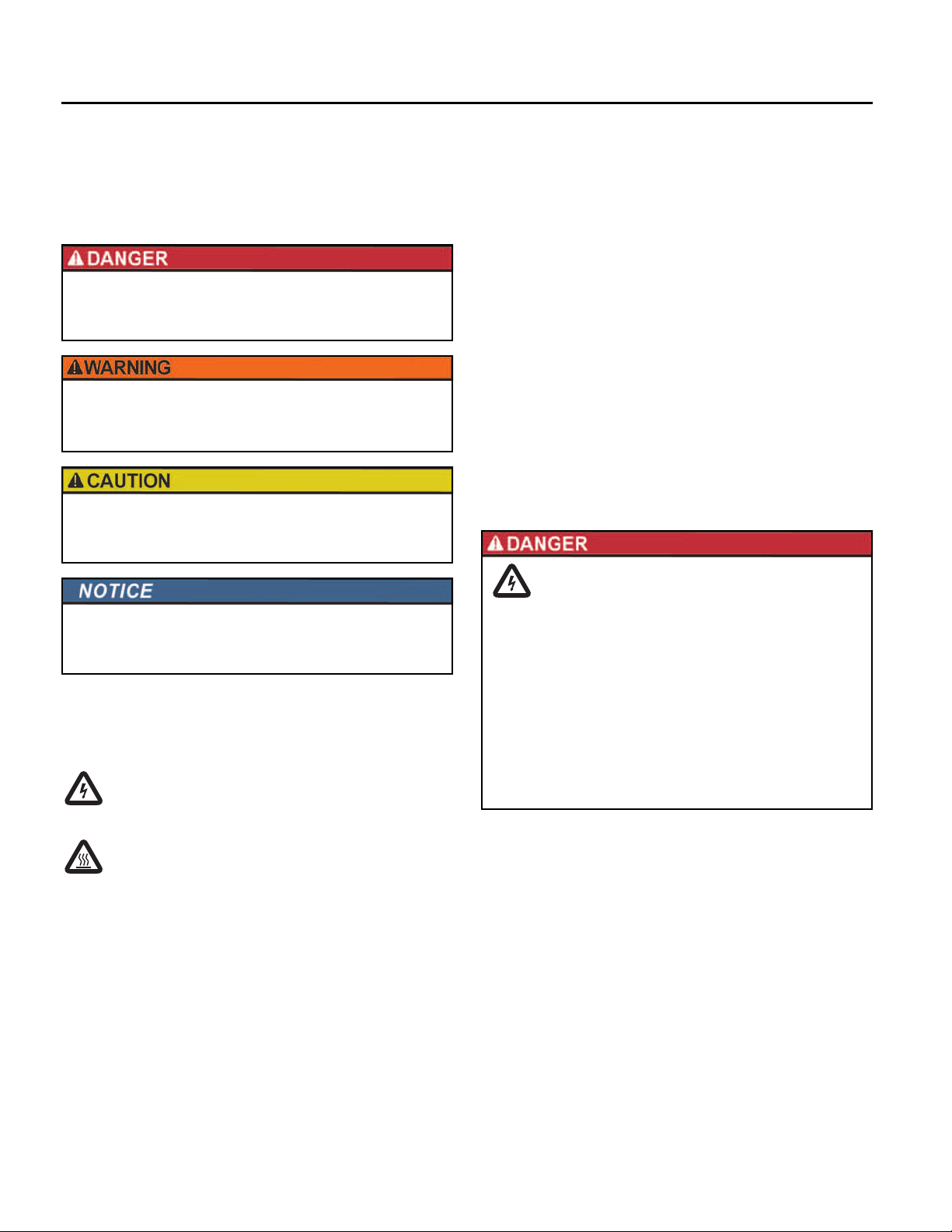
This manual includes safety precautions and other important
information in the following formats:
Indicates an imminently hazardous situation
which, if not avoided, will result in death or
serious injury.
Indicates a potentially hazardous situation
which, if not avoided, could result in death or
serious injury.
Indicates a potentially hazardous situation
which, if not avoided, could result in minor or
moderate personal injury.
Indicates a potentially hazardous situation
which, if not avoided could result in damage to
equipment or other property.
IMPORTANT: Identifies information that controls correct assem-
bly and operation of the product.
NOTE: Identifies helpful or clarifying information.
This symbol alerts the user to the presence of dangerous
voltage inside the product that might cause harm or electrical shock.
Before Getting Started
This equipment should be installed and serviced by technically
qualified personnel who are familiar with the correct selection
and use of appropriate tools, equipment, and procedures. Failure
to comply with national and local electrical and plumbing codes
and within Red Lion recommendations may result in electrical
shock or fire hazard, unsatisfactory performance, or equipment
failure.
Know the product’s application, limitations, and potential hazards. Read and follow instructions carefully to avoid injury and
operty damage. Do not disassemble or repair unit unless
pr
described in this manual.
Refer to product data plate(s) for additional precautions, operating instructions, and specifications.
Failure to follow installation or operation procedures and all
applicable codes may result in the following hazards:
Risk of death, personal injury, or
property damage due to explosion, fire,
or electric shock.
• Do not use to pump flammable or explosive fluids such as
gasoline, fuel oil, kerosene, etc.
• Do not use in explosive atmospheres or hazardous locations as classified by the NEC, ANSI/NFPA70.
• Do not handle a pump or pump motor with wet hands or
when standing on a wet or damp surface, or in water.
• When a pump is in its application, do not touch the motor,
pipes, or water until the unit is unplugged or electrically
disconnected.
2
This symbol alerts the user to the presence of hot surfaces that might cause fire or personal injury.
Page 3

SAFETY INSTRUCTIONS
Before Getting Started
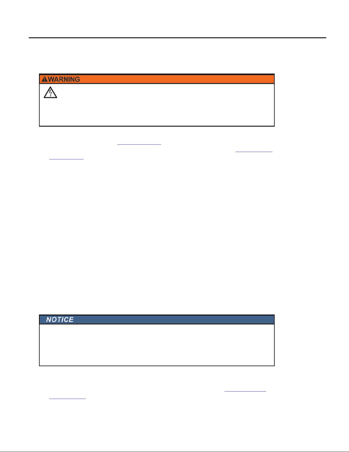
High voltages capable of causing severe
injury or death by electrical shock are
present in this unit.
• To reduce risk of electrical shock, disconnect power before
working on or around the system. More than one disconnect switch may be required to de-energize the equipment
before servicing.
• Be certain that this pump is connected to a circuit
equipped with a ground fault circuit interrupter (GFCI)
device if required by code.
• Wire pump system for correct voltages.
• The pump has been evaluated for use with water only.
Pump should only be used with liquids compatible with
pump component materials. If the pump is used with liquids incompatible with the pump components, the liquid
can cause failure to the electrical insulation system resulting in electrical shock.
Risk of damage to pump or other equipment.
• Do not use this pump for pumping sea water, beverages,
acids, chemical solutions, or any other liquid that promotes corrosion as this can result in damage to the pump.
• Do not run pump dry. For optimal cooling and to prolong
the motor life, the liquid level being pumped should normally be above the top of the pump housing.
• This pump is not suitable for pond applications.
Risk of bodily injury, electric shock,
or property damage.
• This equipment must not be used by children or persons
with reduced physical, sensory, or mental abilities, or lacking in experience and expertise, unless supervised or
instructed. Children may not use the equipment, nor may
they play with the unit or in the immediate vicinity.
• Do not use this pump for pumping any liquid intended for
human consumption.
• Equipment can start automatically. Always unplug the
pump power cord and disconnect the electrical power
before servicing the pump or switch. Lockout-Tagout
before servicing equipment.
• An inoperative or malfunctioning pump could lead to
flooding, resulting in personal injury or property damage.
• In applications where property damage and/or personal
injury might result from an inoperative or leaking pump
due to power outages, discharge line blockage, or any
other reason, an automatic back-up system and/or an
alarm should be installed.
• Do not run the pump dry. If run dry, the surface temperature of the pump will rise to a high temperature that could
cause skin burns if touched, and will cause serious damage to the pump.
• Do not oil the motor. The pump’s motor housing is sealed,
and contains a high-grade dielectric oil for heat transfer
and lifetime lubrication. Use of other oils could cause serious electric shock and/or permanent damage to the
pump.
• Operation of this equipment requires detailed installation
and operation instructions provided in this manual for use
with this product.
• Read entire manual before starting installation and operation.
• End User should receive and retain manual for future use.
• Keep safety labels clean and in good condition.
• Keep work area clean, well-lit, and uncluttered.
• Wear safety glasses while installing or performing maintenance on the pump.
• Do not wear loose clothing, jewelry, or anything that may
be caught in the rotating parts. Tie up long hair and
remove jewelry.
3
Page 4

PRODUCT DESCRIPTION
Models
PRODUCT DESCRIPTION
This submersible pump is for use in basins or lift stations and is suitable for pumping clear water and other
non-explosive, non-corrosive liquids. Do not use the pump in applications where sewage or any other debris
(gravel, sand, floating debris, etc.), abrasives, or corrosives are present.
These products have been carefully tested, inspected, and packaged to ensure safe delivery and operation.
Please examine your pump carefully to ensure that no damage occurred during shipment. If damage has
occurred, please contact the place of purchase. They will assist you in replacement or repair, if required.
The pump motor is equipped with an automatic resetting thermal protector, and may restart unexpectedly.
Thermal Protector tripping is an indication of motor overloading or overheating, which can be caused by
application issues such as an obstructed pump impeller, float stuck in the ON position, pump running dry,
pump air-locked, pump short cycling, excessively high or low voltage supply, or possibly a pump, motor,
bearings, or seal that have reached the end of their useful life.
Models
Model HP Amps Voltage Float Type On/Off Levels Minimum Basin Diameter
RL-SP25T 1/4 6 115 Tethered 14.5” (368 mm)/5.5” (140 mm) 14” (356 mm)
RL-SP33T 1/3 4.4 115 Tethered 14.5” (368 mm)/5.5” (140 mm) 14” (356 mm)
RL-SP33V 1/3 4.4 115 Vertical 7.25” (184 mm)/2.75” (70 mm) 11” (279 mm)
RL-SP50T 1/2 5 115 Tethered 14” (356 mm)/6” (152 mm) 14” (356 mm)
RL-SP50V 1/2 5 115 Vertical 7.25” (184 mm)/2.75” (70 mm) 11” (279 mm)
Flow Rates
Gallons/Liters per Hour
At Height: (Head) 5 ft (1.5 m) 10 ft (3 m) 15 ft (4.5 m) Shut Off
RL-SP25T 2640 / 9993 2100 / 7949 1560 / 5905 23 ft (7 m)
RL-SP33T 2880 / 10,902 2340 / 8858 1680 / 6359 25 ft (7.6 m)
RL-SP33V 2880 / 10,902 2340 / 8858 1680 / 6359 25 ft (7.6 m)
RL-SP50T 3060 / 11,583 2520 / 9539 1920 / 7268 28 ft (8.5 m)
RL-SP50V 3060 / 11,583 2520 /9539 1920 / 7268 28 ft (8.5 m)
Specifications
Discharge Size 1-1/2" FNPT
Intake Size 1/8" (3.2 mm) screened opening
Pump Housing Thermoplastic (including volute and screen)
Impeller Vortex design
Motor Single phase PSC with automatic reset thermal overload protection
Hardware 300 series stainless steel
Bearings Ball bearings
Pump Shaft Seal Mechanical, spring-loaded, stationary carbon with Nitrile boot and rotating ceramic seat
The motor housing contains oil to cool the motor and to lubricate the bearings and seals. These pumps can
Cooling
be operated with the motor housing partially exposed for extended periods of time. However, for the best
cooling and longest motor life, the liquid level being pumped should normally be above the top of the
pump housing.
4
Page 5
INSTALLATION
Physical Installation
Risk of severe injury or death by electrical shock.
• Always disconnect the electrical power before touching the pump or discharge.
• Check local electrical and building codes before installation. The installation must be in accordance
with their regulations as well as the most recent National Electrical Code (NEC).
1. Pump must be installed in a suitable basin that is at least 18” (457 mm) deep, and in accordance with
local plumbing codes. Refer to
2. Clean any debris from the basin and set the pump in the center of the basin (refer to “Typical Installa-
tion” on page 6).
3. The pump must be placed on a hard, level surface. Never place the pump directly on clay, earth or
gravel surfaces. These surfaces contain small stones, gravel, sand etc. that may clog or damage the
pump and cause pump failure.
4. Do not attempt to restrict the intake side of these pumps. Restricting the intake may cause damage to
the seal and may starve the pump. If you require reduced flow rates, place a valve on the discharge side
of the pump. Or, if flexible vinyl tubing is used, a clamp can be used on the tubing to restrict the flow.
5. Connect discharge piping. Use pipe joint compound at all connections. Sump pumps can be piped to
discharge into the house drainage system, to a dry well, splash block, or to a storm drain, depending on
local plumbing codes. The discharge pipe should be as short as possible and contain as few elbows as
possible. The discharge pipe should be the same diameter, or larger than, the pump discharge size. A
smaller pipe will restrict capacity and reduce pump performance. The pump comes with a 1-1/2" FNPT
discharge and a 1-1/4” FNPT reducing bushing.
• Support the pump and piping while assembling and when installed. Failure to do so may cause the
piping to break, the pump to fail, motor bearing failures, etc.
• Always install a union in the discharge line just above the basin cover to allow for easy removal of
the pump for cleaning or repair.
6. A full flow check valve must be used in the discharge line to prevent back-flow of liquid into the basin.
A missing, improperly installed, or malfunctioning check valve can cause a pump to short-cycle due to
back-flow of the pumped fluid from the discharge plumbing back into the basin, significantly shorten
ing the life of the pump.
“Models” on page 4 for minimum basin diameters.
INSTALLATION
Physical Installation
-
Risk of property damage due to flooding.
• When a check valve is used, drill a relief hole 1/8 – 3/16" (3.2 – 4.8 mm) in diameter in the discharge
pipe. This hole should be located below the floor line between the pump discharge and the check
valve. Unless such a relief hole is provided, the pump could “air lock” and will not pump water even
though it will run.
7. Tape the pump and switch cords to the discharge pipe with electrical tape to keep the power cords
securely routed away from the pump inlet and any control floats.
8. Connect the pump to an appropriate power supply following the instructions in “Electrical Connec-
tions” on page 7.
5
Page 6

INSTALLATION
Physical Installation
9. Test the operation of the pump system by following the instructions in “Operation Testing” on page 8 of
this manual. Do not attempt to operate the pump without water; this will damage the seals and bearings and could result in permanent damage to the pump.
10. Place cover over basin. This cover will help prevent debris from entering the pit and will guard against
accidental injury.
Typical Installation
I
SEPARATE PROTECTED AND GROUNDED SERVICE OUTLET, 4’ FROM FLOOR MINIMUM
FLOAT SWITCH POWER CORD
PUMP POWER CORD
GATE VALVE
GAS-TIGHT BASIN PER MINIMUM ON PAGE 4
3/16” (4.8 mm) AIR BLEED HOLE IN DISCHARGE PIPE
PLACE PUMP ON HARD, LEVEL SURFACE.
NEVER PLACE DIRECTLY ON CLAY,
EARTH, OR GRAVEL SURFACE
CHECK VALVE
DISCHARGE PIPE NO SMALLER
THAN PUMP OUTLET
2” OR 3” VENT PIPE
(51 OR 76 mm)
BASIN COVER
O
TETHER LENGTH:
3-1/2” (89 mm)
VERTICAL FLOAT
SWITCH
(See Page 4)
6
Page 7

Electrical Connections
Risk of severe injury or death by electrical shock.
• Always disconnect the electrical power before touching the pump or discharge.
• Pumps are supplied with a grounding conductor and grounding-type attachment plug. To reduce
risk of electric shock, be certain that it is connected only to a properly grounded grounding-type
receptacle. Do not remove the third prong from the plug. The third prong is to ground the pump to
help prevent possible electric shock hazard.
• Check electrical outlets with a circuit analyzer to ensure power, neutral, and ground wires are properly connected. If not, a qualified, licensed electrician should correct the problem.
• Do not use the power cord for lifting the pump.
• Do not remove the third prong from the plug, or cut plug from cord. These actions will void the warranty.
• Do not use an extension cord.
Wiring Guidelines
INSTALLATION
Electrical Connections
Check the pump label for proper voltage required. Do not connect to voltage other than that shown.
Be certain that this pump is connected to a circuit equipped with a ground fault circuit interrupter (GFCI)
de
vice if required by code.
The pump should be connected or wired to its own circuit, with no other electric receptacles or equipment
in the cir
• RL-SP Series breaker size = 15 A
cuit. The fuses or circuit breaker should be of ample capacity in the electrical circuit.
Power Supply
Automatic Pump Operation
Pumps with a tethered or vertical float switch include two power cords with a piggyback
plug on the switch cord. For automatic operation, plug the pump cord into the piggyback
switch cord. Plug the switch cord (with pump cord attached) into a GFCI outlet.
Manual Pump Operation
For manual operation, disconnect the pump cord from the float switch piggyback plug.
Plug the pump cord directly into a dedicated GFCI receptacle.
Manual, continuous pump operation should be used only for emergencies, or when a
lar
ge volume of water is to be pumped.
The pump must be continuously monitored during manual operation and disconnected from power before
the pump runs dry
. If the pump is run dry, it may damage the pump and void the warranty.
7
Page 8

OPERATION TESTING
Testing Pump Operation
OPERATION TESTING
Risk of damage to pump or other equipment.
• Do not attempt to run the pump without water; this could result in permanent damage to the pump.
• If pump is run dry, it may damage pump and void the warranty.
If the pump does not operate properly, refer to “Troubleshooting” on page 10. If the solution still cannot be
found, please contact the place of purchase or Technical Support at 888-885-9254.
Do not let the unit run dry (without liquid). It is designed to be cooled by pumping fluid. The seal may be
damaged and the mot
or may fail if the pump is allowed to run dry.
If the unit is going to be idle for a period of time, follow the cleaning instructions in
Volute” on page 9. Do not let the unit freeze. This may cause cracking or distortion that may destroy the
unit.
“Cleaning Impeller and
Testing Pump Operation
Pumps are equipped with a tethered or vertical float switch that operate by floating on top of accumulating
water. Rising water in the basin lifts the float, which activates the switch, turning on the pump. As the water
level falls, the float lowers until the switch deactivates, turning off the pump.
When the pump is installed in a basin with a sealed cover, pump operation cannot be observed. The basin
cover will usually have a spare hole that is plugged with a rubber plug. This plug can be removed and pump
operation can be observed.
To test system operation, follow these steps:
1. Connect the float switch and pump to an appropriate power supply with voltage consistent with the
pump v
oltage, as indicated on the pump nameplate.
2. If there is a gate valve on the discharge line, be sure the valve is open.
3. Run water into the basin until the pump is activated. Do not attempt to run the pump without water;
ould result in permanent damage to the pump.
this c
4. Confirm that the pump and its float switch are functioning as intended.
NOTE: If the pump doesn’t turn on, test manual operation by connecting the pump’s power plug
directly into the power source. If the pump runs, test the float switch.
5. Confirm that the ON/OFF levels are within specifica
exist that could inhibit switch operation.
6. Confirm that there are no leaks in the pump discharge plumbing and main home drain pipe plumbing.
7. Allow the pump to operate through several on/off cycles.
tion, and confirm that no potential obstructions
Testing the Float Switch
A float switch can be bench tested by using an ohmmeter to check for
continuity between the incoming and outgoing connections of the piggyback plug while raising and lowering the float.
8
Page 9

MAINTENANCE
Risk of severe injury or death by electrical shock, high
temperatures, or pressurized fluids.
• Always unplug the pump power cord and disconnect the electrical power before servicing the pump
or switch.
• Let pump cool for a minimum of 2 hours before attempting to service. Submersible pumps contain
oil that becomes pressurized and hot under normal operating conditions.
Risk of damage to pump or other equipment.
• This unit is permanently lubricated. Oiling is not required. Do not open the sealed portion of the unit
or remove housing screws.
• Do not remove the motor housing cover.
• Do not remove the impeller
• Warranty is void if the motor housing cover, impeller, or seals have been removed. Repairs on the
motor or impeller require special tools.
MAINTENANCE
Periodic Service
Periodic Service
Inspect and test the pump system condition and operation every three months—more frequently in heavy
use applications.
1. Check the power cords, electric receptacle, and/or junction box for damage or corrosion. The power
cord on these units cannot be replaced. If damaged, replace the pump.
2. Remove all debris (gravel, sand, floating debris, etc.) from the basin.
3. Check the pump system components (basin, pump, switch, etc.) for any build-up (sludge, sediment,
minerals, etc.) that would inhibit functionality of the components. If significant, remove build-up or
replace affected components.
4. Confirm that all flexible coupling hose clamps are fully engaged with plumbing and fully tightened.
5. Test operation of the pump system. Refer to “Operation Testing” on page 8.
6. While the pump is running, make sure a stream of water is escaping from the air bleed hole. If not, clear
the hole of any deposits or debris.
Cleaning Impeller and Volute
Periodic cleaning of the pump parts will prolong the life and efficiency of the pump.
After removing power to the pump, disconnect the pump from the discharge plumbing.
1. Remove the screws that hold the base to the volute, then separate the base from the volute.
2. Remove the base and clean the impeller and the volute passage. Do not use strong solvents on the
impeller.
3. Be sure the impeller turns freely after cleaning.
4. Attach the base to the volute, making sure the seal is properly aligned.
9
Page 10

MAINTENANCE
Troubleshooting
Troubleshooting
Problem Probable Causes Corrective Action
Pump does not turn on
Pump will not shut off
Pump runs but does not
discharge liquid
Pump does not deliver
rated capacity
Pump cycles continuously
Pump not connected to electrical power. Connect pump to a dedicated circuit equipped with GFCI.
Circuit breaker off or fuse removed. Turn on circuit breaker or replace fuse.
For models equipped with tethered float
switch: Accumulation of trash or buildup on float.
For models equipped with tethered float
switch: Float obstruction.
Defective switch. Replace switch.
Defective motor. Replace pump.
Float obstruction. Check float path and provide clearance.
Pump is air locked due to missing or
clogged air relief hole.
Liquid inflow matches pump capacity. Larger pump required.
Defective switch. Replace switch.
Check valve installed backwards. Check flow indicating arrow on check valve body to ensure
Check valve stuck or plugged. Remove check valve and inspect for proper operation.
Lift too high for pump. Check rated pump performance.
Inlet to impeller plugged. Pull pump and clean.
Pump is air locked due to missing or
clogged air relief hole.
Lift too high for pump. Check rated pump performance.
Low voltage, speed too slow. Check that supply voltage matches the nameplate rating.
Impeller or discharge pipe is clogged. Pull pump and clean. Check pipe for scale or corrosion.
Impeller wear due to abrasives. Replace pump.
No check valve in long discharge pipe
allowing liquid to drain back into basin.
Check valve leaking. Inspect check valve for correct operation.
Basin too small for inflow. Install larger basin.
Clean float.
Check float path and provide clearance.
If missing, drill an air relief hole as described in
lation” on page 5. If clogged, clean obstruction from air relief.
proper installation.
If missing, drill an air relief hole as described in INSTALLATION.
If clogged, clean obstruction from air relief hole.
Install a check valve in discharge line.
“Physical Instal-
10
Page 11

Replacement Parts
Part Number Description
640171 Tethered Float Switch, Piggyback, 10 ft (3 m)
640172 Tethered Float Switch, Piggyback, 20 ft (6.1 m)
14942904 Vertical Float Switch, Piggyback, 10 ft (3 m)
MAINTENANCE
Replacement Parts
11
Page 12

LIMITED WARRANTY
THIS WARRANTY (“WARRANTY”) SETS FORTH THE BRAND’S SOLE OBLIGATION AND PURCHASER’S EXCLUSIVE REMEDY FOR DEFECTIVE
PRODUCT.
The Red Lion® Brand (the “Brand”) warrants that the products accompanied by this Warranty are free from defects in materials or workmanship that
exist at the time of sale by the Brand and which occur or exist within the applicable warranty period identified below. Any distributor, sub-distributor,
recipient, end-user and/or consumer agrees that by accepting the receipt of the products, the distributor, sub-distributor, recipient, end user and/or
consumer expressly agrees to be bound by the terms of this Warranty.
I. Applicable Warranty Period
The products accompanied by this Warranty shall be covered by this Warranty for a period of 24 months from the date of original purchase by the
consumer. In the absence of suitable proof of purchase date, the warranty period of this product will begin to run on the product's date of
manufacture.
II. Instructions Applicable to this Limited Warranty
1. Consumers wishing to submit a warranty claim must return the products accompanied by this Warranty to the point of purchase for warranty consideration.
2. Upon discovery of a defect, any personal injury, property damage or any other type of resulting damage, if applicable, shall be reasonably
mitigated to the extent possible.
3. At its discretion, the Brand may inspect products either at its facilities or in the field, and after determination of a warranty claim, will, at its
option, repair or replace defective parts. Repaired or replaced parts will be returned freight prepaid by the Company.
4. This Warranty does not cover any labor or shipping charges. The Brand shall not be liable for any costs or charges attributable to any product testing, maintenance, installation, repair or removal, or for any tools, supplies, or equipment needed to install, repair, or remove any
product.
III. Limitations Applicable to this Limited Warranty
THIS WARRANTY DOES NOT APPLY TO ANY OF THE FOLLOWING:
1. Brushes, impeller or cam on models with brush-type motors and/or flex-vane impellers.
2. Any product that is not installed, applied, maintained, and used in accordance with the Brand's published instructions, applicable codes,
applicable ordinances and/or with generally accepted industry standards.
3. Any product that has been subject to misuse, misapplication, neglect, alteration, accident, abuse, tampering, acts of God (including lightning), acts of terrorism, acts of war, fire, improper storage or installation, improper use, improper maintenance or repair, damage or casualty, or to an excess of the recommended maximums as set forth in the product instructions.
4. Any product that is operated with any accessory, equipment, component, or part not specifically approved by the Brand.
5. Use of replacement parts not sold by the Brand, the unauthorized addition of non- Brand products to other Brand products, and the unauthorized alteration of Brand products.
6. Products damaged by normal wear and tear, normal maintenance services and the parts used in connection with such service, or any other
conditions beyond the control of the Brand.
7. Any product that has been used for purposes other than those for which it was designed and manufactured.
8. Any use of the product where installation instructions and/or instructions for use were not followed.
9. Products connected to voltage other than indicated on nameplate.
10. Products where the pump was exposed to any of the following: sand, gravel, cement, grease, plaster, mud, tar, hydrocarbons, hydrocarbon
derivatives (oil, gasoline, solvents, etc.) or other abrasive or corrosive substances.
11. Products in which the pump has been used to pump or circulate anything other than fresh water at room temperature.
12. Products in which the pump was allowed to operate dry (fluid supply cut off).
13. Products in which the sealed motor housing has been opened or the product has been otherwise dismantled by customer.
14. Products in which the cord has been cut to a length of less than three feet.
12
Page 13

The Brand reserves the right at any time, and from time to time, to make changes in the design and/or improvements upon its product without
thereby imposing any obligation upon itself to make corresponding changes or improvements in or upon its products already manufactured and/or
previously sold. The Brand further reserves the right to substitute parts or components of substantially equal quality in any warranty service required
by operation of this Warranty.
This Warranty is the entire warranty authorized and offered by the Brand. There are no warranties or representations beyond those expressed in this
document.
THIS WARRANTY AND REMEDY IS IN LIEU OF ALL OTHER WARRANTIES AND REMEDIES INCLUDING WITHOUT LIMITATION, WARRANTIES OF MERCHANTABILITY AND/OR FITNESS FOR A PARTICULAR PURPOSE, WHICH ARE HEREBY SPECIFICALLY DISCLAIMED AND EXPRESSLY EXCLUDED.
CORRECTION OF NON-CONFORMITIES, IN THE MANNER AND FOR THE PERIOD OF TIME AS SET FORTH ABOVE, SHALL CONSTITUTE FULFILLMENT
OF ALL LIABILITY OF THE BRAND TO THE PURCHASER WHETHER BASED ON CONTRACT, NEGLIGENCE, OR OTHERWISE.
THE BRAND SHALL NOT BE LIABLE FOR INCIDENTAL, CONSEQUENTIAL OR SPECIAL DAMAGES SUCH AS, BUT NOT LIMITED TO:
DAMAGE TO OR LOSS OF OTHER PROPERTY OR EQUIPMENT, LOSS OF USE OF EQUIPMENT, FACILITIES OR SERVICE, LOSS OF PROFIT OR SALES,
COST OF PURCHASES OR REPLACEMENT GOODS, CLAIMS OF CUSTOMERS OF THE PURCHASER, FAILURE TO WARN AND/OR INSTRUCT, LOSS OF
OTHER PRODUCTS, OR COSTS OF ENVIRONMENTAL REMEDIATION, OR DIMINUTION IN PROPERTY VALUE. THE REMEDIES OF THE PURCHASER
SET FORTH HEREIN ARE EXCLUSIVE, AND THE LIABILITY OF THE BRAND SHALL NOT, EXCEPT AS EXPRESSLY PROVIDED HEREIN, EXCEED THE
PRICE OF THE PRODUCTS UPON WHICH SUCH LIABILITY IS BASED. DAMAGES AS SET FORTH IN THIS PARAGRAPH SHALL BE REASONABLY MITIGATED TO THE EXTENT POSSIBLE. THIS PARAGRAPH SHALL ALSO APPLY TO ALL DAMAGES RESULTING FROM CONDITIONS SET FORTH IN SECTION III ABOVE AND (1) DEFECTS IN PRODUCT PROTOTYPES OR REPLACEMENT PART PROTOTYPES THAT HAVE NOT BEEN PUT INTO
PRODUCTION, CIRCULATED AND SOLD BY THE BRAND, AND/OR (2) DEFECTS THAT WERE NOT FOUND AT THE TIME OF SALE DUE TO SCIENTIFIC
AND TECHNOLOGICAL REASONS.
This Warranty gives you specific legal rights. You may have other rights, which vary according to the applicable laws and regulations. Where
any term of this warranty is prohibited by such laws, it shall be null and void, but the remainder of this Warranty shall remain in full force and
effect.
DISCLAIMER: Any oral statements about the product made by the seller, the Brand, the representatives or any other parties, do not constitute warranties, shall not be relied upon by the user, and are not part of the contract for sale. Seller’s and the Brand’s only obligation, and buyer’s only remedy,
shall be the replacement and/or repair by the Brand of the product as described above. Before using, the user shall determine the suitability of the
product for his intended use, and user assumes all risk and liability whatsoever in connection therewith.
13
Page 14

For technical assistance, please contact:
888.885.9254 | redlionproducts.com
Form 998491 Rev. 002 04/19
 Loading...