

Page 1

Sixnet® Series
RAM® 9000
Cellular RTUs
Hardware Guide | July 2015
Page 2

Table of Contents Revised 2015-07-16
Preface . . . . . . . . . . . . . . . . . . . . . . . . . . . . . . . . . . . . . . . . . . . . . . . . . . . . . . . . . . . . . . . . .4
Disclaimer . . . . . . . . . . . . . . . . . . . . . . . . . . . . . . . . . . . . . . . . . . . . . . . . . . . . . . . . . . . . . . . . . . 4
Compliance Information . . . . . . . . . . . . . . . . . . . . . . . . . . . . . . . . . . . . . . . . . . . . . . . . . . . . . . 4
Trademark Acknowledgments . . . . . . . . . . . . . . . . . . . . . . . . . . . . . . . . . . . . . . . . . . . . . . . . . . 5
Release Notes and Document Updates. . . . . . . . . . . . . . . . . . . . . . . . . . . . . . . . . . . . . . . . . . . 5
Additional Product Information . . . . . . . . . . . . . . . . . . . . . . . . . . . . . . . . . . . . . . . . . . . . . . . . 6
Safety Information . . . . . . . . . . . . . . . . . . . . . . . . . . . . . . . . . . . . . . . . . . . . . . . . . . . . . . . . . . . 6
Warnings/Cautions/Notes . . . . . . . . . . . . . . . . . . . . . . . . . . . . . . . . . . . . . . . . . . . . . . . . . . . . . 6
Statement of Limited Warranty . . . . . . . . . . . . . . . . . . . . . . . . . . . . . . . . . . . . . . . . . . . . .8
Chapter 1 Product Overview. . . . . . . . . . . . . . . . . . . . . . . . . . . . . . . . . . . . . . . . . . .14
RAM 9000 Cellular RTU Product Highlight. . . . . . . . . . . . . . . . . . . . . . . . . . . . . . . . . . . . . . . . . . . . . 14
Specifications . . . . . . . . . . . . . . . . . . . . . . . . . . . . . . . . . . . . . . . . . . . . . . . . . . . . . . . . . . . . . . . . . . . . 15
General Specifications. . . . . . . . . . . . . . . . . . . . . . . . . . . . . . . . . . . . . . . . . . . . . . . . . . . . . . . . . . . . . . . . . . . . . . . . . . 15
RAM 9000 Model Comparison Chart . . . . . . . . . . . . . . . . . . . . . . . . . . . . . . . . . . . . . . . . . . . . . . . . . . . . . . . . . . . . . . 18
RAM 9000 Cellular RTU View . . . . . . . . . . . . . . . . . . . . . . . . . . . . . . . . . . . . . . . . . . . . . . . . . . . . . . . . . . . . . . . . . . . . 18
Power Specifications and Consumption. . . . . . . . . . . . . . . . . . . . . . . . . . . . . . . . . . . . . . . . . . . . . . . . . . . . . . . . . . . . 19
Electrical Specifications and Pinout . . . . . . . . . . . . . . . . . . . . . . . . . . . . . . . . . . . . . . . . . . . . . . . . . . . . . . . . . . . . . . . 19
Indicator Lights . . . . . . . . . . . . . . . . . . . . . . . . . . . . . . . . . . . . . . . . . . . . . . . . . . . . . . . . . . . . . . . . . . . . . . . . . . . . . . . 22
Bootup LED Sequence. . . . . . . . . . . . . . . . . . . . . . . . . . . . . . . . . . . . . . . . . . . . . . . . . . . . . . . . . . . . . . . . . . . . . . . . . . 23
Data Interface Specifications: Serial, Ethernet & USB. . . . . . . . . . . . . . . . . . . . . . . . . . . . . . . . . . . . . . . . . . . . . . . . . . 23
Mode/Reset Button functions . . . . . . . . . . . . . . . . . . . . . . . . . . . . . . . . . . . . . . . . . . . . . . . . . . . . . . . . . . . . . . . . . . . 25
Ordering Guide . . . . . . . . . . . . . . . . . . . . . . . . . . . . . . . . . . . . . . . . . . . . . . . . . . . . . . . . . . . . . . . . . . 27
Chapter 2 Hardware Installation . . . . . . . . . . . . . . . . . . . . . . . . . . . . . . . . . . . . . . .28
Mounting the RAM 9000 Cellular RTU . . . . . . . . . . . . . . . . . . . . . . . . . . . . . . . . . . . . . . . . . . . . . . . . 28
DIN Rail Mounting & Removal . . . . . . . . . . . . . . . . . . . . . . . . . . . . . . . . . . . . . . . . . . . . . . . . . . . . . . 28
Mechanical Dimension Diagrams . . . . . . . . . . . . . . . . . . . . . . . . . . . . . . . . . . . . . . . . . . . . . . . . . . . . 30
Antennas and Wireless . . . . . . . . . . . . . . . . . . . . . . . . . . . . . . . . . . . . . . . . . . . . . . . . . . . . . . . . . . . . 30
Cellular Antenna and Cable Specifications. . . . . . . . . . . . . . . . . . . . . . . . . . . . . . . . . . . . . . . . . . . . . . . . . . . . . . . . . . 31
GPS Antenna . . . . . . . . . . . . . . . . . . . . . . . . . . . . . . . . . . . . . . . . . . . . . . . . . . . . . . . . . . . . . . . . . . . . . . . . . . . . . . . . . 32
Installation and Verification. . . . . . . . . . . . . . . . . . . . . . . . . . . . . . . . . . . . . . . . . . . . . . . . . . . . . . . . . . . . . . . . . . . . . . 32
Wi-Fi Antenna . . . . . . . . . . . . . . . . . . . . . . . . . . . . . . . . . . . . . . . . . . . . . . . . . . . . . . . . . . . . . . . . . . . . . . . . . . . . . . . . 33
Ethernet cable . . . . . . . . . . . . . . . . . . . . . . . . . . . . . . . . . . . . . . . . . . . . . . . . . . . . . . . . . . . . . . . . . . . 33
RAM 9000 Series Hardware Guide 2
Page 3

Table of Contents Revised 2015-07-16
USB Device Cable. . . . . . . . . . . . . . . . . . . . . . . . . . . . . . . . . . . . . . . . . . . . . . . . . . . . . . . . . . . . . . . . . 34
USB Host Cable . . . . . . . . . . . . . . . . . . . . . . . . . . . . . . . . . . . . . . . . . . . . . . . . . . . . . . . . . . . . . . . . . . 34
Serial RS485 Wiring . . . . . . . . . . . . . . . . . . . . . . . . . . . . . . . . . . . . . . . . . . . . . . . . . . . . . . . . . . . . . . . 34
RS485 Wiring Diagram . . . . . . . . . . . . . . . . . . . . . . . . . . . . . . . . . . . . . . . . . . . . . . . . . . . . . . . . . . . . . . . . . . . . . . . . . 36
Serial RS232 Cable . . . . . . . . . . . . . . . . . . . . . . . . . . . . . . . . . . . . . . . . . . . . . . . . . . . . . . . . . . . . . . . . 36
Power Source. . . . . . . . . . . . . . . . . . . . . . . . . . . . . . . . . . . . . . . . . . . . . . . . . . . . . . . . . . . . . . . . . . . . 37
Powering the unit . . . . . . . . . . . . . . . . . . . . . . . . . . . . . . . . . . . . . . . . . . . . . . . . . . . . . . . . . . . . . . . . . . . . . . . . . . . . . 37
Testing the power connection . . . . . . . . . . . . . . . . . . . . . . . . . . . . . . . . . . . . . . . . . . . . . . . . . . . . . . . . . . . . . . . . . . . 37
6-pin Screw Terminal. . . . . . . . . . . . . . . . . . . . . . . . . . . . . . . . . . . . . . . . . . . . . . . . . . . . . . . . . . . . . . . . . . . . . . . . . . . 37
Power Input Diagram . . . . . . . . . . . . . . . . . . . . . . . . . . . . . . . . . . . . . . . . . . . . . . . . . . . . . . . . . . . . . . . . . . . . . . . . . . 38
Battery . . . . . . . . . . . . . . . . . . . . . . . . . . . . . . . . . . . . . . . . . . . . . . . . . . . . . . . . . . . . . . . . . . . . . . . . . 38
Battery Removal and Installation . . . . . . . . . . . . . . . . . . . . . . . . . . . . . . . . . . . . . . . . . . . . . . . . . . . . . . . . . . . . . . . . . 39
SIM Cards . . . . . . . . . . . . . . . . . . . . . . . . . . . . . . . . . . . . . . . . . . . . . . . . . . . . . . . . . . . . . . . . . . . . . . . 40
SD Card . . . . . . . . . . . . . . . . . . . . . . . . . . . . . . . . . . . . . . . . . . . . . . . . . . . . . . . . . . . . . . . . . . . . . . . . . 41
I/O Wiring . . . . . . . . . . . . . . . . . . . . . . . . . . . . . . . . . . . . . . . . . . . . . . . . . . . . . . . . . . . . . . . . . . . . . . 41
I/O Wiring Diagram . . . . . . . . . . . . . . . . . . . . . . . . . . . . . . . . . . . . . . . . . . . . . . . . . . . . . . . . . . . . . . . . . . . . . . . . . . . . 42
Equivalent Circuit Diagrams . . . . . . . . . . . . . . . . . . . . . . . . . . . . . . . . . . . . . . . . . . . . . . . . . . . . . . . . . . . . . . . . . . . . . . 43
Thermal Performance and Considerations . . . . . . . . . . . . . . . . . . . . . . . . . . . . . . . . . . . . . . . . . . . . 43
Cleaning . . . . . . . . . . . . . . . . . . . . . . . . . . . . . . . . . . . . . . . . . . . . . . . . . . . . . . . . . . . . . . . . . . . . . . . . 44
Service and Support Information . . . . . . . . . . . . . . . . . . . . . . . . . . . . . . . . . . . . . . . . . . . 45
RAM 9000 Series Hardware Guide 3
Page 4

Revised 2015-07-16
Preface
Disclaimer
Portions of this document are intended solely as an outline of methodologies to be followed during the maintenance and operation of the RAM 9000 equipment/software. It is not intended as a step-by-step guide or a complete set of all procedures necessary and sufficient to complete all operations.
While every effort has been made to ensure that this document is complete and accurate at the time of release,
the information that it contains is subject to change. Red Lion Controls is not responsible for any additions to or
alterations of the original document. Industrial networks vary widely in their configurations, topologies, and traffic conditions. This document is intended as a general guide only. It has not been tested for all possible applications, and it may not be complete or accurate for some situations.
Users of this document are urged to heed warnings and cautions summarized at the front of the document, such
as electrical hazard warnings.
Compliance Information
Part 15 of the Federal Communications Commission (FCC) - A Rules: Interference
Every effort has been made to ensure that this equipment is designed to comply with the limits for a Class A digital
device, as described in the FCC Rules. This equipment has been tested and found to comply with the limits for a
Class A digital device, pursuant to Part 15 of the FCC Rules. These limits are designed to provide reasonable pro
tection against harmful interference in a residential installation. This equipment generates, uses, and can radiate
radio frequency energy and, if not installed and used in accordance with the instructions, may cause harmful
interference to radio communications. Operation of this device in a residential area is likely to cause harmful
interference in which case the user will be required to correct the interference at his/her own expense.
Industry Canada
This Class A digital apparatus meets all requirements of the Canadian Interference Causing Equipment Regulations. Operation is subject to the following two conditions; (1) this device may not cause harmful interference,
and (2) this device must accept any interference received, including interference that may cause undesired opera
tion.
Environmental Impact Statement
Red Lion equipment contains no hazardous materials as defined by the United States Environmental Protection
Agency (USEPA). Red Lion recommends that all failed product be returned to Red Lion for failure analysis and
proper disposal.
-
-
Toxic Emissions
Red Lion equipment releases no toxic emissions.
RAM 9000 Series Hardware Guide 4
Page 5
Revised 2015-07-16
Trademark Acknowledgments
• Windows® /98/2000/7/8, Windows XP® are registered trademarks of the Microsoft Corporation.
• Microsoft is either a registered trademark or trademark of Microsoft Corporation in the United States and/or other
countries.
Release Notes and Document Updates
The hard copy and flash drive versions of this document are revised only at major releases and, therefore, may not
always contain the latest product information. As needed, Application Notes and or Product Bulletins will be provided between major releases to describe any new information or document changes.
The latest online version of this document and all product updates can be accessed through the Red Lion web site
http://www.redlion.net.
at
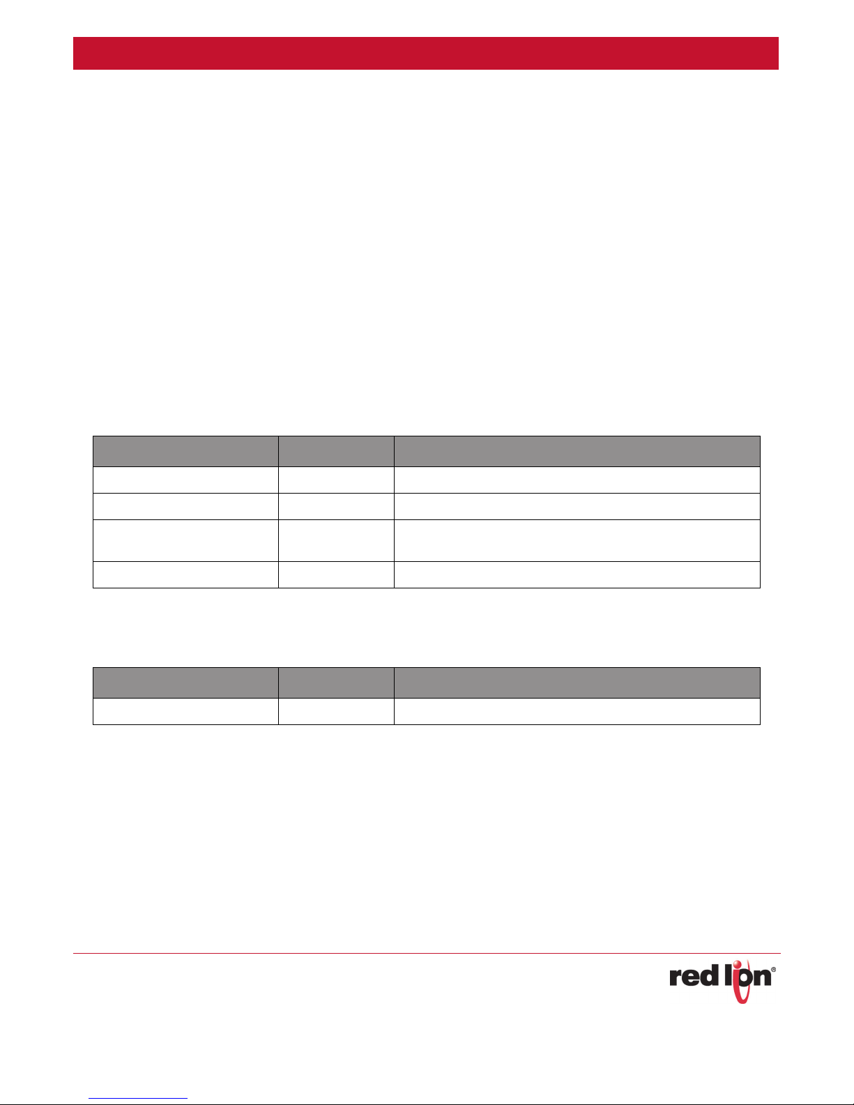
Publication History
The following information lists the release history of this document.
ISSUE/REVISION RELEASE DATE CONTENT DESCRIPTION
R04 March 2015 Updates to Warnings
R03 September 2014 Modifications to FCC Statement to cellular frequency bands.
R02 August 2014
R01 April 2014 First release.
Wi-Fi capability added. Change to operating temperature and
thermal performance.
Related Documents
The following information lists available documents related to this product.
ISSUE/REVISION RELEASE DATE DOCUMENT TITLE
version 6 June 2015 SN/RAM 6000 & RAM 9000 Software Manual
Document Ordering Information
To order additional documentation, the user can contact the local sales representative or Red Lion through the
ontact numbers and/or e-mail addresses listed on the back of the cover.
c
Document Comments
Red Lion appreciates all comments that will help us to improve our documentation quality. The user can submit
omments through the Red Lion Customer Service. Simply email us at customer.service@redlion.net.
c
RAM 9000 Series Hardware Guide 5
Page 6

Revised 2015-07-16
Additional Product Information
Additional product information can be obtained by contacting the local sales representative or Red Lion through the
contact numbers and/or e-mail addresses listed on the back of the cover.
Safety Information
Must consult guide in all cases where this symbol is marked.
Environmental:
Warning: The unit may become very hot to the touch in high temperature environments, so extreme caution
should be exercised in handling when energized. The unit should be disconnected from power and allowed to cool
for approximately 5 minutes before touching in high temperature applications.
Pollution degree: 2 (Per IEC 61010-1)
Electrical:
Must be powered by a “Class 2 source” only.
Properly ground the unit before connecting anything else to it. If the equipment is used in a manner “not” specified by Red Lion, the protection provided by the equipment may be impaired.
Overvoltage category: II (Per IEC 61010-1)
Warnings/Cautions/Notes
Warnings apply to situations where personal injury or death may result.
Cautions apply where damage to equipment may result
Notes apply where additional noteworthy information, not in the general text flow but applicable, is made available to the user.
Hazardous Location and Installation Requirements
These products should not be used to replace proper safety interlocking. No software-based device (or any other solid-state
device) should ever be designed to be responsible for the maintenance of consequential equipment or personnel safety. In
particular, Red Lion disclaims any responsibility for damages, either direct or consequential, that result from the use of this
equipment in any application.
All power, input and output (I/O) wiring must be in accordance with Class I, Division 2 wiring methods and in accordance with
the authority having jurisdiction.
Suitable for use in Class I, Division 2, Groups A, B, C and D hazardous locations, or non-hazardous locations only.
WARNING – EXPLOSION HAZARD: Substitution of components may impair suitability for Class 1, Division 2.
RAM 9000 Series Hardware Guide 6
Page 7

Revised 2015-07-16
WARNING – EXPLOSION HAZARD: When in hazardous locations, disconnect power before replacing or wiring modules.
WARNING – EXPLOSION HAZARD: Do not disconnect equipment unless power has been switched off or the area is known to
be non-hazardous.
WARNING – EXPLOSION HAZARD: Exposure to some chemicals may degrade the sealing properties of materials used in the
relays.
WARNING – EXPLOSION HAZARD: Batteries must only be changed in an area known to be non-hazardous.
These products are operator interface units to be used within control panels in hazardous locations. The enclosure shall be
suitable for the location.
A minimum IP54 rated enclosure is needed for ATEX unless an equivalent degree of protection is supplied by the location.
Hot-swapping is not for use in hazardous locations.
AVERTISSEMENTS POUR INSTALLATION ET ENDROITS DANGEREUX
Ces produits ne doivent pas être utilisés pour remplacer le verrouillage de sécurité approprié. Aucun dispositif basé sur un
logiciel (ou tout autre dispositif à l'état solide) devraient jamais être conçus pour être responsable de l'entretien de l'équipement consécutifs ou la sécurité du personnel. En particulier, Red Lion décline toute responsabilité pour les dommages, directs
ou indirects, résultant de l'utilisation de cet équipement dans n'importe quelle application.
Tout courant, câblage entrée et sortie (I / O) doit être conforme aux méthodes de câblage à la Classe I, Division 2 et conformément à l'autorité compétente.
Cet appareil est adapté pour utilisation en Classe I, Division 2, Groupes A, B, C, D endroits dangereux ou endroits non-dangereux.
AVERTISSEMENT – RISQUE D’EXPLOSION: La subsitution de tout composant peut nuire à la conformité de Classe I, Division 2.
AVERTISSEMENT – RISQUE D’EXPLOSION: Lorsque dans des endroits dangereux, débranchez le cordon d’alimentation avant
de remplacer ou de brancher les modules.
AVERTISSEMENT – RISQUE D’EXPLOSION: Ne débranchez pas l’équipement à moins que l’alimentation ait été coupée ou que
l’environnement est connu pour être non dangereux.
AVERTISSEMENT– RISQUE D’EXPLOSION: L’exposition à certain produits chimiques peut dégrader les propriétés d’étanchéité
des matériaux utilisés dans les relais.
AVERTISSEMENT – RISQUE D’EXPLOSION: Batteries doivent être changées dans une zone connue pour être non dangereuse.
Ces produits sont des unités d'interface opérateur qui doivent être utilisés à l'intérieur des panneaux de commande dans les
endroits dangereux. L'enclos doit être adapté à l’environnement.
Un boîtier IP54 minimum est nécessaire pour ATEX à moins qu’un degré équivalent de protection est fourni par l'emplacement. Pas de remplacements à chaud des modules dans les zones dangereuses.
RAM 9000 Series Hardware Guide 7
Page 8

Revised 2015-07-16
Statement of Limited Warranty
(a) Red Lion Controls Inc., Sixnet Inc., N-Tron Corporation, or Blue Tree Wireless Data, Inc. (the "Company") warrants that all Products shall be free from defects in material and workmanship under normal use for the period of
time provided in "Statement of Warranty Periods" (available at www.redlion.net) current at the time of shipment
of the Products (the “Warranty Period”). EXCEPT FOR THE ABOVE-STATED WARRANTY, COMPANY MAKES NO
WARRANTY WHATSOEVER WITH RESPECT TO THE PRODUCTS, INCLUDING ANY (A) WARRANTY OF MERCHANTABILITY; (B) WARRANTY OF FITNESS FOR A PARTICULAR PURPOSE; OR (C) WARRANTY AGAINST INFRINGEMENT OF
INTELLECTUAL PROPERTY RIGHTS OF A THIRD PARTY; WHETHER EXPRESS OR IMPLIED BY LAW, COURSE OF DEALING, COURSE OF PERFORMANCE, USAGE OF TRADE OR OTHERWISE. Customer shall be responsible for determining that a Product is suitable for Customer's use and that such use complies with any applicable local, state or
federal law.
(b) The Company shall not be liable for a breach of the warranty set forth in paragraph (a) if (i) the defect is a
result of Customer's failure to store, install, commission or maintain the Product according to specifications; (ii)
Customer alters or repairs such Product without the prior written consent of Company.
(c) Subject to paragraph (b), with respect to any such Product during the Warranty Period, Company shall, in its
sole discretion, either (i) repair or replace the Product; or (ii) credit or refund the price of Product provided that, if
Company so requests, Customer shall, at Company's expense, return such Product to Company.
(d) THE REMEDIES SET FORTH IN PARAGRAPH (c) SHALL BE THE CUSTOMER'S SOLE AND EXCLUSIVE REMEDY AND
COMPANY'S ENTIRE LIABILITY FOR ANY BREACH OF THE LIMITED WARRANTY SET FORTH IN PARAGRAPH (a).
RAM 9000 Series Hardware Guide 8
Page 9

Product Overview Revised 2015-07-16
RAM 9000 Cellular RTU Product Highlight
Chapter 1 Product Overview
Using a single web-based user interface, our cellular units simplify I/O, network and security configurations to
integrate complex hardware settings. This easy-to-manage configuration reduces the cost and complexity of
deploying and administering multiple devices at remote locations. Furthermore, an integrated configurable state
ful firewall provides intrusion protection and encrypted data access while a built-in Software Development Kit
(SDK) enables users to develop custom applications.
Working in conjunction with SixView Manager remote monitoring and control software, RAM RTUs provide lowcost, real-time access to outlying sites.
RAM 9000 Cellular RTU Product Highlight
• Supports Multi-Carrier 4G LTE connectivity with fall back to 3G and 2G
• Real-time access to mission-critical data through built-in Modbus gateway
• Software Development Kit (SDK) for custom application support
• Native support for DNP3 and Modbus protocols
• Integrated security firewall provides intrusion protection
• Simplified deployment and configuration with single web-based GUI
• Support for new and legacy devices with RS232/485 serial or RJ45 Ethernet
• Powerful event engine that can trigger built-in I/O or send SMS text messages based on real-time operational
data.
-
RAM 9000 Series Hardware Guide 5-14
Page 10

Product Overview Revised 2015-07-16
Specifications
Specifications
General Specifications
AT&T LTE with fallback to HSPA+
Bell Mobility LTE with fallback to HSPA+
Wireless Interfaces
Programmable Platform
Protocol Gateway
Generic LTE with fallback to HSPA+
Rogers LTE with fallback to HSPA+
TELUS LTE with fallback to HSPA+
Verizon LTE with fallback to EVDO
Configurable Events: up to 99 events can be triggered by I/O, Modbus registers, or over 200 system
variables which in turn can send text messages or control I/O
Software Development Kit (SDK)
C/C++/Perl
I/O Controller
Modbus RTU/TCP/ASCII
DNP3 - slave
32-bit ARM9 400 MHz CPU
System Performance
Tunneling IPsec, GRE, OpenVPN
IP
Routing Protocols OSPF, BGP, RIP
Clustering VRRP
GPS
Connectors
512 MB NAND Memory
128 MB RAM
NAT, port forwarding, dynamic DNS, DHCP
Stateful inspection firewall, IP Transparency
GNSS supported: GPS L1, GLONASS L1, Galileo E1
High RF sensitivity plus jamming detection/removal
Ethernet: One (1) or five (5) 10/100Base-T RJ-45 ports
WAN capability on port 2
Serial: One (1) RS-232 (DB9) 115200bps
One (1) RS-485 (screw block)115200bps
USB: One (1) USB 2.0 (mini)
Antennas: Three (3) SMA connectors (antenna, diversity, GPS)
One (1) RP-SMA connector (Wi-Fi optional)
RAM 9000 Series Hardware Guide 5-15
Page 11

Product Overview Revised 2015-07-16
Specifications
2 digital inputs
2 digital outputs
Inputs & Outputs
3 analog inputs
1 Form C Relay
See detailed I/O specifications in Section 1.2.5 below
Wi-Fi Interface
(Optional)
Power Input
Mechanical
Environmental
Complies with IEEE802.11b/g/n
Maximum output power up to 25dBm
Supports up to 150Mbps with 40MHz channel
Range: 8-30 VDC (12 or 24 VDC nominal)
Power consumption (less DO power):
• Standby: 4W (all models)
• Transmitting:
• 9911 & 9711: 5.0W - 9.4W (cellular only)
• 9931 & 9731: 5.0W - 13.6W (cellular and Wi-Fi)
Power consumption of DO (max each):
• 30W (1A @ 30 VDC)
Heat dissipation: 46 BTU/hour max; 20 BTU/hour typical
Dimensions: 132H x 127D x 70W mm (5.2” x 5.00” x 2.75”)
Material : Steel with black zinc coating
Weight: 906 g (2 lbs)
Operating temperature: -40°C to +75°C*
Shock: IEC60068-2-27
Vibration: IEC60068-2-6
Humidity: 5 to 95% non-condensing
Ingress Protection: IP30
Ethernet Interface
(10/100 Auto Sensing)
Serial interface
USB interface
1x or 2x RJ45 (Isolation 1500 Vrms 1 minute)
WAN capability on 2nd port
1x RS232 Serial DB9 115200bps
1x RS485 Serial Screws 115200bps (Isolation 1200 Vrms 1 minute)
1x USB 2.0 Device mini
1x USB 2.0 Host type A
LED indicators Dual Power, Status Reset, WAN, RSSI, RS232, RS485, GPS, SD, Ethernet Link & Activity
EMI/EMC – Emissions: FCC, Part 15 and Industry Canada, ICES-003; Class A; EN55022, IEC61000-6-4
Immunity: IEC61000-6-2 (EN61000-4-2,3,4,5,6,8)
Hazardous locations: Class I, Div. 2, Groups A, B, C, D, ANSI/ISA 12.12.01
Certification
Electrical safety: UL508/CSA22.2/14 (CUL): IEC61010-1
Carrier specific approvals (Contact Red Lion for latest)
RoHS compliant
RAM 9000 Series Hardware Guide 5-16
Page 12

Product Overview Revised 2015-07-16
Specifications
Warranty 3 years on design and manufacturing defects
Compliances The Red Lion Sixnet Series RAM 9000 products meet the following standards plus others:
Electrical Safety
These devices have been designed to meet the basic safety requirements of the following standards:
• CE per Low Voltage Directive and IEC 61010-1 (CE applies only to the -EU models. Please contact
Red Lion for availability)
• UL508 (Industrial control equipment), ANSI/ISA 12.12.01 (Hazardous Locations)
• CSA C22.2 No. 142 and No. 213 (per cUL)
EMC (emissions and immunity)
• CE per the EMC directive (CE applies only to the -EU models. Please contact Red Lion for availabil-
ity)
• IEC 61000-6-2: Immunity in industrial environments
• IEC 61000-6-4: Emmissions in industrial environments
• FCC part 15 and ICES 003. See FCC statement on page 6.
• EN 55022 (CISPR22)
This equipment has been tested and found to comply with the limits for a Class A digital device, pursuant to part 15 of the FCC rules. These limits are designed to provide reasonable protection against
harmful interference when the equipment is operated in a commercial environment. This equipment
generates, uses, and can radiate radio frequency energy; and if not installed and used in accordance
with the instructions, may cause harmful interference to radio communications. Operation of this
equipment in a residential area is likely to cause harmful interference to radio communications, in
which case the user will be required to correct the interference at their own expense. Warning:
Changes or modifications to this unit not expressly approved by the party responsible for compliance
could void the user's authority to operate the equipment.
Information to the user: If this equipment causes interference to radio or television reception, which
can be determined by turning the equipment off and on, the user is encouraged to try to correct the
interference by one or more of the following measures: In order to meet FCC emissions limits, this
equipment must be used only with cables that comply with IEEE 802.3. If necessary, the user should
consult the dealer or an experienced radio/television technician for additional suggestions. The user
may find the following booklet prepared by the Federal Communications Commission helpful: “How
to Identify and Resolve Radio-TV Interference Problems”. This booklet is available from: U.S. Govern
ment Printing Office, Washington, DC 20402, Stock No. 004-000-00345-4
WEEE compliance
These devices comply with the WEEE directive. Do not throw away these devices in the standard
trash. Contact Red Lion regarding proper disposal.
-
RoHS compliance
These devices comply with the RoHS directive and are considered lead and other hazardous substance free.
*-40°C to +75°C - See Thermal Performance and Considerations section in Chapter 2.
Note: All specifications are subject to change. Consult the Red Lion website for more information
RAM 9000 Series Hardware Guide 5-17
Page 13

Product Overview Revised 2015-07-16
Specifications
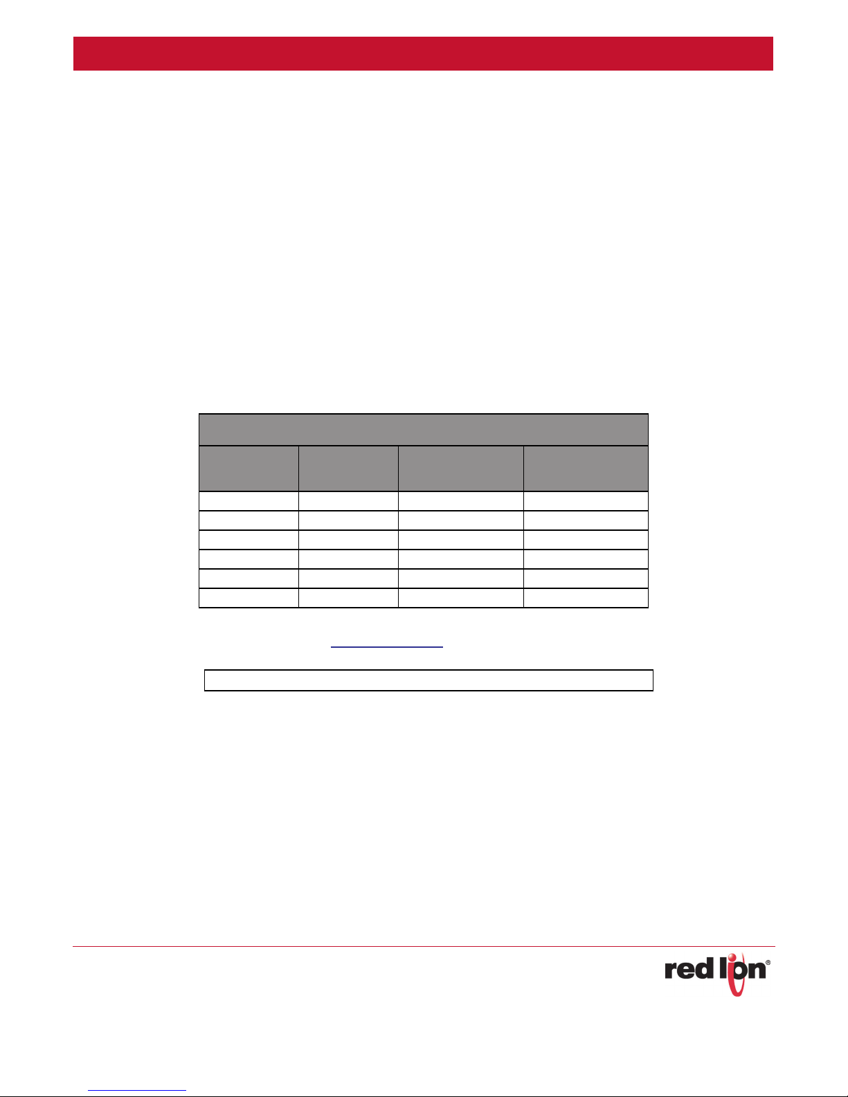
RAM 9000 Model Comparison Chart
FEATURE RAM-9X01 RAM-9X11 RAM-9X31
Cellular x = 6 for 3G
Wi-Fi - - 1
GPS 1 1 1
Ethernet Port 1 2 2
RS232 Port 1 1 1
RS485 Port 1 1 1
USB Host Port 1 1 1
USB Device Port 1 1 1
SIM Card Slot 2* 2* 2*
SD Card Slot 1 1 1
Discrete Input 2 2 2
Discrete Output 2 2 2
Relay Output 1 1 1
Analog Input 3 3 3
* A future firmware update is required to utilize the second SIM slot.
Contact Red Lion for availability of this feature.
RAM 9000 Cellular RTU View
x = 7 for 4G LTE
x = 9 for 4G LTE+
x = 6 for 3G
x = 7 for 4G LTE
x = 9 for 4G LTE+
x = 6 for 3G
x = 7 for 4G LTE
x = 9 for 4G LTE+
RAM-9x01
RAM 9000 Series Hardware Guide 5-18
RAM-9x11
RAM-9x31
Page 14
Product Overview Revised 2015-07-16
Specifications
Power Specifications and Consumption
Power Input:
• Range: 8-30 VDC (12 or 24 VDC nominal)
• Power consumption (less DO power):
• Idle: 4W
• Typical: 5 - 6 W
• Maximum: 6 - 14 W (depends on model)
• Power consumption of DO (max. each):
• 30W (1A @ 30 VDC)
• Heat dissipation: 46 BTU/hour max.; 20 BTU/hour typical
Power input to the unit is protected against reverse polarity and over-voltage up to 33VDC. The router’s power
consumption is as follows:
TYPICAL POWER CONSUMPTION (WATTS)
MODEL STANDBY
RAM-99x1 4.0 5.0 9.4
RAM-97x1 4.0 5.0 9.4
RAM-96x1 4.0 4.6 5.5
RAM-9931 4.0 5.0 13.6
RAM-9731 4.0 5.0 13.6
RAM-9631 4.0 4.6 9.7
Note: Wiring instructions are provided in
To meet UL requirements, a “Class 2 Source” power supply is required.
Electrical Specifications and Pinout
Discrete Inputs:
• 2 Channels
• Isolated fully differential
• Isolation (channel to channel) = 1 KV
• Voltage range = 8-30 VDC
• Guaranteed ON voltage = 2.8 VDC
• Guaranteed OFF voltage = 2.7 VDC
• Input resistance = 315K Ohms
TRANSMITTING
MINIMUM
TRANSMITTING
MAXIMUM
I/O Wiring section in Chapter 2 of the Hardware Installation chapter.
RAM 9000 Series Hardware Guide 5-19
Page 15

Product Overview Revised 2015-07-16
Specifications
• Input current @ 24 VDC = 10 mA
• Filtered ON/OFF delay = 25 ms (10 Hz max count rate)
• Count resolution = 16 or 32 bits
Discrete Outputs:
• 2 Channels
• Sourcing of module power 8-30 VDC
• Max. output load per channel = 1 A (up to 35°C)
• Derate to 0.7 A up to 50°C
• Derate to 0.55 A up to 70°C
• Derate to 0.4 A up to 80°C
• Derate to 0.3 A p to 85°C
• Min. output load per channel = 1 mA
• Max. OFF state leakage current = <0.05 mA
• Inrush current (100 mA surge) = 5A
• Typical ON voltage drop (@1 A) = 0.13 VDC
• Short circuit protection = self-reset fuses (trip above 1.5 Amp at 20C)
Relay Outputs Specs:
• 1 channel
• Relay type = Form C (NO/NC)
• Minimum output voltage = 0 VAC/VDC
• Maximum output voltage = 110 VDC, 125 VAC
• Minimum switching capacity = 10μA, 10 mV DC
• Maximum load current per output (30 VDC) = 2 Amps
• Maximum load current per output (125 VAC) = 0.3 Amps
• Minimum OFF resistance = 1000 Meg Ohms
• Maximum relay turn ON time = 4 ms
• Maximum relay turn OFF time = 4 ms
• Load current versus contact voltage chart:
RAM 9000 Series Hardware Guide 5-20
Page 16

Product Overview Revised 2015-07-16
Specifications
Analog Input Specs:
• 3 channels
• Ranges = 4-20 mA or 0-10 VDC
• Ranges are software selectable
• A/D resolution = 16 bits (0.003%)
• Input resolution = 2 uA or 0.5 mV
• Full scale accuracy (@20°C) (after field calibration) = +/- 0.1%
• Input span adjustability = +/- 25%
• Input offset adjustability = +/- 25%
• Span temperature coefficient +/- 50 ppm per °C
• Offset temperature coefficient +/- 50 ppm per °C
• Input impedance
• Current ranges = 100 Ohms
• Voltage ranges = 10KOhms
• Current protection (current range) = self-resetting fuses
• DMRR at 50/60 Hz = 66dB
• Fastest update time = 120 ms per channel
• Self-calibration interval = 5 seconds
RAM 9000 Series Hardware Guide 5-21
Page 17
Product Overview Revised 2015-07-16
Specifications
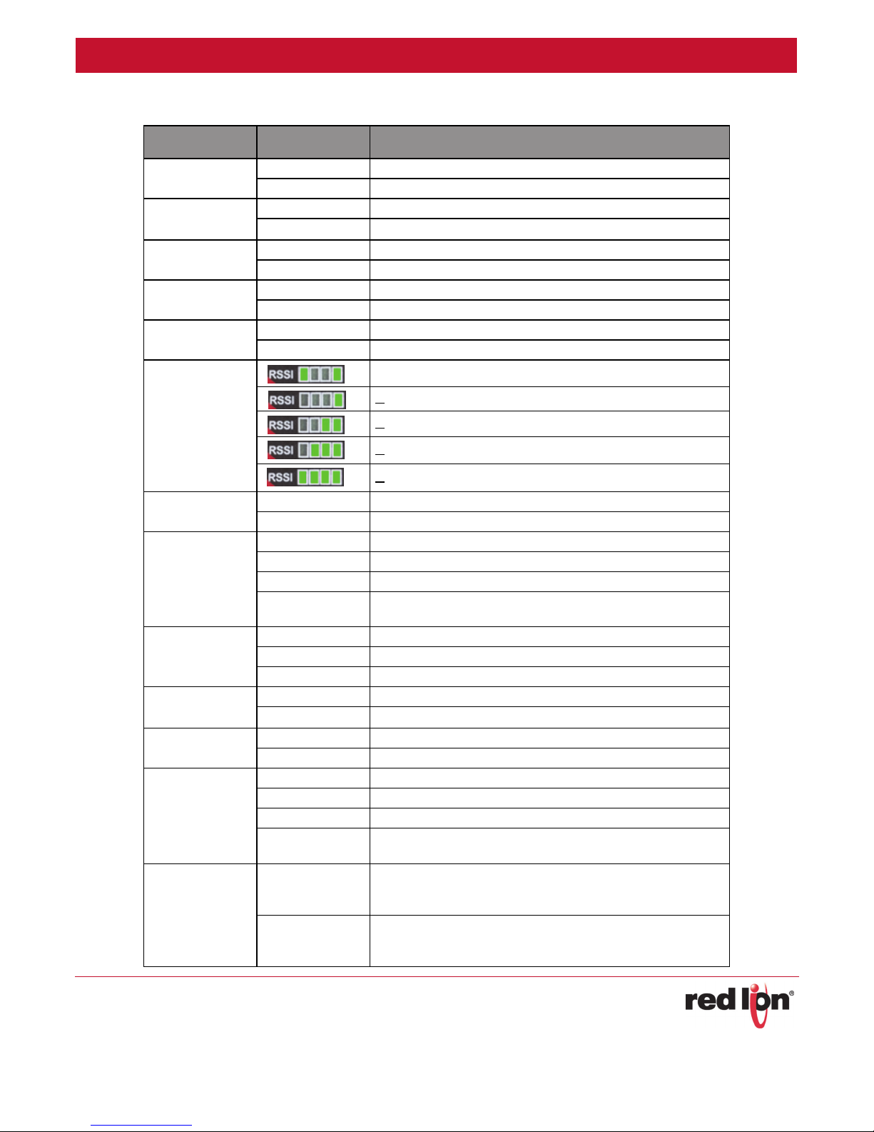
Indicator Lights
LED STATUS CORRESPONDING STATE
P1
P2
(Backup Power)
SD
GPS
WAN
RSSI
Reset
Status
Ethernet Link and
Activity
(Yellow)
Ethernet Speed
(Green)
RS485
RS232
RLY1
ON Power is being applied to the primary input
OFF Power is not being applied to the primary input
ON Power is being applied to the secondary input
OFF Power is not being applied to the secondary input
ON SD Card mounted
OFF No SD Card mounted
ON Position fix available
OFF No position fix available
ON Cellular connection is established
OFF Cellular connection is not established
Low Signal / No service
> - 109 dBm (Low but valid signal)
> - 99 dBm (Lower but valid signal)
> - 89 dBm (Avg signal)
> - 80 dBm (Excellent signal)
ON
OFF
ON
OFF
FLASH
STROBE (Fast
Flash)
ON
OFF
FLASH
ON
OFF
ON
OFF
ON
OFF
SLOW FLASH
STROBE (Fast
Flash)
ON
OFF
Unit is booting. Not ready.
Unit is functioning normally
Unit is booting up.
Normal operation
Unit entering reflashing mode. Do not disturb.
System error. Contact Red Lion Technical Support.
Link detected
No link detected
Linked and active communications detected
100 Mbps link speed detected
10Mbps link speed detected
Serial connection is configured for use
Serial connection is not configured for use
Serial connection is established – with no data activity with host
Serial connection is not established
Serial connection is established – with data activity with host
Unit is reflashing. Do not disconnect power!
The relay output is being activated. The Normally Open terminal
will be ON (closed). The Normally Closed terminal will be OFF
(open)
The relay output is not being activated. The Normally Open terminal
will be OFF (open). The Normally Closed terminal will be ON
(closed).
RAM 9000 Series Hardware Guide 5-22
Page 18

Product Overview Revised 2015-07-16
Specifications
LED STATUS CORRESPONDING STATE
DO1/DO2
DI1/DI2
A
B
ON
OFF
ON
OFF
Future
Future
The corresponding discrete output is ON and sourcing power.
The corresponding discrete output is OFF and not sourcing power.
A valid voltage is detected on the corresponding discrete input.
A valid voltage is not being detected on the corresponding discrete
input.
Reserved for future use.
Reserved for future use.
Bootup LED Sequence
Stage 1: Power On
When the unit is first powered on, the P1/P2 LEDs will indicate that power has been detected.
Stage 2: CPU Initialized
The LED stacks on each side of the unit will scroll rapidly. When initialization is complete, all front LEDs will be on.
Stage 3: Kernel Loading
The Reset LED will turn off, but Status, A, B and RS232 will remain on.
Stage 4: Filesystem Mounted
The Status and RS232 LEDs will turn off and go into normal mode. A and B will remain on.
Stage 5: System services starting
The A and B lights will now turn off. All front panel LEDs should be in normal mode operation. Your unit should be
fully functional within a few seconds.
Data Interface Specifications: Serial, Ethernet & USB
Ethernet Port
The unit’s 10/100Mbps port is compliant with the EIA-568 standard. The modem’s ports are auto-sensing so they
can be used with either a straight or crossover RJ45 cable to connect to host ports.
The RAM-9701 model has one Ethernet port and the RAM-9711, RAM-9731, RAM-9911, and RAM-9931 models
have two Ethernet ports.
Ethernet Plug &
Connector Pin Positions
RAM 9000 Series Hardware Guide 5-23
Page 19

Product Overview Revised 2015-07-16
Specifications
USB Device Port
This is a USB 2.0 Device interface on a Mini B connector. It offers Ethernet-over-USB RNDIS driver
connection with all major operating systems. Driver installation and detection should be automatic on a properly configured Operating System.
USB Host Port
This is a USB 2.0 Host interface on a standard type A connector.
Specifications:
• USB Host USB 2.0 (1.5 / 12 / 480 MBit/s)
• Complies with Univ
dware over current protected (1.0 A max per port)
• Har
• Incr
• Not electric
eased Retention Connector (Complies with Class 1,. DIV II minimum withdrawal requirement of 15N)
ally isolated
• Only use shielded USB s
ximum cable length: 5 m
• Ma
ersal Serial Bus Specification Rev 2.0
tandard cable
Note: No software functions have been defined for this port yet. This functionality will be available in a future firmware
release.
Serial Port
The unit’s serial port is an RS232 DTE, compliant with EIA-232 standard. The connector used is DB9 male and is
shown in the illustration below.
Serial Connector (looking at front of unit)
RAM 9000 Series Hardware Guide 5-24
Page 20

Product Overview Revised 2015-07-16
Specifications
RS485 Port
The unit’s RS485 serial port is for 2 wire, half-duplex connections up to 115,200 baud rate. This
port is fully isolated up to 1200 Vrms (1 minute). A pluggable screw terminal is provided to make
the RS485 connections. Refer to the RS485 wiring section for more details.
Mode/Reset Button functions
The Mode and Reset buttons are found on the front of the unit. Each is a momentary tactile button. It is recommended to use a straightened paper clip to press these buttons. Refer to the table below for the function of each
ton.
but
Reset Button:
FUNCTION PATTERN DESCRIPTION
Hard Reset Press and hold for more than 7 seconds Unit will perform a hard reset without a clean shutdown.
Mode But
ton:
This button has 2 full feature sets depending on WHEN it is pressed: Boot time or Run time.
Boot Time: These features are only active at boot time. To use these features, power cycle your unit (or hold
Reset) and immediately push and hold the Mode button for the desired function sequence listed below:
FUNCTION PATTERN DESCRIPTION
Reset to Factory Defaults Hold until RS485 LED flashes Restores unit config to the original state.
Advanced Firmware
Upgrade
RF module USB bypass
mode: SIM1
RF module USB bypass
mode: SIM2
Hold until WAN LED flashes
Hold until GPS LED flashes
Hold until SD LED flashes
Sets the unit to automatically download firmware files
using the advanced upgrade procedure.
Puts modem into RF module USB bypass mode with SIM1
selected.
Puts modem into RF module USB bypass mode with SIM2
selected.
Run Time: These features are active during run time, once the unit is fully booted and idle.
Usage of the Mode push button, during normal runtime:
1. Hold in the Mode button for about 3 seconds until the 4 RSSI signal lights flash. The lights will then go dark. This is
entering action selection mode.
2. Push the button 1 time to increment the action counter. Each time the button is pressed, the RSSI lights will increment
once. The lights count in a binary pattern.
3. Once an action number is selected, the pattern on the light bar will flash. This indicates your action is executing.
RAM 9000 Series Hardware Guide 5-25
Page 21

Product Overview Revised 2015-07-16
Specifications
COUNT PATTERN ACTION DESCRIPTION
0 None No action will be performed
A GatherStats will be run and saved to ROM for further review. If a
1 GatherStats
2 TriggerSVM
3 Reset Cellular The cellular module will be reset.
4 Reboot Unit Unit will be rebooted cleanly.
5 Ethernet restore
6 Backup Configs
7
Force Cell
Provisioning
network connection is available, a copy will be sent to technical
support. RSSI will scroll down while Gatherstats is running.
A Check-In will be triggered to all configured SixView Manager
servers.
Eth0 and Eth1 will be temporarily restored to system default IP
address. This will allow access to a known IP. This change is not
saved and will be reverted after a reboot.
A copy of the system configuration will be backed up to system
storage.
Force a cellular activation attempt. Sprint and Verizon 3G only.
8 Force PRL Update Force a cellular PRL Update. Sprint and Verizon 3G only.
9 TBD
10 TBD
11 TBD
12 User1 User Defined
13 User2 User Defined
14 User3 User Defined
15 User4 User Defined
RAM 9000 Series Hardware Guide 5-26
Page 22

Product Overview Revised 2015-07-16
Ordering Guide
Ordering Guide
MODEL
NUMBER
RAM-9911-xx RAM 1 1 2 (WAN/LAN) N 4G LTE DC powered
RAM-9931-xx RAM 1 1 2 (WAN/LAN) Y 4G LTE DC powered
* See Band/Frequency table for compatibility
** Carrier is pre-configured on device. Carrier can be selected via software.
Where xx = carrier code
SERIES
SERIAL ETHERNET
RS-232 RS-485 10/100
WI-FI CELLULAR
POWER
CONNECTOR
DEFAULT
CARRIERS**
(AT) AT&T
(VZ) Verizon
(AM) Generic*
RAM 9000 Series Hardware Guide 5-27
Page 23

Hardware Installation Revised 2015-07-16
Mounting the RAM 9000 Cellular RTU
Chapter 2 Hardware Installation
Mounting the RAM 9000 Cellular RTU
There are three different ways to mount a RAM 9000 series unit:
• Horizontally using two (2) screws (#6 up to #10) onto its horizontal mounting feet.
• Vertically using two (2) screws (#6 up to #10) onto its vertical mounting feet.
• Vertically on a DIN rail using the supplied DIN rail clip.
Note: Allow enough room to route the Ethernet, serial, I/O and other cables.
DIN Rail Mounting & Removal
The RAM 9000 has a DIN rail clip pre-mounted to the back of the unit. To panel mount the unit,
the clip must be removed by removing the three (3) screws holding it in place. See the image at
right for reference.
The DIN clip has an integral spring mechanism that keeps it securely attached to the rail. Refer
to the diagrams below for how to mount and remove the unit to a standard EN50022 DIN rail.
Note: For best performance it is recommended that a DIN rail spacer (such as an end clamp) be
used between the RAM 9000 and adjacent devices. This will leave an air gap for best heat dissipation off of the
case.
RAM 9000 Series Hardware Guide 2-28
Page 24

Hardware Installation Revised 2015-07-16
DIN Rail Mounting & Removal
Mounting Instructions:
Removal Instructions:
RAM 9000 Series Hardware Guide 2-29
Page 25

Hardware Installation Revised 2015-07-16
Mechanical Dimension Diagram s
Mechanical Dimension Diagrams
Antennas and Wireless
Warning: This device is not intended for use within close proximity of the human body.
Antenna installation should allow for a separation of at least 20cm from all personnel.
The Red Lion RAM 9000 series may have up to four (4) antenna connectors available, labeled Antenna, Diversity,
GPS and Wi-Fi.
• An
tenna: This is the main antenna that is used for data transmission. It is mandatory to have the Antenna port
connected to an antenna.
ersity/MIMO: This port is used for RX diversity on 3G connections and MIMO for LTE connections. Receive
• Div
Diversity or MIMO is a transmission technique that consists of using two separate antennas to achieve the
most robust cellular signal possible. Diversity will help achieve fast, reliable data throughput in applications
that require a high amount of bandwidth. This antenna is not mandatory for 3G, however it is recommended
and will improve throughput in low signal and fringe areas. This antenna is
MIMO operation.
required for compliance with LTE
RAM 9000 Series Hardware Guide 2-30
Page 26

Hardware Installation Revised 2015-07-16
Antennas and Wireless
To get the best performance, this second antenna should be placed at a minimum of 5/8 of a wave length away
from the other antenna. Therefore, the minimum spacing for antennas in the 800 MHz frequency is 5/8 * 13.5”
= 8.5”. The diversity antenna can be spaced further away than this, ideally in increments of 13.5”, 22”, 35”, etc.
For a 1900 MHz only network, the optimal distance would be 5/8 * 6.2” = 4”. Orienting the antennas differently
from one another may also improve performance, particularly when the antennas are close together.
• GPS: This unit uses an active antenna only. It is used for receiving signals only. Please refer to the Red Lion
website for information on GPS antennas.
• Wi-Fi: A reverse-SMA (female) connector is provided on the RAM-9x3x units that include Wi-Fi connectivity.
Please use a 50 ohm cable and antenna that are rated for Wi-Fi connectivity per IEEE 802.11b/g/n. Please refer
to the Red Lion
website for information on Wi-Fi antennas.
Per FCC requirements the antenna gain including cable loss must not exceed 7.5 dBi in the Cellular band, 3 dBi in
the PCS band, 5.5 dBi for LTE Band 4, and 9 dBi in the LTE Band 17 for RF exposure purposes of 2.1091. The
antenna(s) used for this transmitter must be installed to provide a separation distance of at least 20 cm from all
persons. The antenna(s) used for this transmitter must not be co-located or operating in conjunction with any
other antenna or transmitter except in accordance with FCC multi-transmitter evaluation procedures.
Cellular Antenna and Cable Specifications
The selected cellular antenna(s) must meet the following specifications:
• Nominal 50 ohm impedance
• Voltage Standing Wave Ratio (VSWR) less than 2.5:1
• Male SMA connector
Frequency Specifications
RAM-96xx
TECHNOLOGY BANDS FREQUENCIES ANTENNA CONFIGURATION
CDMA/EVDO
RAM-97xx
TECHNOLOGY BANDS FREQUENCIES ANTENNA CONFIGURATION
LTE 1, 4, 17
Fallback HSPA+ 1, 2, 5, 6 800/850/1900/2100 Diversity Support
Fallback GSM/GPRS/EDGE - 850/900/1800/1900 MHz -
BC0, BC1 800/1900 MHz Diversity Support
700/1900 & 1700 (AWS)/
2100(AWS) MHz
MIMO Required
RAM 9000 Series Hardware Guide 2-31
Page 27

Hardware Installation Revised 2015-07-16
Antennas and Wireless
RAM-99xx
TECHNOLOGY BANDS FREQUENCIES ANTENNA CONFIGURATION
LTE 2, 4, 5, 13, 17, 25
Fallback CDMA/EVDO BC0, BC1, BC10 800/1900 MHz Diversity Support
Fallback HSPA+ 1, 2, 4, 5, 8
Fallback GSM/GPRS/EDGE - 850/900/1800/1900 MHz -
700/850/1900 & 1700 (AWS)/
2100(AWS) MHz
850/900/1900/2100 & 1700(AWS)/
2100(AWS) MHz
MIMO Required
Diversity Support
The length of the antenna cable may affect the signal strength. Choose the appropriate cable type and length. The
table below can help pre-determine the loss to expect.
CABLE TYPE LOSS PER 100 FEET
8216 (RG58) 31 dB
8267 (RG213) 7.6 dB
LMR-400 3.9 dB
LMR-500 3.15 dB
LMR-600 2.5 dB
LMR-1200 1.26 dB
dB loss per 100 feet of cable type
GPS Antenna
The GPS chipset used in this device supports a 50 ohm active GPS antenna and is capable of GPS and Glonass signal reception. Ascertain that the GPS antenna cabling uses an SMA-M type connector. For optimal results, the GPS
antenna should be located so that is has clear and unobstructed access to the sky.
Installation and Verification
When installing the antenna, follow the FCC and Industry Canada guidelines and keep the following in mind:
• Mount the antenna(s) at least 30 cm (12 inches) from other antennas
• Do not install the antenna in a closed metallic enclosure (such as a cabinet or the trunk of a car).
Once a RTU has a signal, the Signal LED indicator will start flashing according to the signal strength. Additionally,
the Web Interface can display the received signal strength (RSSI) on the status page. The unit should have at the
very least one bar of signal strength.
RAM 9000 Series Hardware Guide 2-32
Page 28

Hardware Installation Revised 2015-07-16
Ethernet cable
Wi-Fi Antenna
The Wi-Fi cabling and antenna must meet the following requirements:
• 50 ohm impedance
• RP-SMA (Male) connector
• Antenna designed for Wireless LAN or Wi-Fi
• Recommended antenna frequency rating: 2.4 GHz
• Recommended antenna bandwidth rating: 1.0 GHz
The Wi-Fi performance specifications of the RAM-9000 are shown in the table below:
RADIO
Antenna 1 U.FL-R-SMT compliant connector (1T1R)
Output Power @ 25°C
(±2dB)
Sensitivity
Operating Frequency
Modulation
IEEE 802.11b
11 Mbps: 23 dBm
IEEE 802.11b
11 Mbps: -90 dBm
IEEE 802.11b/g/n 20 MHz ISM Band
• USA (FCC): 2.412 GHz ~ 2.462 GHz (CH1 ~ CH11)
• CD/CHINA: 2.412 ~ 2.472 GHz (CH1 ~ CH13)
IEEE 802.11g/n 40 MHz Band
• USA (FCC): 2.422 GHz ~ 2.452 GHz (CH3 ~ CH9)
• CE/CHINA: 2.422 ~ 2.462 GHz (CH2 ~ CH11)
IEEE 802.11b (DSSS): CCK, DQPSK, DBPSK
IEEE 802.11g/n (OFDM/DSSS): QAM-64, QAM-16, QPSK, BPSK
IEEE 802.11g
6 Mbps: 23 dBm
54 Mbps: 21 dBm
IEEE 802.11g
6 Mbps: -92 dBm
54 Mbps: -75 dBm
IEEE 802.11n
MCS0: 23 dBm @ HT20 / HT40
MCS7: 21 dBm @ HT20 / HT40
IEEE 802.11n
2.4 GHz MCS0: -90 dBm (HT20)
MCS7: -72 dBm (HT20) MCS0: -88
dBm (HT40) MCS7: -68 dBm (HT40)
Ethernet cable
If you are connecting to the unit via the Ethernet port, you will need a straight or crossover minimum category 5
cable with two 8-pin RJ45 connectors on each end.
To visually confirm that Ethernet cabling was done properly, check the LED indication on the Ethernet port of the
unit. The link LED should be on when the correct cable is used.
Note: A shielded cable is required to fully meet EMC standards.
RAM 9000 Series Hardware Guide 2-33
Page 29

Hardware Installation Revised 2015-07-16
USB Device Cable
USB Device Cable
This is an Ethernet-over-USB connection which behaves like an Ethernet connection. It can be connected to a PC
with all major operating systems. Driver installation and detection should be automatic on a properly configured
OS. If you are connecting to the unit via the USB port, you will need a Type A plug to Mini-B plug USB cable. In
order for the USB connection to work, you need to install the Sixnet USB driver which is available at
www.redlion.net.
USB Host Cable
This port will accept directly mounted devices such as a USB memory stick, wireless adapters, etc. Remote devices
can be connected to by using a USB cable. The end of the cable that connects to the unit must be a standard USB
Type A plug.
Note: No software functions have been defined for this port yet. This functionality will be available in a future
firmware release. Contact Red Lion for expected availability.
Serial RS485 Wiring
RS485 connections are made to screw terminals on the top of the RTU. These terminals provide a RS485 (2-wire,
half duplex only) connection to a network of RS485 devices connected in a bus topology, or a one-one-one connection to another RS485 device. Never connect RS485 devices in a star topology. Five terminals (for signal
ground, voltage bias, termination, 485- and 485+) are provided. Generally, connect + to + and - to - between units,
however since there is no standard for RS485 terminal designations you may need to connect + to - and - to + in
some cases. No damage to the RTU will result if incorrectly connected. It is highly recommended that the signal
ground (IGND) is tied to an appropriate ground (if available) between all RS485 units. The signal ground is fully isolated from the P1 and P2 ground and power. Make sure to use a good quality communication cable with three
conductors (twisted is preferred) plus a shield. To prevent ground loops, the shield should be connected to chassis
ground on only one end of any cable run.
Note: If you have existing wiring that has only two conductors and a shield, the shield to connect the signal
grounds between stations can be used. This is not optimal (especially for long cable runs) but should work in most
situations.
RS485 Termination: The RTU has RS485 termination components (120 ohm resistor and a capacitor connected in
series) already inside. To terminate your RS485 network, tie the “TERM” terminal to the RS485 - terminal. Make
sure to use the same type and size conductor as already used for the RS485 - connection. It is recommended that
both end stations of the RS485 network be terminated. Termination is only needed at the stations on the endpoints of the bus, never terminate any of the other stations between the endpoints. For other devices, please
refer to their user manual for termination instructions.
Bias Resistors: On a RS485 2-wire network, a pair of bias resistors (1K ohm typically) acting upon the transmit/
receive wires may be required. If bias resistors are not present, the receive inputs on some RS485 devices may
react to noise on the floating wires. The bias resistors will force the transmit/receive wires to a known (non-floating) state when none of the RS485 devices are transmitting data. Some RS485 devices have bias resistors built-in
and are enabled through DIP-switch or jumper settings. Make sure there is only one pair of bias resistors acting
upon the network. The RAM 9000 provides a way to easily connect external biasing resistors if needed. To bias the
RAM 9000 Series Hardware Guide 2-34
Page 30

Hardware Installation Revised 2015-07-16
Serial RS485 Wiring
RS485+ connect a resistor of the desired value between the VBIAS terminal and the RS485+ terminal. To bias the
RS485- connect a resistor of the desired value between the IGND terminal and the RS485- terminal. As mentioned
above, 1K ohms is a typical value for a biasing resistor but other RS485 devices may recommend other values.
Note: The RAM 9000 RS485 port is designed in such a way as to never need biasing, but it includes the VBIAS
screw as a convenience for use with 3rd party devices that require network biasing but lack the VBIAS connection.
If the RS485 network is made up exclusively of RAM 9000 devices, then these bias resistors are not necessary.
PIN NAME DESCRIPTION
IGND Isolated Ground RS485 signal ground optically isolated from other ground.
VBIAS Voltage Bias Connect to add RS485 Network Biasing.
TERM Termination Connect to add RS485 Network Termination.
485- RS485- Two wire RS485 negative terminal.
RS485 (Top of unit)
485+ RS485+ Two wire RS485 positive terminal.
Note:
• Terminals are sized to hold 28 to 12 gauge wire, 12 AWG wire area is 3.31mm2.
• Torque spec for terminals is 0.5 Nm.
• Use copper wire rated to 90°C or above.
RAM 9000 Series Hardware Guide 2-35
Page 31

Hardware Installation Revised 2015-07-16
Serial RS232 Cable
RS485 Wiring Diagram
Serial RS232 Cable
The unit has a serial DTE RS232 port. In this port all of its serial port pins are enabled. If all the pins are enabled on
the attached serial device, it is important to know whether the device is using DTE or DCE as a communication
mode.
If using custom wiring or if some pins are disabled, follow the guidelines below. The wiring will vary depending on
whether the attached serial device is a DTE or DCE.
Note: A shielded cable is required to fully meet EMC standards.
RAM 9000 Series Hardware Guide 2-36
Page 32

Hardware Installation Revised 2015-07-16
Power Source
Power Source
Important
Any installation involving electrical wiring and connections should be done by someone who is experienced in this
field. The safety of any system incorporating the equipment, is the responsibility of the assembler of the system.
Follow all local and national wiring codes.
Powering the unit
The unit will boot up as soon as an 8 to 30 VDC is applied to one of its power inputs and immediately shuts off
when this input voltage is removed or drops below or around 7.4 VDC.
Testing the power connection
Check the P1 and P2 LED’s on the RTU: if either or both are green, then the unit is powered. If both are OFF, then
review the installation procedures or contact Red Lion Technical Support for further assistance.
Must consult guide in all cases where this symbol is marked.
6-pin Screw Terminal
Power is supplied to the unit via the 6-pin screw terminal on the top panel. Use copper wiring with a minimum
insulation rating of 90°C. The pins are described as follows:
PIN NAME DESCRIPTION
P1+ Power 1+ This is the primary power source input.
P1- Power 1- This is the primary power source input.
Chassis Ground Tie to the panel or chassis ground.
P2+ Power 2+ This is the secondary power source input.
P2- Power 2- This is the secondary power source input.
Power Connector
(top of unit)
Note: for best grounding, ground both chassis ground screws in the connector AND the ground screw next to the
power connector.
To meet UL requirements, a “Class 2 Source” power supply is required.
Chassis Ground Tie to the panel or chassis ground.
Note:
• Terminals are sized to hold 28 to 12 gauge wire, 12 AWG wire area is 3.31mm2.
• Torque spec for terminals is 0.5 Nm.
• Use copper wire rated to 90°C or above.
RAM 9000 Series Hardware Guide 2-37
Page 33

Hardware Installation Revised 2015-07-16
Battery
Power Input Diagram
Battery
The battery is used to power the SRAM memory and the real-time clock when the unit does not have main power
(at P1 or P2). When needed, replace the battery with a Rayovac BR1225X-BA or a Panasonic BR1225A/BN battery.
The battery is located at the rear of at the rear of the unit and is expected to last up to 9 months of the unit being
continuously powered down. The battery is not being drained when the unit has power applied to either P1 or P2
or both. Under typical operating conditions the battery is estimated to last 5 years or more. However, it is recommended to replace the battery every 3 years to ensure no loss of functionality.
Rayovac BR1225X-BA*
RAM 9000 Series Hardware Guide 2-38
Panasonic BR1225A/BN
*Must use this one for ATEX
and/or IECeX applications.
Page 34

Hardware Installation Revised 2015-07-16
Battery
Note: The unit may ship with a battery pull-tab insulator in place that prevents the battery from discharging prior
to first use. Remove the insulator when you are ready to install and use the unit. The insulator is removed by simply pulling it out.
Note: The battery does not provide power to the unit either as a main power source or as a backup. It only powers
the SRAM memory and real-time clock, and only when there is no power supplied to either P1 or P2.
Note: For full temperature ATEX and/or IECeX compliance you must use a battery rated to 125C such as the Panasonic BR1225A/BN.
Battery Removal and Installation:
Step 1: Open Battery door on bottom of unit by removing the single screw.
Step 2: Insert a small flat-head screwdriver into the slot as shown below:
Step 3: Leverage back on the handle of the screwdriver to pop out the battery assembly:
RAM 9000 Series Hardware Guide 2-39
Page 35

Hardware Installation Revised 2015-07-16
SIM Cards
Step 4: Remove old battery from the holder and replace with a new battery of the proper type (see above).
Step 5: Insert battery holder with a new battery into the battery slot and push into slot until you hear and feel
it snap into place:
Step 6: Replace the battery door.
SIM Cards
The RAM 9000 has 1 or 2 SIM card sockets, depending on the model. The SIM sockets are found under a panel on
the bottom of the unit. Remove the one screw to access the SIM socket(s).
Note: The second socket (SIM2) is currently not supported. A future firmware release will
be needed to support SIM2.
RAM 9000 Series Hardware Guide 2-40
Page 36

Hardware Installation Revised 2015-07-16
SD Card
SD Card
The RAM 9000 has an SD memory card socket. This socket is found under a small door in the front face of the unit.
Remove the one screw to access the SD card socket. To install an SD card, insert in the orientation show on the
label until you hear a click. The SD card when properly inserted should sit just behind the door as shown below. To
remove the SD card push on the card until you hear a click, then remove pressure and the card will release.
Note: A future firmware update is required to utilize the SD Card feature. Contact Red Lion for availability of this
feature.
I/O Wiring
The RAM-96xx, RAM 97xx, and RAM-99xx models offer 2 discrete inputs, 2 discrete outputs, 1 relay output and 3
analog inputs. The discrete inputs and outputs operate on the same voltage as the unit which is 8-30 VDC. The
relay output can switch an external power source up to 125 VAC. The analog inputs can accept current(0/4-20 mA)
or voltage (0-10 VDC) inputs. The range is selectable in the software configuration.
The pluggable screw block terminal is provided for the I/O wiring connections. Refer to the diagrams below on
w to make your I/O connections.
ho
Notes:
• F
or relay wiring, use a minimum of 300V, 90°C rated wiring. Note: For ATEX / IECEx purposes, the relays are not
applicable.
erminals are sized to hold 28 to 12 gauge wire, 12 AWG wire area is 3.31mm2.
• T
orque spec for terminals is 0.5 Nm.
• T
• Use c
opper wire rated to 90°C or above.
RAM 9000 Series Hardware Guide 2-41
Page 37

Hardware Installation Revised 2015-07-16
I/O Wiring
I/O Wiring Diagram
RAM 9000 Series Hardware Guide 2-42
Page 38

Hardware Installation Revised 2015-07-16
Thermal Performance and Considerations
Equivalent Circuit Diagrams
Thermal Performance and Considerations
These units are rated for operation from -40°C to +75°C when the proper thermal considerations are taken into
account. Please refer to the following information to maximize the performance of these units when they are
operated under extreme temperatures.
Hot Operating Conditions:
These units have many modes of operation which can cause the power consumption and corresponding heat
dissipation to vary greatly. This factor, along with others, can affect the performance and longevity of the unit.
These units are rated for operation up to +75°C in typical applications where the wireless communication (cellular
and/or Wi-Fi) is low to moderate.
The maximum temperature applies to the ambient which is defined as the temperature of the air immediately
surrounding the unit. Though operating with an ambient temperature up to +75°C is allowed, for best
performance and longevity it is recommended to keep the ambient air temperature at or below 60°C if possible.
Reduced wireless performance may occur when operating above +60°C.
Please note that the +75°C ratings are based on low to moderate wireless communications. If your wireless
communications are typically high or frequent then the maximum ambient operating temperature may be
reduced.
RAM 9000 Series Hardware Guide 2-43
Page 39

Hardware Installation Revised 2015-07-16
Cleaning
Here are some recommendations to reduce the ambient temperature around the unit for optimal performance
and to prevent temperature related issues:
• Make sure other hot devices are not mounted immediately adjacent or below the unit.
• Use a DIN rail spacer between adjacent units so heat cannot transfer due to direct contact.
• Use a cabinet fan or other enclosure cooling technique.
• Minimize the rate or frequency of your wireless communications. Simply polling or reporting too frequently
can cause the temperature of the unit to increase significantly.
Note: Some models allow you to monitor the internal temperature of the cellular modem inside. For best performance, this internal temperature should be kept below 85°C. Refer to the Software Manual for details.
Cold Operating Conditions:
These units will operate down to -40°C when properly installed in an enclosure that protects them from direct
exposure to the elements. These units are not rated for outdoor installation without protection. Please note that
when operating below -30°C some reduction in the wireless performance may occur.
Cleaning
Clean only with a damp cloth. Excess moisture or harsh chemicals can cause damage to the unit.
RAM 9000 Series Hardware Guide 2-44
Page 40

Service and Support Information Revised 2015-07-16
Service and Support Information
Service Information
We sincerely hope that you never experience a problem with any Red Lion product. If you do need service, call Red Lion at 1877-432-9908 for Technical Support. A trained specialist will help you quickly determine the source of the problem. Many
problems are easily resolved with a single phone call. If it is necessary to return a unit to us, an RO (Repair Order) can be
obtained on the Red Lion website.
Red Lion tracks the flow of returned material with our RO system to ensure speedy service. You must include this RO number
on the outside of the box so that your return can be processed immediately.
Be sure to have your original purchase order number and date purchased available.
We suggest that you give us a repair purchase order number in case the repair is not covered under our warranty. You will not
be billed if the repair is covered under warranty.
Please supply us with as many details about the problem as you can. The information you supply will be written on the RO
form and supplied to the repair department before your unit arrives. This helps us to provide you with the best service, in the
fastest manner. Repairs are completed as soon as possible. If you need a quicker turnaround, ship the unit to us by air freight.
We give priority service to equipment that arrives by overnight delivery.
We apologize for any inconvenience that the need for repair may cause you. We hope that our rapid service meets your
needs. If you have any suggestions to help us improve our service, please give us a call. We appreciate your ideas and will
respond to them.
For Your Convenience:
Please fill in the following and keep this manual with your Red Lion system for future reference:
P.O. #:__________________ Date Purchased: ___________________
Purchased From:____________________________________________
Product Support
Technical Support :
Toll Free: +1 877 432 9908 (US & Canada)
Pone: +1 518 877 5173
Fax: +1 (518) 877-8346
E-mail: support@redlion.net
Hours: 8:00 am to 5:30 pm EST
Customer Service:
Phone: +1 (717) 767-6511
Fax: +1 (518) 877-8346
E-mail: customer.service@redlion.net
Hours: 8:00 am to 5:00 pm EST
Our address:
Red Lion Controls
20 Willow Springs Circle
York, PA 17406
Website: www.redlion.net
RAM 9000 Series Hardware Guide 3-45
 Loading...