

Page 1
1
! DUAL RANGE, 4 to 20 mA or 10 to 50 mA *
! 3 1/2-DIGIT, 0.56" (14.2 mm) HIGH LED READOUT
! 24 VDC EXCITATION SUPPLY
! WIDE SPAN & OFFSET SCALING RANGE
! OVER-RANGE INDICATION
! SELECTABLE DECIMAL POINTS
! NEMA 4X/IP65 SEALED FRONT BEZEL
! OPTIONAL CUSTOM UNITS OVERLAY W/BACKLIGHT
*
Also adapts to 0 to 50, 0 to 20, 0 to 10, 1 to 5 mA ranges as well as
bi-polar inputs.
GENERAL DESCRIPTION
The premium features of the PAX Lite Series can now be applied to
measurement of process variables. With its high sensitivity and programmability,
the PAX Lite Current Loop Meter can be set up for a wide variety of applications.
In most plants the PAXLCL can be used for 90 to 95% of current loop meter needs
for readout of pressure, flow, temperature, level and other variables. The meter has
been specifically designed for harsh industrial environments. With NEMA
4X/IP65 sealed bezel and extensive testing of noise effects to CE requirements,
the meter provides a tough yet reliable application solution. This allows the
PAXLCL to be used in dirty, hostile environments and in wash-down areas. The
3 1/2-digit bi-polar display (minus sign displayed when current or voltage is
negative) features 0.56" (14.2 mm) high, 7-segment LEDs for easy reading.
SAFETY SUMMARY
All safety related regulations, local codes and instructions that appear in the
literature or on equipment must be observed to ensure personal safety and to
prevent damage to either the instrument or equipment connected to it. If
equipment is used in a manner not specified by the manufacturer, the protection
provided by the equipment may be impaired.
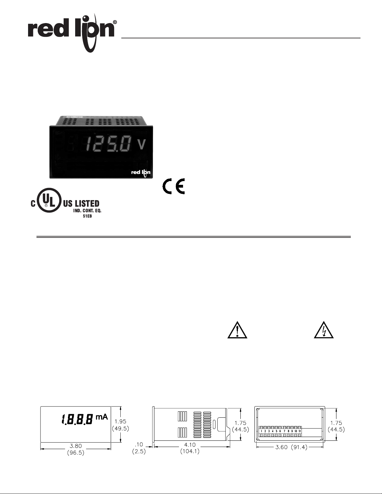
MODEL PAXLCL - PAX LITE CURRENT LOOP METER
DIMENSIONS In inches (mm)
Note: Recommended minimum clearance (behind the panel) for mounting clip installation is
2.1" (53.4) H x 5.0" (127) W.
Bulletin No. PAXLCL-C
Drawing No. LP0567
Released 10/08
Tel +1 (717) 767-6511
Fax +1 (717) 764-0839
www.redlion.net
CAUTION: Read complete
instructions prior to installation
and operation of the unit.
CAUTION: Risk of electric shock.
C
US LISTEDUS
LISTED
U
L
R
IND. CONT. EQ.
51EB
Page 2
2
Ordering Information . . . . . . . . . . . . . . . . . . . 2
General Meter Specifications. . . . . . . . . . . . . 3
Accessories . . . . . . . . . . . . . . . . . . . . . . . . . 3
Installing the Meter . . . . . . . . . . . . . . . . . . . . 4
Setting the Switches . . . . . . . . . . . . . . . . . . . 4
Wiring the Meter . . . . . . . . . . . . . . . . . . . . . . 4
Scaling the Meter . . . . . . . . . . . . . . . . . . . . . 6
Calibrating the Meter. . . . . . . . . . . . . . . . . . . 7
Applications . . . . . . . . . . . . . . . . . . . . . . . . . 8
TABLE OF CONTENTS
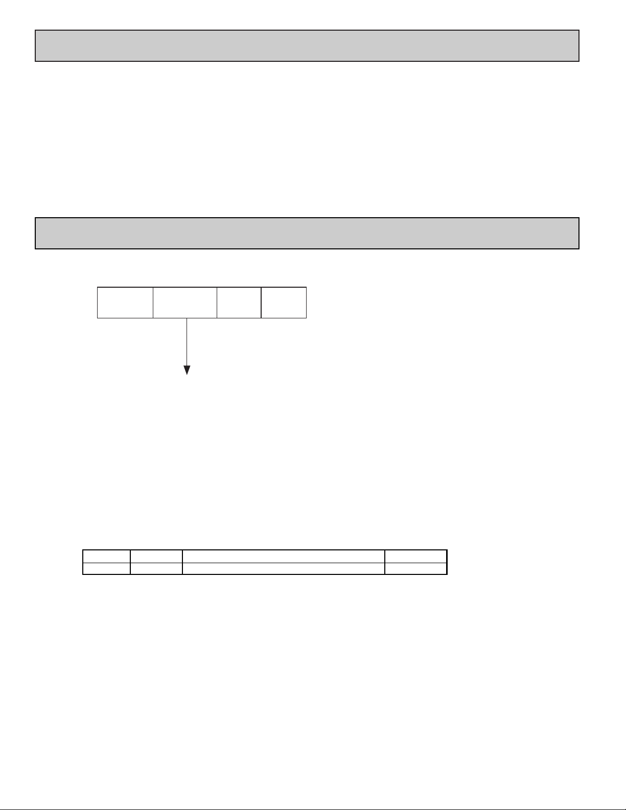
ORDERING INFORMATION
Meter Part Numbers
Accessories Part Numbers
PAXLBK30Units Label Kit Accessory PAXLBK
Accessories
TYPE PART NUMBERSDESCRIPTIONMODEL NO.
PAXL
CL
0
0
CL - Current Loop Meter
Page 3

1. DISPLAY: 3 1/2-digit, 0.56" (14.2 mm) high, 7-segment LED, (-) minus sign
displayed when current or voltage is negative. Decimal points inserted before
1st, 2nd, or 3rd least significant digits by DIP switch selection.
2. OVER-RANGE INDICATION: Indicated by blanking 3 least significant
digits.
3. POWER:
AC Power: 85 to 250 VAC, 50/60 HZ, 6 VA
Isolation: 2300 Vrms for 1 min. between input and supply (300 V working
voltage).
4. INPUT SENSITIVITY: (Numerical Readout Change/mA)
260 units/mA @ 4 to 20 mA input
105 units/mA @ 10 to 50 mA input
(max. allowable input current, 170 mA)
5. COMPLIANCE: Voltage drop across input at max. signal current, less than
600 mV for both 4 to 20 and 10 to 50 mA ranges.
6. INPUT RESISTANCE:
4 to 20 mA - 29.2 Ω
10 to 50 mA - 11.8 Ω
7. SCALING RANGE:
SPAN: 32 coarse steps (binary progression with 5 DIP switches) Each step
providing approx. 8.125 numerical units/mA/step sensitivity for 4 to 20
mA input and 3.25 units/mA/step for 10 to 50 mA input.
OFFSET: 16 coarse steps (binary progression with 4 DIP switches) with ±
switch to add or subtract offset. Each step adds or subtracts approximately
175 from the numerical display for a total offset range of ±2700.
8. LINEARITY: ±(0.05% ±1 digit)
9. READING RATE: 2.5 updated readings/second, nominal.
10. RESPONSE TIME: 1 second to settle for step change.
11. LOW FREQUENCY NOISE REJECTION:
Normal Mode Rejection: 63 dB @ 50/60 Hz
Common Mode Rejection: 100 dB, DC to 50/60 Hz
12. ENVIRONMENTAL CONDITIONS:
Operating Temperature: 0° to 60°C
Storage Temperature: -40° to 80°C
Operating and Storage Humidity: 85% max. relative humidity (non-
condensing)
Span Temperature Coeff.: 100 PPM/°C
Offset Temperature Coeff.: 100 PPM/°C
Vibration According to IEC 68-2-6: Operational 5 to 150 Hz, in X, Y, Z
direction for 1.5 hours, 2g’s.
Shock According to IEC 68-2-27: Operational 30g’s (10g relay), 11 msec in
3 directions.
Altitude: Up to 2000 meters
13. CERTIFICATIONS AND COMPLIANCES:
SAFETY
UL Recognized Component, File # E179259, UL61010A-1, CSA C22.2 No. 61010-1
Recognized to U.S. and Canadian requirements under the Component
Recognition Program of Underwriters Laboratories, Inc.
UL Listed, File # E137808, UL508, CSA C22.2 No. 14-M95
LISTED by Und. Lab. Inc. to U.S. and Canadian safety standards
Type 4X Enclosure rating (Face only), UL50
IECEE CB Scheme Test Certificate # US/8843A/UL
CB Scheme Test Report # 04ME11209-20041018
Issued by Underwriters Laboratories, Inc.
IEC 61010-1, EN 61010-1: Safety requirements for electrical equipment
for measurement, control, and laboratory use, Part 1.
IP65 Enclosure rating (Face only), IEC 529
IP20 Enclosure rating (Rear of unit), IEC 529
ELECTROMAGNETIC COMPATIBILITY
Emissions and Immunity to EN 61326: Electrical Equipment for
Measurement, Control and Laboratory use.
Notes:
1. Criterion A: Normal operation within specified limits.
2. Criterion B: Temporary loss of performance from which the unit self-
recovers.
14. EXCITATION SUPPLY: 24 VDC @ 50 mA max. Regulated and isolated.
15. CONNECTIONS: High compression cage-clamp terminal block
Wire Strip Length: 0.3" (7.5 mm)
Wire Gage: 30-14 AWG copper wire
Torque: 4.5 inch-lbs (0.51 N-m) max.
16. CONSTRUCTION: This unit is rated for NEMA 4X/IP65 use. IP20 Touch
safe. Installation Category II, Pollution Degree 2. One piece bezel/case.
Flame resistant. Panel gasket and mounting clip included.
17. WEIGHT: 0.65 lbs (0.24 kg)
3
GENERAL METER SPECIFICATIONS
ACCESSORIES
UNITS LABEL KIT (PAXLBK)
Each meter has a units indicator with backlighting that can be customized using
the Units Label Kit (PAXLBK30). The backlight is controlled by a DIP switch.
Class BEN 55011Emissions
Emissions:
0.5 cycle
Criterion AEN 61000-4-11Voltage dip/interruptions
30 A/m
Criterion AEN 61000-4-8Power frequency magnetic fields
3 V/rms
Criterion AEN 61000-4-6RF conducted interference
1 kV signal
1 kV L-L,
Criterion AEN 61000-4-5Surge
2 kV signal
2 kV power
Criterion AEN 61000-4-4Fast transients (burst)
2 kV L&N-E power
10 V/m
Criterion BEN 61000-4-3Electromagnetic RF fields
8 kV air discharge
4 kV contact discharge
Criterion AEN 61000-4-2Electrostatic discharge
Immunity:
Page 4

The meter has switches, which must be checked and/or changed prior to
applying power. To access the switches, remove the meter base from the case by
firmly squeezing and pulling back on the side rear finger tabs. This should lower
the latch below the case slot (which is located just in front of the finger tabs). It
is recommended to release the latch on one side, then start the other side latch.
Set-Up DIP Switches
Two banks of DIP switches are located inside the meter. The 10 position bank
of switches are used for calibrating the meter. The values of these switches are
discussed in section 5.0 Calibrating the Meter.
The bank of 4 switches located near the front display are used for the
selection of decimal points and backlight annunciator. Selecting “ON” position
enables the function.
4
2.0 SETTING THE SWITCHES
3.0 WIRING THE METER
1.0 INSTALLING THE METER
Installation
The PAX meets NEMA 4X/IP65 requirements when properly installed. The
unit is intended to be mounted into an enclosed panel. Prepare the panel cutout
to the dimensions shown. Remove the panel latch from the unit. Slide the panel
gasket over the rear of the unit to the back of
the bezel. The unit should be installed
fully assembled. Insert the unit into
the panel cutout.
While holding the unit in place, push the panel latch over the rear of the unit
so that the tabs of the panel latch engage in the slots on the case. The panel latch
should be engaged in the farthest forward slot possible. To achieve a proper seal,
tighten the latch screws evenly until the unit is snug in the panel (Torque to
approximately 7 in-lbs [79N-cm]). Do not over-tighten the screws.
Installation Environment
The unit should be installed in a location that does not exceed the maximum
operating temperature and provides good air circulation. Placing the unit near
devices that generate excessive heat should be avoided.
The bezel should be cleaned only with a soft cloth and neutral soap product.
Do NOT use solvents. Continuous exposure to direct sunlight may accelerate the
aging process of the bezel.
PANEL CUT-OUT
WIRING OVERVIEW
Electrical connections are made via screw-clamp terminals located on the
back of the meter. All conductors should conform to the meter’s voltage and
current ratings. All cabling should conform to appropriate standards of good
installation, local codes and regulations. It is recommended that power supplied
to the meter (AC) be protected by a fuse or circuit breaker.
When wiring the meter, compare the numbers embossed on the back of the
meter case against those shown in wiring drawings for proper wire position. Strip
the wire, leaving approximately 0.3" (7.5 mm) bare lead exposed (stranded wires
should be tinned with solder). Insert the lead under the correct screw-clamp
terminal and tighten until the wire is secure. (Pull wire to verify tightness.)
Main
Circuit
Board
D.P./ BACKLIGHT
REAR TERMINALS
FRONT DISPLAY
4
3
2
1
ON
OFFSET
SPAN
ON
1
2
3
4
5
6
7
8
9
10
OFFSET
SPAN
Backlight Annunciator for Units Label4
Decimal Point 3 (0.000)3
Decimal Point 2 (00.00)2
Decimal Point 1 (000.0)1
FUNCTIONSWITCH
Page 5

5
3.2 INPUT SIGNAL WIRING
2-WIRE, EXTERNAL EXCITATION
2-WIRE, WITH EXCITATION (Series Conn.) 2-WIRE, WITH EXCITATION (Parallel Conn.)
NOTES
1. When shielded wire leads are used, connect the shield to earth ground at the meter and insulate the other end to avoid contact with machine ground.
2. Never run signal leads in conduit, bundles, or race ways with power conductors. Avoid runs close to contactors, relays, solenoids, transformers, and other potential
sources of electrical noise.
EMC INSTALLATION GUIDELINES
Although this meter is designed with a high degree of immunity to ElectroMagnetic Interference (EMI), proper installation and wiring methods must be
followed to ensure compatibility in each application. The type of the electrical
noise, its source or the method of coupling into the unit may be different for
various installations. Listed below are some EMC guidelines for successful
installation in an industrial environment.
1. The meter should be mounted in a metal enclosure, which is properly
connected to protective earth.
2. Never run Signal or Control cables in the same conduit or raceway with AC
power lines, conductors feeding motors, solenoids, SCR controls, and
heaters, etc. The cables should be run in metal conduit that is properly
grounded. This is especially useful in applications where cable runs are long
and portable two-way radios are used in close proximity or if the installation
is near a commercial radio transmitter.
3. Signal or Control cables within an enclosure should be routed as far away as
possible from contactors, control relays, transformers, and other noisy
components.
4. In extremely high EMI environments, the use of external EMI suppression
devices, such as ferrite suppression cores, is effective. Install them on Signal
and Control cables as close to the unit as possible. Loop the cable through the
core several times or use multiple cores on each cable for additional protection.
Install line filters on the power input cable to the unit to suppress power line
interference. Install them near the power entry point of the enclosure. The
following EMI suppression devices (or equivalent) are recommended:
Ferrite Suppression Cores for signal and control cables:
Fair-Rite # 0443167251 (RLC #FCOR0000)
TDK # ZCAT3035-1330A
Steward #28B2029-0A0
Line Filters for input power cables:
Schaffner # FN610-1/07 (RLC #LFIL0000)
Schaffner # FN670-1.8/07
Corcom #1VR3
Note: Reference manufacturer’s instructions when installing a line filter.
5. Long cable runs are more susceptible to EMI pickup than short cable runs.
Therefore, keep cable runs as short as possible.
6. Switching of inductive loads produces high EMI. Use of snubbers across
inductive loads suppresses EMI.
Snubber: RLC#SNUB0000.
3.1 POWER WIRING
AC Power
Terminal 1: VAC
Terminal 2: VAC
Page 6

6
DESCRIPTION OF OPERATION
The PAX Lite Current Loop Meter consists of a digital volt meter combined
with an analog scaling circuit (shown above). The unit was designed primarily for
use with 4-20 mA and 10-50 mA current loop signal circuits. However, it can also
be adapted to other current ranges, such as 0-50 mA, 0-20 mA, 0-10 mA, and in
a great many applications it can be used even with 0-5 mA and 1-5 mA current
loops. In addition, input current can be reversed in polarity resulting in negative
numerical readout with a minus (-) sign displayed. Input terminals 3 and 4 are
connected in series with 10-50 mA current loops, and Terminal 3 and 5 are series
connected with 4-20 mA loops. In either case, the voltage drop generated across
the shunt resistor(s) ranges from approximately 0.12 V min. (@ 4 or 10 mA) to
0.59 V max. (@ 20 or 50 mA). The buffer amplifier (K1) conditions and filters
the input signal voltage and applies it to the input of the scaling circuit. The
procedure for scaling PAX Lite Current Loop Meters is simplified by dividing the
scaling process into two separate components, span adjustments and offset
adjustments which are defined in the following discussion.
SPAN ADJUSTMENTS
Span is defined as the numerical range that the display traverses, disregarding
decimal points, when the input signal current is varied from minimum (4 or 10
mA) to maximum (20 or 50 mA). For example, if a unit is to display 25.0 @ 4
mA and 100.0 @ 20 mA, the span is 750 (the difference between 250 and 1000).
Had the minimum display been -25.0 @ 4 mA and +100.0 @ 20 mA, the span
would be 1250 (1000 - (-250) = 1250). (Note: the terms “GAIN”, “SCALE”, and
“SENSITIVITY” are also frequently used interchangeably with the term
“SPAN.”) The PAX Lite Current Loop Meter
can be set up over a very wide span range by
means of the coarse DIP switches S6-S10, and
the fine screwdriver adjustment pot, located at
the back cover. The coarse span switches add
parallel input resistors to the summing
amplifier (K2), thereby increasing its gain, or
sensitivity, as more summing resistors are
added. Effectively, adding more parallel input
resistors, increases the slope of the transfer
curve (at right) and increases the numerical
readout for a given input signal current change. The input summing resistor values
are weighted in a binary progression, so they can be switched in combinations to
give 32 discrete steps of span. The fine adjust control brackets these coarse steps
and can be adjusted to the exact span needed.
The approximate span contributed by each switch is shown on the rear label.
These values are based on the standard current-loop spans of 4 to 20 mA (16 mA
current variation) and 10-50 mA (40 mA current variation). In other words, if S7
only is turned “ON”, the numerical readout will display a change approximately
1050 for a current swing of 16 mA (4-20 mA input) or 40 mA (10-50 mA input).
If S8 were also turned “ON”, the numerical readout would swing approximately
1575 (1050 for S7 + 525 for S8) for the same signal current variation. The fine
control has a continuous span range of approximately 0-150.
OFFSET ADJUSTMENTS
In the foregoing discussion of span, the transfer curves were shown as
“ZERO-BASED”, i.e., the numerical readout displays “0” when the signal
current goes to zero. With current loop ranges such as 0-5 or 0-10, or 0-20 mA,
and with Bi-Polar (+/-) signals, this is often the desired condition. However,
with 4-20 and 10-50 mA current loops, the minimum current level of 4 or 10
mA usually represents the zero level of the parameter being displayed. There are
also many applications where the minimum
(or zero level) represents some value that
does not fall on a zero based transfer curve.
To accommodate non-zero based
applications, the PAX Lite Current Loop
Meter has provisions for offsetting the
transfer curve over a wide range.
Essentially, offset moves the transfer curve
up or down to change its intercept with the
numerical readout axis, but it does not
change the slope (SPAN) of the transfer
curve. In the PAX Lite Current Loop Meter,
offset is accomplished by adding (or
subtracting) a constant at the input of the summing amplifier (K2). This offset
constant is summed in with a switched binary resistor network and a fine adjust
offset control in a similar manner to that used for span adjustment. Switches S2S5 can be turned on in combinations to give 16 different coarse offset levels.
Each switch is labeled to show the approximate amount of offset contributed
when it is turned “ON”. Switch 1 selects the polarity of the switched-in offset
value and allows offsetting the transfer curve “UP” (adding the offset constant)
or “DOWN” (subtracting). The fine offset control has a numerical readout range
of ±100 and brackets all the coarse switched ranges.
PAXLCL SCHEMATIC
4.0 SCALING THE METER
Page 7

7
5.0 CALIBRATING THE METER
Direct calibration in the signal loop is usually not practical due to the
difficulty in varying the measured parameter and the confusing interaction that
occurs between span and offset adjustments. However, the PAXLCL can be
quickly and easily bench calibrated using a commercially available current
calibrator or the calibration set-up shown below.
CALIBRATION PROCEDURE
The procedure outlined below minimizes span/offset interaction and
simplifies calibration. In Steps 1 to 4 the unit is “nulled” to zero readout with
zero input signal current. In Steps 5 and 6, the span adjustments are made to
establish the required slope of the transfer curve. Then in Step 7, the transfer
curve is shifted up or down as required by setting the offset adjustments. In Step
8, the final “tweaking” adjustments are made at minimum and maximum signal
current. Setting the decimal points in Step 9 completes the calibration.
Before calibrating, the READOUT SPAN (Rs) and SWING CURRENT (Is)
must be determined.
WHERE:
Rs = (Max. Numerical Display) - (Min. Numerical Display) (Disregard Decimal Points)
Is = (Current @ Max. Display) - (Current @ Min. Display)
Example:
Readout is to be 0.00 @ 4 mA and 10.00 @ 20 mA.
READOUT SPAN (Rs) = 1000 - 0 = 1000
SWING CURRENT (Is) = 20 mA - 4 mA = 16
CALIBRATION STEPS
1. Power down the meter and remove it from its case. Turn off all offset and
span adjustment switches (S2-S10 down). S1 has no effect when zeroing
and can be in either position.
2. Turn the span control pot fully counter-clockwise (20 turns max.).
3. Turn on a combination of span adjust switches (6-10) to obtain a total value
closest to (but not greater than) the READOUT SPAN (Rs) desired (1000
in this example). The following chart gives an approximate span
adjustment value for each switch:
4. Place unit in its case and apply power. Apply zero current. Adjust the
indicator to read zero using the offset adjustment pot.
5. Apply the SWING CURRENT (Is) (16 mA in the example) to the input.
Set the exact READOUT SPAN value (1000) with span adj.pot.
6. Apply zero current to see if the zero value has shifted. If it has, re-zero with
the offset pot, then repeat Step 5.
7. After the span has been adjusted, set the signal current to the minimum
level (4 mA in the example). Record the meter reading (in this example the
reading will be 250). Subtract the desired reading at minimum current
value (0 in the example) from the recorded reading (0-250 = - 250). Power
down the meter and remove it from its case. Set the offset add/subtract
switch S1 (subtract = on), and the offset switches (S2-S5) to obtain a total
value closest to (but no more than) the difference between the desired
reading at minimum current value and the observed reading The following
chart gives an approximate offset adjustment value for each switch:
Place the meter in its case and apply power. Using the offset adjust pot,
adjust the readout to equal the desired reading at the minimum current
value (0 in the example).
8. Adjust the input signal current to its maximum value to see if the proper
readout is obtained (1000 @ 20 mA in the example). If the readout is
slightly off, adjust the span pot to obtain the true reading. Then, recheck
the reading at the minimum input current (4 mA) and readjust the offset
pot if necessary. Repeat the maximum and minimum readout adjustments
until the unit displays the proper readout at both extremes.
9. Set decimal points as desired using the three decimal point switches. The
unit can now be installed.
TROUBLESHOOTING
For further assistance, contact technical support at the appropriate company
numbers listed.
SWITCH NUMBER SPAN VALUE
6 2100
7 1050
8 525
9 260
10 130
1755
3504
7003
14002
OFFSET VALUESWITCH NUMBER
LIMITED WARRANTY
The Company warrants the products it manufactures against defects in materials and workmanship
for a period limited to one year from the date of shipment, provided the products have been stored,
handled, installed, and used under proper conditions. The Company’s liability under this limited
warranty shall extend only to the repair or replacement of a defective product, at The Company’s
option. The Company disclaims all liability for any affirmation, promise or representation with
respect to the products.
The customer agrees to hold Red Lion Controls harmless from, defend, and indemnify RLC against
damages, claims, and expenses arising out of subsequent sales of RLC products or products
containing components manufactured by RLC and based upon personal injuries, deaths, property
damage, lost profits, and other matters which Buyer, its employees, or sub-contractors are or may be
to any extent liable, including without limitation penalties imposed by the Consumer Product Safety
Act (P.L. 92-573) and liability imposed upon any person pursuant to the Magnuson-Moss Warranty
Act (P.L. 93-637), as now in effect or as amended hereafter.
No warranties expressed or implied are created with respect to The Company’s products except those
expressly contained herein. The Customer acknowledges the disclaimers and limitations contained
herein and relies on no other warranties or affirmations.
Page 8
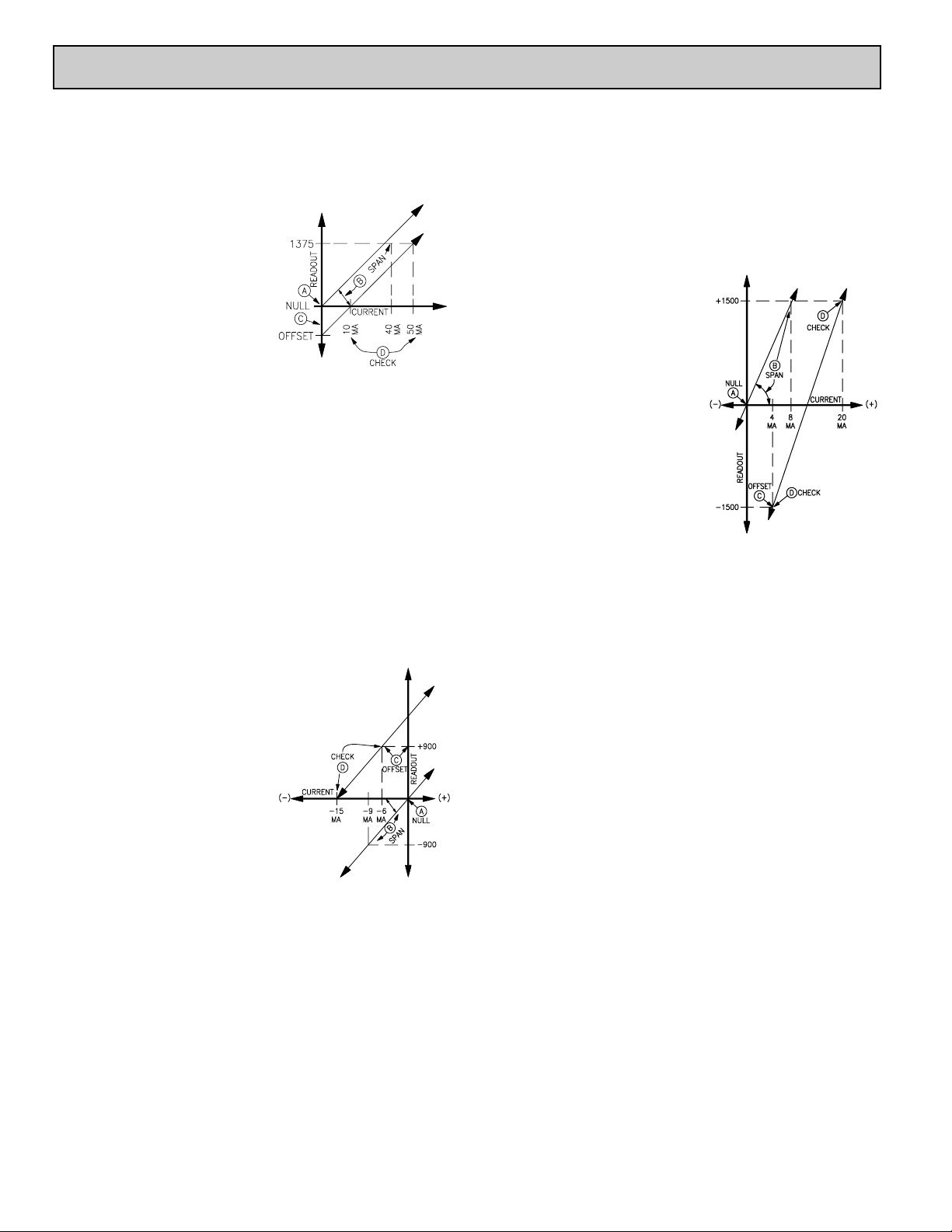
Example 1:
A PAXLCL is to be calibrated to match a flow transducer whose output is 10
mA @ 0 GPM and 50 mA @ 1375 GPM.
READOUT SPAN (Rs) = 1375 − 0 = 1375
SWING CURRENT (Is) = 50 mA − 10 mA = 40 mA
ADJUSTMENTS (Refer to the transfer curve below)
!
Null the unit to zero readout @ 0
current per Steps 1 to 4 of the
calibration steps.
"
Set the coarse and fine span adjustments
to get a readout of 1375 @ 40 mA per
Steps 5 and 6. Note: With the full
standard swing of 40 mA, the coarse
span switch reference markings can be
used to determine settings as follows:
S7 ON (1050) + S9 ON (260) = 1310
Span set with switches.
375 (needed) - 1310 (with SW’s) = 65
w. fine span adj.
#
Set offset to readout 0 @ 10 mA per Step 7. Note: The read out observed
when the 10 mA min. current is first applied can be used to determine the
offset switch settings.) In this example the readout will be (+) 344 when the
10 mA min. current is first applied. Applying -344 offset then reduces the
readout to zero @ 10 mA.
$
Check readout at max. (50 mA) and min. (10 mA) and fine tune (tweak) as
required per Step 8.
Example 2 (Negative Slope):
A level measuring device puts out 6 mA when a storage tank is full and 15
mA when the tank is empty. The PAXLCL is to readout 90.0 tons at full tank
and zero when empty.
READOUT SPAN (Rs) = 900 − 0 = 900 (Disregard Decimal Points)
SWING CURRENT (Is) = 6 mA (@ max rdg) - 15 mA (@ min rdg) = -9 mA
In this case, the signal current is reverse [Term 3 (-) with respect to Term 5
(+)] causing the readout to go “down” (increasingly negative) as the negative
current increases.
ADJUSTMENTS
!
Null the unit per Steps 1 to 4.
"
Set slope of transfer curve with span
adjustments to get readout of -900 @ 9 mA per Steps 5 and 6.
#
Move transfer curve up by applying
(+) offset per Step 7 until readout is
+900 @ -6 mA.
$
Check extreme readings per Step 8, 0
readout @ -15 mA and +900 readout
@ -6 mA. Set D.P. Switch S1 and
replace unit in case.
Example 3 (± Display):
A differential pressure transducer has a range of ±1500 PSI with a 4 to 20 mA
output (-1500 @ 4 mA, +1500 @ 20 mA).
READOUT SPAN (Rs) = +1500 −(−1500) = 3000
SWING CURRENT (Is) = 20 mA(max) - 4 mA(min) = 16 mA
Note: Since the display readout is limited to 1999 numerical indication, the
full READOUT SPAN of 3000 cannot be obtained during zero based span
adjustment. However, dividing both the READOUT SPAN and SWING
CURRENT by two, i.e. 1500 readout @ 8 mA, allows the span adjustment
to be made for the proper transfer curve slope.
ADJUSTMENTS
!
Null the unit per Steps 1 to 4.
"
Set transfer curve slope with span
adjustments per Steps 5 and 6, to get a
readout of +1500 @ 8 mA.
#
Apply (-) offset per Step 7 to get a
reading of -1500 @ 4 mA.
$
Check min. and max. extremes and
tweak if required to get desired readout
@ 4 and 20 mA per Step 8.
6.0 APPLICATIONS
Red Lion Controls
20 Willow Springs Circle
York PA 17406
Tel +1 (717) 767-6511
Fax +1 (717) 764-0839
Red Lion Controls AP
Unit 101, XinAn Plaza
Building 13, No.99 Tianzhou Road
ShangHai, P.R. China 200223
Tel +86 21 6113-3688
Fax +86 21 6113-3683
Red Lion Controls BV
Printerweg 10
NL - 3821 AD Amersfoort
Tel +31 (0) 334 723 225
Fax +31 (0) 334 893 793
 Loading...