

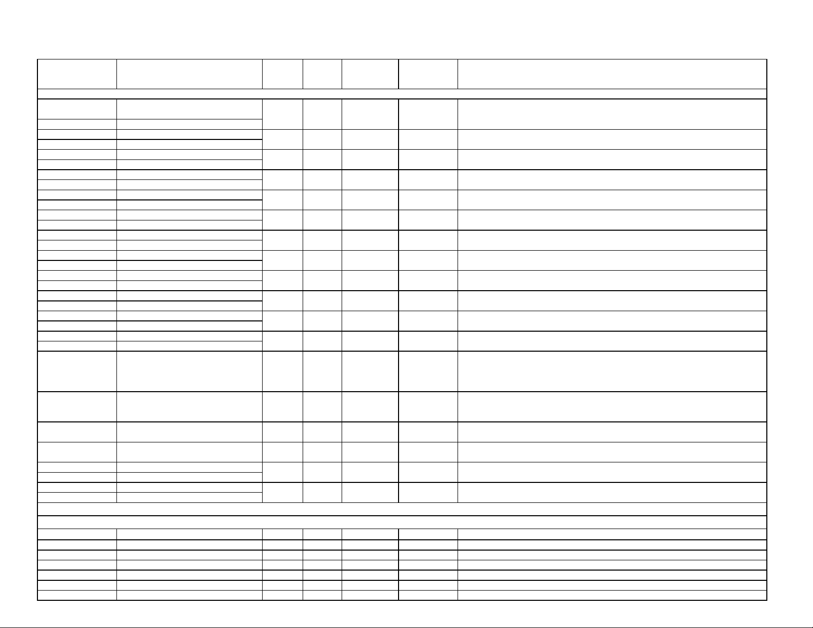
PAX2S Modbus Register Table
REVISED 2/20/12 LP0894A
REGISTER
ADDRESS
40001
40002
40003
40004
40005
40006
40007
40008
40009
40010
40011
40012
40013
40014
40015
40016
40017
40018
40019
40020
40021
40022
40023
40024
40025
40026
40027
40028
40029
40030
40031
40032
40081
40082
40083
40084
40085
40086
40087
REGISTER NAME
FREQUENTLY USED REGISTERS
Input Relative Value (Hi word)
Input Relative Value (Lo word)
Maximum Value (Hi word)
Maximum Value (Lo word)
Minimum Value (Hi word)
Minimum Value (Lo word)
Total Value (Hi word)
Total Value (Lo word)
Setpoint 1 Value (Hi word)
Setpoint 1 Value (Lo word)
Setpoint 2 Value (Hi word)
Setpoint 2 Value (Lo word)
Setpoint 3 Value (Hi word)
Setpoint 3 Value (Lo word)
Setpoint 4 Value (Hi word)
Setpoint 4 Value (Lo word)
Setpoint 1 Band/Dev. Value (Hi word)
Setpoint 1 Band/Dev. Value (Lo word)
Setpoint 2 Band/Dev. Value (Hi word)
Setpoint 2 Band/Dev. Value (Lo word)
Setpoint 3 Band/Dev. Value (Hi word)
Setpoint 3 Band/Dev. Value (Lo word)
Setpoint 4 Band/Dev. Value (Hi word)
Setpoint 4 Band/Dev. Value (Lo word)
Setpoint Output Register (SOR) 0 15 N/A Read/Write
Manual Mode Register (MMR) 0 31 0 Read/Write
Reset Output Register 0 15 0 Read/Write
Analog Output Register (AOR) 0 4095 0 Read/Write
Input Gross (Absolute) Value (Hi word)
Input Gross (Absolute) Value (Lo word)
Tare Value (Hi word)
Tare Value (Lo word)
INPUT PARAMETERS SEE INPUT MODULE FOR PARAMETER DESCRIPTIONS
Analog Input
Input Range 0 1 0 Read/Write 0 = +/-24mV, 1 = +/-240mV
ADC Conversion Rate (samples/sec)
Decimal Point
Rounding Factor
Digital Input Filter
Filter Band
Input Scaling Points in List Function
LOW
LIMIT
-199999 999999 N/A Read Only
-199999 999999 N/A Read/Write
-199999 999999 N/A Read/Write
-199999 999999 N/A Read/Write
-199999 999999 100 Read/Write
-199999
-199999 999999 300 Read/Write
-199999
-199999
-199999 999999 0
-199999
-199999 999999 N/A Read Only
-199999
0 5 0 Read/Write
0 4 2 Read/Write
0 6 0 Read/Write
0 2500 100 Read/Write
0 2500 10 Read/Write
0 1 0 Read/Write
HIGH
LIMIT
999999 200 Read/Write
999999 400 Read/Write
999999
999999
999999 0
FACTORY
SETTING
0
0 Read/Write
ACCESS COMMENTS
Read/Write-199999
Read/Write
Read/Write999999 0
Read/Write
Process value of present input level. This value is affected by Input Type,
Resolution, Scaling, & Tare (Offset) Value.
(Relative Value = Gross (Absolute) Input Value - Tare Value)
1 = 1 display unit
1 = 1 display unit
1 = 1 display unit
Active List (A or B)
Active List (A or B)
Active List (A or B)
Active List (A or B)
Active List (A or B).
Applicable only for Band or Deviation Setpoint Action.
Active List (A or B).
Applicable only for Band or Deviation Setpoint Action.
Active List (A or B).
Applicable only for Band or Deviation Setpoint Action.
Active List (A or B).
Applicable only for Band or Deviation Setpoint Action.
Status of Setpoint Outputs. Bit State: 0=Off, 1=On.
Bit 3 = SP1, Bit 2 = SP2, Bit 1 = SP3, Bit 0 = SP4.
Outputs can only be activated/ reset with this register when the respective bits in t he
Manual Mode Register (MMR) are set.
Bit State: 0=Auto Mode, 1=Manual Mode
Bit 4 = SP1, Bit 3 = SP2, Bit 2 = SP3, Bit 1 = SP4,
Bit 0 = Linear Output
Bit State: 1= Reset Output, bit is returned to zero following reset processing; Bit 3 =
SP1, Bit 2 = SP2, Bit 1 = SP3, Bit 0 = SP4
Functional only if Linear Output is in Manual Mode.(MMR bit 0 = 1)
Linear Output Card written to only if Linear Out (MMR bit 0) is set.
Gross (absolute) value of present Input level. This value is affected by Input Ty pe,
Resolution, Scaling, but not affected by Offset Value
Relative Input Value (standard meter value) is the difference between t he Gross
(absolute) input value and the Tare value, i.e. Relative = Gr oss - Tare
0 = 5, 1 = 10, 2 = 20, 3 = 40, 4 = 80, 5 = 160
0 = 0, 1 = 0.0, 2 = 0.00, 3 = 0.000, 4 = 0. 0000
0 = 1, 1 = 2, 2 = 5, 3 = 10, 4 = 20, 5 = 50, 6 = 100
1 = 0.01 Second
1 = 1 display unit
0 = No, 1 = Yes
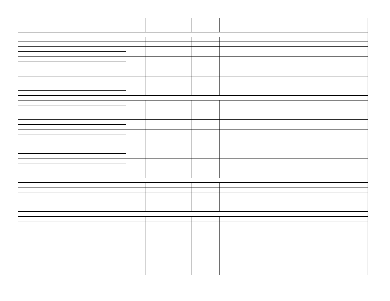
REGISTER
A
A
A
ADDRESS
List
40101 40201 Number of Scaling Points
40102 40202 Reserved
40103 40203 Scaling Pt.1 Input Value (Hi word)
40104 40204 Scaling Pt.1 Input Value (Lo word)
40105 40205 Scaling Pt.1 Display Value (Hi word)
40106 40206 Scaling Pt.1 Display Value (Lo word)
thru thru Scaling Pts. 2 thru 15 Values … … … …
40163 40263 Scaling Pt.16 Input Value (Hi word)
40164 40264 Scaling Pt.16 Input Value (Lo word)
40165 40265 Scaling Pt.16 Display Value (Hi word)
40166 40266 Scaling Pt.16 Display Value (Lo word)
List
40167 40267 Setpoint 1 Value (Hi word)
40168 40268 Setpoint 1 Value (Lo word)
40169 40269 Setpoint 2 Value (Hi word)
40170 40270 Setpoint 2 Value (Lo word)
40171 40271 Setpoint 3 Value (Hi word)
40172 40272 Setpoint 3 Value (Lo word)
40173 40273 Setpoint 4 Value (Hi word)
40174 40274 Setpoint 4 Value (Lo word)
40175 40275 Setpoint 1 Band/Dev. Value (Hi word)
40176 40276 Setpoint 1 Band/Dev. Value (Lo word)
40177 40277 Setpoint 2 Band/Dev. Value (Hi word)
40178 40278 Setpoint 2 Band/Dev. Value (Lo word)
40179 40279 Setpoint 3 Band/Dev. Value (Hi word)
40180 40280 Setpoint 3 Band/Dev. Value (Lo word)
40181 40281 Setpoint 4 Band/Dev. Value (Hi word)
40182 40282 Setpoint 4 Band/Dev. Value (Lo word)
List
40183 40283 Input Decimal Point
40184 40284 Input Rounding Factor
40185 40285 Input Filter Band
40186 40286 Auto-Zero Tracking Band
40187 40287 Totalizer Decimal Point
40188 40288 Totalizer Scale Factor
List B Analog Input Scaling Points Parameters
List B Setpoint Values
List B Scaling Parameters
User Input / Function Keys
40301
40303
40304
User Input Active State
User Input 2 Action
User Input 3 Action
REGISTER NAME
LOW
LIMIT
2 16 2 Read/Write
N/A N/A N/A N/A
-199999 999999 0 Read/Write
-199999 999999
-199999
-199999
-199999 999999 Read/Write100 1 = 1 display unit
-199999 999999
-199999 999999 300 Read/Write
-199999 999999
-199999 999999 0 Read/Write
-199999 999999 0 Read/Write Applicable only for Band or Deviation Setpoint Action.
-199999 999999 0 Read/Write
-199999 999999 0 Read/Write
0 4 2 Read/Write
0 6 0 Read/Write
0 2500 10 Read/Write
0 4095 2 Read/Write
0 4 3 Read/Write
1 65000 1000 Read/Write
0 1 0 Read/Write
0 30 0 Read/Write
0 30 0 Read/Write
HIGH
LIMIT
999999
999999
FACTORY
SETTING
0
0 Read/Write
200
400
0
ACCESS COMMENTS
Read/Write
Read/Write
Read/Write 1 = 1 display unit
Read/Write40302 User Input 1 Action 0 30
Number of Linearization Scaling Points
1 = 0.001
1 = 1 display unit
Registers 40107-40162 and 40207-40262 hold values for Scaling Points 2 thru 15,
and follow the same ordering as Scaling Point 1.
1 = 1 display unit
1 = 1 display unitRead/Write0
1 = 1 display unit
1 = 1 display unit
Applicable only for Band or Deviation Setpoint Action.
Applicable only for Band or Deviation Setpoint Action.
Applicable only for Band or Deviation Setpoint Action.
0 = 0, 1 = 0.0, 2 = 0.00, 3 = 0.000, 4 = 0. 0000
0 = 1, 1 = 2, 2 = 5, 3 = 10, 4 = 20, 5 = 50, 6 = 100
1 = 1 display unit
0 = OFF, 1 = display unit
0 = 0, 1 = 0.0, 2 = 0.00, 3 = 0.000, 4 = 0. 0000
1 = 0.001
0 = Active Low, 1 = Active High
0 = NO 9 = d-tot 18 = Sel L1 27 = r-34
1 = PLOC 10 = r-tot1 19 = Sel L2 28 = r-234
2 = rEL 11 = r-tot2 20 = d-LEV 29 = r-ALL
3 = r-TArE 12 = E-tot 21 = Color 30 = Print
4 = d-rEL 13 = d-HI 22 = LISt
5 = d-HLd 14 = r-HI 23 = r-1
6 = A-HLd 15 = d-Lo 24 = r-2
7 = SYNC 16 = r-Lo 25 = r-3
8 = bAt 17 = r-HL 26 = r-4
Same as User Input 1 Action
Same as User Input 1 Action
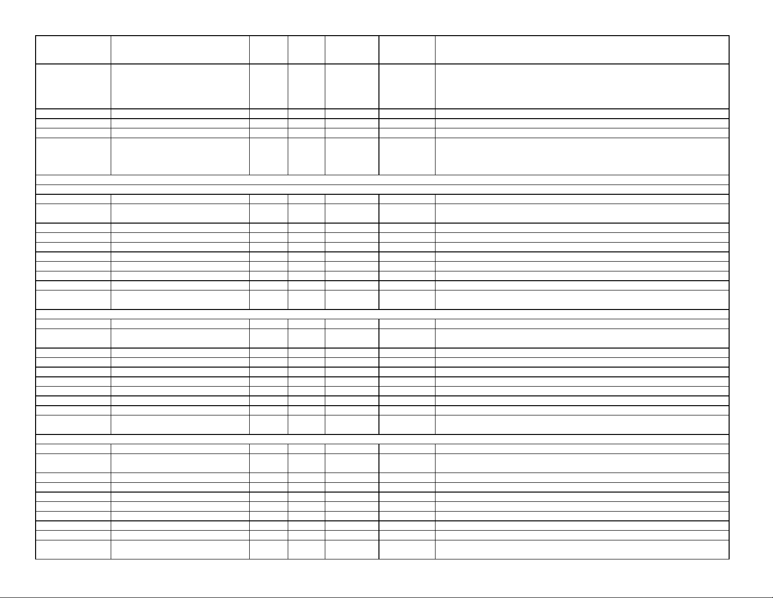
REGISTER
ADDRESS
40306
40307
40308
40309
40401
40402
40403
40404
40405
40406
40407
40408
40409
40410
40421
40422
40423
40424
40425
40426
40427
40428
40429
40430
40441
40442
40443
40444
40445
40446
40447
40448
40449
40450
REGISTER NAME
User F2 Key Action
User F1 Second Action
User F2 Second Action
User List Assign 0 3 0 Read/Write
OUTPUT PARAMETERS SEE OUTPUT MODULE FOR PARAMETER DESCRIPTIONS
Setpoint 1
Assignment
Action 0 10 0 Read/Write
Hysteresis Value
On Time Delay
Off Time Delay
Output Logic
Reset Action
Standby Operation
Annunciator
Color 0 7 0 Read/Write
Setpoint 2
Assignment
Action 0 10 0 Read/Write
Hysteresis Value
On Time Delay
Off Time Delay
Output Logic
Reset Action
Standby Operation
Annunciator
Color 0 7 0 Read/Write
Setpoint 3
Assignment
Action 0 10 0 Read/Write
Hysteresis Value
On Time Delay
Off Time Delay
Output Logic
Reset Action
Standby Operation
Annunciator
Color 0 7 0 Read/Write
LOW
LIMIT
0 20 0 Read/Write
0 20 0 Read/Write
0 20 0 Read/Write
0 3 0 Read/Write
1 65000 2 Read/Write
0 32750 0 Read/Write
0 32750 0 Read/Write
0 1 0 Read/Write
0 2 0 Read/Write
0 1 0 Read/Write
0 3 1 Read/Write
0 3 0 Read/Write
1 65000 2 Read/Write
0 32750 0 Read/Write
0 32750 0 Read/Write
0 1 0 Read/Write
0 2 0 Read/Write
0 1 0 Read/Write
0 3 1 Read/Write
0 3 0 Read/Write
1 65000 2 Read/Write
0 32750 0 Read/Write
0 32750 0 Read/Write
0 1 0 Read/Write
0 2 0 Read/Write
0 1 0 Read/Write
0 3 1 Read/Write
HIGH
LIMIT
FACTORY
SETTING
ACCESS COMMENTS
0 = NO 5 = r-tot 10 = SEL L2 15 = r-3 20 = Print
Read/Write0200User F1 Key Action40305
1 = rEL 6 = r-HI 11 = d-LEV 16 = r-4
2 = r-TArE 7 = r-Lo 12 = LISt 17 = r-34
3 = d-rEL 8 = r-HL 13 = r-1 18 = r-234
4 = bAt 9 = SEL L1 14 = r-2 19 = r-ALL
Same as User F1 Key Action
Same as User F1 Key Action
Same as User F1 Key Action
Set bits to enable items in List A/B parameter list.
Bit 0: Scaling (Scaling Points, Input Decimal Point, Input Rounding Factor, Input
Filter Band, Auto-Zero Tracking Band, Total Decimal Point , Total Scale Factor;
Bit 1: Units Mnemonics
0 = None, 1 = Rel, 2 = Gross, 3 = Total
0=No, 1=Ab-HI, 2=Ab-LO, 3=AU-HI, 4=AU-LO, 5=dE-HI, 6=dE-LO, 7=bANd,
8=bNdIn, 9=totLo, 10=totHi
1 = 1 Display Unit
1 = 0.1 Second
1 = 0.1 Second
0 = Normal, 1 = Reverse
0 = Auto, 1 = Latch1, 2 = Latch2
0 = No, 1 = Yes
0 = Off, 1 = Normal, 2 = Reverse, 3 = Flash
0 = No Change, 1 = Green, 2 = Orange, 3 = Red, 4 = Gr n/Org,
5 = Red/Org, 6 = Red/Grn, 7 = Line 1 Color

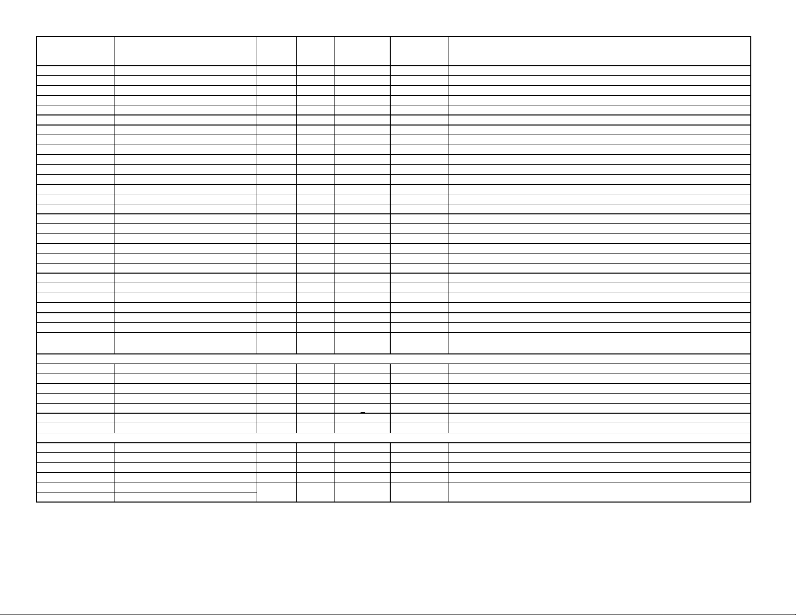
REGISTER
ADDRESS
40461
40462
40463
40464
40465
40466
40467
40468
40469
40470
40491
40492
40493
40494
40495
40496
40497
40331
40332
40333
40334
40335
40336
40337
40338
40339
40340
40341
40342
40343
40344
40345
40346
40347
40348
40349
REGISTER NAME
Setpoint 4
Assignment
Action 0 10 0 Read/Write
Hysteresis Value
On Time Delay
Off Time Delay
Output Logic
Reset Action
Standby Operation
Annunciator
Color 0 7 0 Read/Write
Analog O utput Parameters
Type
Assignment 0 9 0 Read/Write
Analog Low Scale Value (Hi word)
Analog Low Scale Value (Lo word)
Analog High Scale Value (Hi word)
Analog High Scale Value (Lo word)
Update time
DISPLAY PARAMETERS SEE DISPLAY MODULE FOR PARAMETER DESCRIPTIONS
Line 1 Parameters
Line 1 Display Color
Display Intensity Level
Display Contrast Level
Line 1 Display Value Enable 1 0 255 1 Read/Write
Line 1 Display Value Enable 2 0 3 1 Read/Write
Line 1 Scroll Enable/Time
Line 1 Units Mode
Units Digit 1 (Left)
Units Digit 2 (Center)
Units Digit 3 (Right)
Line 2 Parameters
Line 2 Input Display Access
Line 2 Gross (Absolute) Display Access
Line 2 Tare (Offset) Display Access
Line 2 Totalizer Display Access
Line 2 Maximum (Hi) Value Access
Line 2 Minimum (Lo) Value Access
Line 2 List Selection Access
Line 2 Setpoint 1 Value Access
Line 2 S1 Band/Dev.Value Access
LOW
LIMIT
0 3 0 Read/Write
1 65000 2 Read/Write
0 32750 0 Read/Write
0 32750 0 Read/Write
0 1 0 Read/Write
0 2 0 Read/Write
0 1 0 Read/Write
0 3 1 Read/Write
0 2 1 Read/Write
-199999 Read/Write0
0 100 0 Read/Write
0 2 0 Read/Write
0 4 4 Read/Write
0 15 7 Read/Write
0 15 0 Read/Write
0 3 0 Read/Write
057 0
0 2 0 Read/Write
0 1 0 Read/Write
0 2 0 Read/Write
0 2 0 Read/Write
0 2 0 Read/Write
0 2 0 Read/Write
0 5 0 Read/Write
0 5 0 Read/Write
0 5 0 Read/Write
HIGH
LIMIT
999999
999999
FACTORY
SETTING
10000
ACCESS COMMENTS
0 = None, 1 = Rel, 2 = Gross, 3 = Total
0=No, 1=Ab-HI, 2=Ab-LO, 3=AU-HI, 4=AU-LO, 5=dE-HI, 6=dE-LO, 7=bANd,
8=bNdIn, 9=totLo, 10=totHi
1 = 1 Display Unit
1 = 0.1 Second
1 = 0.1 Second
0 = Normal, 1 = Reverse
0 = Auto, 1 = Latch1, 2 = Latch2
0 = No, 1 = Yes
0 = Off, 1 = Normal, 2 = Reverse, 3 = Flash
0 = No Change, 1 = Green, 2 = Orange, 3 = Red, 4 = Gr n/Org,
5 = Red/Org, 6 = Red/Grn, 7 = Line 1 Color
0 = 0-20 mA, 1 = 4-20 mA, 2 = 0-10 V
0=None, 1=Rel, 2=Gross, 3=Total, 4=HI, 5=LO, 6=S1, 7=S2, 8=S3, 9=S4
Display value that corresponds with 0 V, 0 mA or 4 mA output
Read/Write
Read/Write
Display value that corresponds with 10 V or 20 mA out put-199999
0 = Max update rate, 1 = 0.1 Second
0 = Green, 1 = Red, 2 = Orange
0 = Min.(off), 4 = Max.
0 = Max downward viewing angle, 15 = Max upward viewing angle
Bit State: 0 = No (Disabled), 1 = Yes (Enabled)
Bit 0 = Input, Bit 1 = Gross, Bit 2 = Tare, Bit 3 = Total, Bit 4 = Max, Bit 5 = Min, Bit 6 =
Setpoint 1, Bit 7 = Setpoint 2
Bit State: 0 = No (Disabled), 1 = Yes (Enabled)
Bit 0 = Setpoint 3, Bit 1 = Setpoint 4
0 = No Scroll, 1-15 = Scroll Time in Seconds
0 = Off, 1 = Label, 2 = Custom, 3 = Factory
Label Mnemonic Mode only. Active List (A or B).
0 = 9 = I 18 = Q 27 = Z 36 = 8 45 = m(r) 54 = ]
1 = A 10 = J 19 = R 28 = 0 37 = 9 46 = o 55 = /
2 = b 11 = K 20 = S 29 = 1 38 = a 47 = q 56 = º
3 = C 12 = L 21 = t 30 = 2 39 = c 48 = r 57 = _
4 = d 13 = M(l) 22 = U 31 = 3 40 = e 49 = u
5 = E 14 = M(r) 23 = V 32 = 4 41 = g 50 = w(r)
6 = F 15 = N 24 = W(l) 33 = 5 42 = h 51 = 7 = G 16 = O 25 = W(r) 34 = 6 43 = i 52 = =
8 = H 17 = P 26 = Y 35 = 7 44 = n 53 = [
0=LOC, 1=d-rEAd, 2=d-rSt
0=LOC, 1=d-rEAd,
0=LOC, 1=d-rEAd, 2=d-Entr
0=LOC, 1=d-rEAd, 2=d-rSt
0=LOC, 1=d-rEAd, 2=d-rSt
0=LOC, 1=d-rEAd, 2=d-rSt
0=LOC, 1=d-rEAd, 2=d-ENtr, 3=P-rEd, 4=P-ENtr, 5=HidE
0=LOC, 1=d-rEAd, 2=d-ENtr, 3=P-rEd, 4=P-ENtr, 5=HidE
0=LOC, 1=d-rEAd, 2=d-ENtr, 3=P-rEd, 4=P-ENtr, 5=HidE
REGISTER
ADDRESS
40350
40351
40352
40353
40354
40355
40356-40359
40360
40361
40362
40363
40364
40365
40366
40367
40368
40369
40370
40371
40372
40373
40374
40375
40376
40377
40378
40379
40380
40381
40382
40383
40384
40385
40386
40387
40391
40392
40393
40394
40395
40396
REGISTER NAME
Line 2 Setpoint 2 Value Access
Line 2 S2 Band/Dev.Value Access
Line 2 Setpoint 3 Value Access
Line 2 S3 Band/Dev.Value Access
Line 2 Setpoint 4 Value Access
Line 2 S4 Band/Dev.Value Access
Reserved N/A N/A N/A N/A Reserved (may be used in future RLC software)
Line 2 Display Color Access 0 3 0
Line 2 Display Intensity Level Access
Line 2 Display Contrast Level Access
Line 2 Zero (Tare) Display Access
Line 2 Reset Tare Display Access
Line 2 Batch Input to Totalizer Access
Line 2 Reset Totalizer Access
Line 2 Reset Max (Hi) Display Access
Line 2 Reset Min (Lo) Display Access
Line 2 Reset Max and Min Access
Line 2 Reset Alarm 1 Access
Line 2 Reset Alarm 2 Access
Line 2 Reset Alarm 3 Access
Line 2 Reset Alarm 4 Access
Line 2 Reset Alarm 3 and 4 Access
Line 2 Reset Alarm 2, 3 and 4 Access
Line 2 Reset All Alarms (1-4) Access
Line 2 Print Request Access
Line 2 Security Code Value
Line 2 Scroll Enable/Time
Line 2 Units Mode 0 7 3 Read/Write
Secondary Parameters
Max (Hi) Capture Value Assignment
Max (Hi) Capture Delay Time
Min (Lo) Capture Value Assignment
Min (Lo) Capture Delay Time
Display Update (readings per second)
Auto Zero Tracking Time
Auto Zero Tracking Band
Totalizer Parameters
Totalizer Decimal Point
Totalizer Time Base
Totalizer Scale Factor
Totalizer Reset at Power Up
Totalizer Low Cut Value (Hi word)
Totalizer Low Cut Value (Lo word)
LOW
LIMIT
0 5 0 Read/Write
0 5 0 Read/Write
0 5 0 Read/Write
0 5 0 Read/Write
0 5 0 Read/Write
0 5 0 Read/Write
0 3 0 Read/Write
0 3 0 Read/Write
0 2 0 Read/Write
0 2 0 Read/Write
0 2 0 Read/Write
0 2 0 Read/Write
0 2 0 Read/Write
0 2 0 Read/Write
0 2 0 Read/Write
0 2 0 Read/Write
0 2 0 Read/Write
0 2 0 Read/Write
0 2 0 Read/Write
0 2 0 Read/Write
0 2 0 Read/Write
0 2 0 Read/Write
0 2 0 Read/Write
0 250 0 Read/Write
0 15 0 Read/Write
0 1 0 Read/Write
0 32750 10 Read/Write
0 1 0 Read/Write
0 32750 10 Read/Write
04 1
0 250 0
1 4095 2 Read/Write
0 4 3 Read/Write
0 3 1 Read/Write
1 65000 1000 Read/Write
0 1 0 Read/Write
HIGH
LIMIT
999999
FACTORY
SETTING
-199999 Read/Write-199999
ACCESS COMMENTS
0=LOC, 1=d-rEAd, 2=d-ENtr, 3=P-rEd, 4=P-ENtr, 5=HidE
0=LOC, 1=d-rEAd, 2=d-ENtr, 3=P-rEd, 4=P-ENtr, 5=HidE
0=LOC, 1=d-rEAd, 2=d-ENtr, 3=P-rEd, 4=P-ENtr, 5=HidE
0=LOC, 1=d-rEAd, 2=d-ENtr, 3=P-rEd, 4=P-ENtr, 5=HidE
0=LOC, 1=d-rEAd, 2=d-ENtr, 3=P-rEd, 4=P-ENtr, 5=HidE
0=LOC, 1=d-rEAd, 2=d-ENtr, 3=P-rEd, 4=P-ENtr, 5=HidE
Read/Write 0=LOC, 1=P-rEAd, 2=P-ENtr, 3=HidE
Read/Write
Read/Write 0 = Auto Zero Tracking disabled; 1 = 1Sec.
0=LOC, 1=P-rEAd, 2=P-ENtr, 3=HidE
0=LOC, 1=P-rEAd, 2=P-ENtr, 3=HidE
0=LOC, 1=P-ENtr, 2=HidE
0=LOC, 1=P-ENtr, 2=HidE
0=LOC, 1=P-ENtr, 2=HidE
0=LOC, 1=P-ENtr, 2=HidE
0=LOC, 1=P-ENtr, 2=HidE
0=LOC, 1=P-ENtr, 2=HidE
0=LOC, 1=P-ENtr, 2=HidE
0=LOC, 1=P-ENtr, 2=HidE
0=LOC, 1=P-ENtr, 2=HidE
0=LOC, 1=P-ENtr, 2=HidE
0=LOC, 1=P-ENtr, 2=HidE
0=LOC, 1=P-ENtr, 2=HidE
0=LOC, 1=P-ENtr, 2=HidE
0=LOC, 1=P-ENtr, 2=HidE
0=LOC, 1=P-ENtr, 2=HidE
0 = No Scroll, 1-15 = Scroll Time in Seconds
0 = Off, 1 = Label, 2 = Custom, 3 = Factory, 4 = Label & Custom,
5 = Label & Factory, 6 = Line 1 Indexed Label, 7 = Line 1 Indexed Label & Factory
SEE MODULE 4 FOR PARAMETER DESCRIPTIONS
0 = Relative, 1 = Gross (Absolute)
0 = Max Update Rate, 1 = 0.1Sec
0 = Relative, 1 = Gross (Absolute)
0 = Max Update Rate, 1 = 0.1Sec
0 = 1, 1 = 2, 2 = 5, 3 = 10, 4 = 20
1 = display unit
SEE MODULE 5 FOR PARAMETER DESCRIPTIONS
0 = 0, 1 = 0.0, 2 = 0.00, 3 = 0.000, 4 = 0. 0000
0 = Second, 1 = Minute, 2 = Hour, 3 = Day
1 = 0.001
0 = No, 1 = Yes
1 = 1 display unit

REGISTER
A
A
ADDRESS
PORT PARAMETERS
USB
40481
40482
40483
40484
40485
40486
40487
40488
40489
40490
List
40601 40801 Line 1 Units Mnemonic Digit 1 (Left) 0 57 0 Read/Write
40602 40802 Line 1 Units Mnemonic Digit 2
40603 40803 Line 1 Units Mnemonic Digit 3 (Right)
List
40604 40804 Input Mnemonic - Digit 1 (Left)
40605 40805 Input Mnemonic - Digit 2
40606 40806 Input Mnemonic - Digit 3 (Right)
40607 40807 Gross Mnemonic - Digit 1
40608 40808 Gross Mnemonic - Digit 2
40609 40809 Gross Mnemonic - Digit 3
40610 40810 Tare Mnemonic - Digit 1
40611 40811 Tare Mnemonic - Digit 2
40612 40812 Tare Mnemonic - Digit 3
40613 40813 Total Mnemonic - Digit 1
40614 40814 Total Mnemonic - Digit 2
40615 40815 Total Mnemonic - Digit 3
40616 40816 Max (Hi) Mnemonic - Digit 1
40617 40817 Max (Hi) Mnemonic - Digit 2
40618 40818 Max (Hi) Mnemonic - Digit 3
40619 40819 Min (Lo) Mnemonic - Digit 1
40620 40820 Min (Lo) Mnemonic - Digit 2 0 57 0
40621 40821 Min (Lo) Mnemonic - Digit 3 0 57 0
List B Line 1 Units Label Mo de (A/B List ) SEE USER LIST FUNCTION IN INPUT MODULE FOR DETAILS
List B Line 1 Units Custom Mode (A/B List )
USB Mode
Serial
Type
Baud Rate 0 5 5 Read/Write
Data Bits
Parity
Address
Transmit Delay
Abbreviated Transmission (RLC only)
Print Options (RLC only) 0 63 1 Read/Write
Load Serial Settings 0 1 0 Read/Write
UNITS MNEMONICS
REGISTER NAME
LOW
LIMIT
0 1 0 Read/Write
0 2 2 Read/Write
0 1 1 Read/Write
0 2 0 Read/Write
099
1 247
0 250 10 Read/Write
0 1 0 Read/Write
0 57 0 Read/Write
0 57 0 Read/Write
0 57 0 Read/Write
0 57 0 Read/Write
0 57 0 Read/Write
0 57 0 Read/Write
0 57 0 Read/Write
0 57 0 Read/Write
0 57 0 Read/Write
0 57 0 Read/Write
0 57 0 Read/Write
0 57 0 Read/Write
0 57 0 Read/Write
0 57 0 Read/Write
0 57 0 Read/Write
0 57 0 Read/Write
0 57 0 Read/Write
0 57 0 Read/Write
HIGH
LIMIT
FACTORY
SETTING
ACCESS COMMENTS
Read/Write247
Read/Write
Read/Write
SEE MODULE 7 FOR PARAMETER DESCRIPTIONS
0 = Automatic (Addr 247, 38400, N, 8, 1) 1 = Serial
0 = RLC Protocol (ASCII), 1 = Modbus RTU, 2 = Modbus ASCII
0=1200, 1=2400, 2=4800, 3=9600, 4=19200, 5=38400
0 = 7 Bits, 1 = 8 Bits
0 = None, 1 = Even, 2 = Odd
RLC Protocol: 0-99
Modbus: 1-247
1 = 0.001 Second
0 = No, 1 = Yes (Not used when communications t ype is Modbus)
0 = No, 1 = Yes (Not used when communications t ype is Modbus) Bit 0 – Print Input
Value, Bit 1 – Print Gross Value, Bit 2 - Print Tare Value, Bit 3 - Print Total Value, Bit
4 – Print Max & Min Values, Bit 5 – Print Setpoint Values
Changing 40481-40487 will not update the PAX2A until this register is written with a
1. After the write, the communicating device must be changed to new PAX2A
settings and this register returns to 0.
Label Mnemonic Mode only.
0 = 9 = I 18 = Q 27 = Z 36 = 8 45 = m(r) 54 = ]
1 = A 10 = J 19 = R 28 = 0 37 = 9 46 = o 55 = /
2 = b 11 = K 20 = S 29 = 1 38 = a 47 = q 56 = º
3 = C 12 = L 21 = t 30 = 2 39 = c 48 = r 57 = _
4 = d 13 = M(l) 22 = U 31 = 3 40 = e 49 = u
5 = E 14 = M(r) 23 = V 32 = 4 41 = g 50 = w(r)
6 = F 15 = N 24 = W(l) 33 = 5 42 = h 51 = 7 = G 16 = O 25 = W(r) 34 = 6 43 = i 52 = =
8 = H 17 = P 26 = Y 35 = 7 44 = n 53 = [
Custom Mnemonic Mode. (See 40601 for list)

REGISTER
A
A
ADDRESS
List
40622 40822 Line 2 Units Mnemonic Digit 1 (Left) 0 54 0 Read/Write
40623 40823 Line 2 Units Mnemonic Digit 2
40624 40824 Line 2 Units Mnemonic Digit 3
40625 40825 Line 2 Units Mnemonic Digit 4
40626 40826 Line 2 Units Mnemonic Digit 5
40627 40827 Line 2 Units Mnemonic Digit 6
40628 40828 Line 2 Units Mnemonic Digit 7
40629 40829 Line 2 Units Mnemonic Digit 8
40630 40830 Line 2 Units Mnemonic Digit 9 (Right)
List
40631 40831 Input Mnemonic - Digit 1
40632 40832 Input Mnemonic - Digit 2
40633 40833 Input Mnemonic - Digit 3
40634 40834 Input Mnemonic - Digit 4
40635 40835 Input Mnemonic - Digit 5
40636 40836 Input Mnemonic - Digit 6
40637 40837 Input Mnemonic - Digit 7
40638 40838 Input Mnemonic - Digit 8
40639 40839 Input Mnemonic - Digit 9
40640 40840 Gross Mnemonic - Digit 1
40641 40841 Gross Mnemonic - Digit 2
40642 40842 Gross Mnemonic - Digit 3
40643 40843 Gross Mnemonic - Digit 4
40644 40844 Gross Mnemonic - Digit 5
40645 40845 Gross Mnemonic - Digit 6
40646 40846 Gross Mnemonic - Digit 7
40647 40847 Gross Mnemonic - Digit 8
40648 40848 Gross Mnemonic - Digit 9
40649 40849 Tare Mnemonic - Digit 1
40650 40850 Tare Mnemonic - Digit 2
40651 40851 Tare Mnemonic - Digit 3
40652 40852 Tare Mnemonic - Digit 4
40653 40853 Tare Mnemonic - Digit 5
40654 40854 Tare Mnemonic - Digit 6
40655 40855 Tare Mnemonic - Digit 7
40656 40856 Tare Mnemonic - Digit 8
40657 40857 Tare Mnemonic - Digit 9
40658 40858 Total Mnemonic - Digit 1
40659 40859 Total Mnemonic - Digit 2
40660 40860 Total Mnemonic - Digit 3
40661 40861 Total Mnemonic - Digit 4
40662 40862 Total Mnemonic - Digit 5
40663 40863 Total Mnemonic - Digit 6
40664 40864 Total Mnemonic - Digit 7
40665 40865 Total Mnemonic - Digit 8
40666 40866 Total Mnemonic - Digit 9
40667 40867 Max (Hi) Mnemonic - Digit 1
40668 40868 Max (Hi) Mnemonic - Digit 2
40669 40869 Max (Hi) Mnemonic - Digit 3
40670 40870 Max (Hi) Mnemonic - Digit 4
40671 40871 Max (Hi) Mnemonic - Digit 5
List B Line 2 Units Label Mode (A/B List )
List B Line 2 Units Custom Mode (A/B List )
REGISTER NAME
LOW
LIMIT
0 54 0 Read/Write
0 54 0 Read/Write
0 54 0 Read/Write
0 54 0 Read/Write
0 54 0 Read/Write
0 54 0 Read/Write
0 54 0 Read/Write
0 54 0 Read/Write
0 54 0 Read/Write
0 54 0 Read/Write
0 54 0 Read/Write
0 54 0 Read/Write
0 54 0 Read/Write
0 54 0 Read/Write
0 54 0 Read/Write
0 54 0 Read/Write
0 54 0 Read/Write
0 54 0 Read/Write
0 54 0 Read/Write
0 54 0 Read/Write
0 54 0 Read/Write
0 54 0 Read/Write
0 54 0 Read/Write
0 54 0 Read/Write
0 54 0 Read/Write
0 54 0 Read/Write
0 54 0 Read/Write
0 54 0 Read/Write
0 54 0 Read/Write
0 54 0 Read/Write
0 54 0 Read/Write
0 54 0 Read/Write
0 54 0 Read/Write
0 54 0 Read/Write
0 54 0 Read/Write
0 54 0 Read/Write
0 54 0 Read/Write
0 54 0 Read/Write
0 54 0 Read/Write
0 54 0 Read/Write
0 54 0 Read/Write
0 54 0 Read/Write
0 54 0 Read/Write
0 54 0 Read/Write
0 54 0 Read/Write
0 54 0 Read/Write
0 54 0 Read/Write
0 54 0 Read/Write
0 54 0 Read/Write
HIGH
LIMIT
FACTORY
SETTING
ACCESS COMMENTS
Label Mnemonic Mode.
0 = 9 = I 18 = q 27 = 0 36 = 9 45 = o 54 = _
1 = A 10 = J 19 = r 28 = 1 37 = a 46 = u
2 = b 11 = K 20 = S 29 = 2 38 = c 47 = w(r)
3 = C 12 = L 21 = t 30 = 3 39 = e 48 = 4 = d 13 = M(l) 22 = U 31 = 4 40 = g 49 = =
5 = E 14 = M(r) 23 = W(l) 32 = 5 41 = h 50 = [
6 = F 15 = N 24 = W(r) 33 = 6 42 = i 51 = ]
7 = G 16 = O 25 = Y 34 = 7 43 = n 52 = /
8 = H 17 = P 26 = Z 35 = 8 44 = m(r) 53 = º
Custom Mnemonic Mode. (See 40622 for list)

REGISTER
ADDRESS
REGISTER NAME
40672 40872 Max (Hi) Mnemonic - Digit 6
40673 40873 Max (Hi) Mnemonic - Digit 7
40674 40874 Max (Hi) Mnemonic - Digit 8
40675 40875 Max (Hi) Mnemonic - Digit 9
40676 40876 Min (Lo) Mnemonic - Digit 1
40677 40877 Min (Lo) Mnemonic - Digit 2
40678 40878 Min (Lo) Mnemonic - Digit 3
40679 40879 Min (Lo) Mnemonic - Digit 4
40680 40880 Min (Lo) Mnemonic - Digit 5
40681 40881 Min (Lo) Mnemonic - Digit 6
40682 40882 Min (Lo) Mnemonic - Digit 7
40683 40883 Min (Lo) Mnemonic - Digit 8
40684 40884 Min (Lo) Mnemonic - Digit 9
FACTORY SERVICE
40501-40506
Factory Service Registers N/A N/A N/A Read/Write Factory Use Only - Do Not Modify
LOW
LIMIT
HIGH
LIMIT
FACTORY
SETTING
ACCESS COMMENTS
0 54 0 Read/Write
0 54 0 Read/Write
0 54 0 Read/Write
0 54 0 Read/Write
0 54 0 Read/Write
0 54 0 Read/Write
0 54 0 Read/Write
0 54 0 Read/Write
0 54 0 Read/Write
0 54 0 Read/Write
0 54 0 Read/Write
0 54 0 Read/Write
0 54 0 Read/Write
RLC-PAX2S <a><b><0100h><0020h><0020h><0010h>
41001-41010
41101-41116
<a> = SP Card Status. "0"-No Card, "2"-Dual SP, "4"-Quad SP
Slave ID N/A N/A N/A Read Only
<b> = Linear Card Status. "0"-Not Installled, "1"-Installed
<0100h> = Version Number (1.00 or higher)
<0020h><0020h> = 64 Register Writes, 64 Register Reads (Max.)
<0010h> = 16 Register GUID/Scratch
GUID/Scratch N/A N/A N/A Read/Write Reserved (may be used in future RLC soft ware)
 Loading...