

Page 1
Tel +1 (717) 767-6511
Fax +1 (717) 764-0839
www.redlion.net
MODEL P48 - 1/16 DIN PROCESS CONTROLLER
PID CONTROL WITH REDUCED OVERSHOOT
ACCEPTS 0 to 10 VDC or 0/4 to 20 mA DC INPUTS
OPTIONAL TWO LINEAR DC OUTPUTS (0 to 10 V, 0/4 to 20 mA)
OPTIONAL DUAL ALARM OUTPUTS
OPTIONAL REMOTE SETPOINT INPUT (0/4 to 20 mA)
OPTIONAL RS485 SERIAL COMMUNICATIONS
SECOND SETPOINT SETTING
SETPOINT RAMPING FOR PROCESS STARTUP
PROGRAMMABLE USER INPUT (Digital) FOR ADDED FLEXIBILITY
PARAMETER SECURITY VIA PROGRAMMABLE LOCKOUTS
MANUAL/AUTOMATIC CONTROL MODES
ON DEMAND AUTO-TUNING OF PID CONTROL SETTINGS
DUAL LED DISPLAYS FOR SIMULTANEOUS INDICATION OF
PROCESS AND SETPOINT
STATUS INDICATORS FOR OUTPUTS AND CONTROL MODES
PC SOFTWARE AVAILABLE FOR CONTROLLER CONFIGURATION
NEMA 4X/IP65 BEZEL
Bulletin No. P48-E
Drawing No. LP0464
Released 03/11
UL Recognized Component,
File # E156876
DESCRIPTION
The P48 Controller accepts either a 0 to 10 VDC or a 0/4 to 20 mA DC signal,
precisely displays the input process signal according to the programmable
scaling points, and provides an accurate output control signal (time proportional
or linear DC) to maintain the process at the desired control point. The
controller’s comprehensive yet simple programming allows it to meet a wide
variety of application requirements.
In the PID control mode the controller operates with on-demand auto-tune,
which will establish the tuning constants. The PID tuning constants may be finetuned by the operator at any time and then locked out from further modification.
The controller employs a unique overshoot suppression feature, which allows
the quickest response without excessive overshoot. The unit can be transferred
to operate in the manual mode, providing the operator with direct control of the
output. The controller may also operate in the ON/OFF control mode with
adjustable hysteresis. a second setpoint is available to allow quick selection of
a different setpoint setting.
Dual 4-digit displays allow viewing of the process and setpoint simultaneously.
Front panel indicators inform the operator of the controller and output status. On
some models, the main control output and the alarm outputs are field
replaceable.
Optional alarm(s) can be configured to activate according to a variety of
actions (Absolute HI or LO, Deviation HI or LO, and Band IN or OUT) with
CAUTION: Risk of Danger.
Read complete instructions prior to
installation and operation of the unit.
CAUTION: Risk of electric shock.
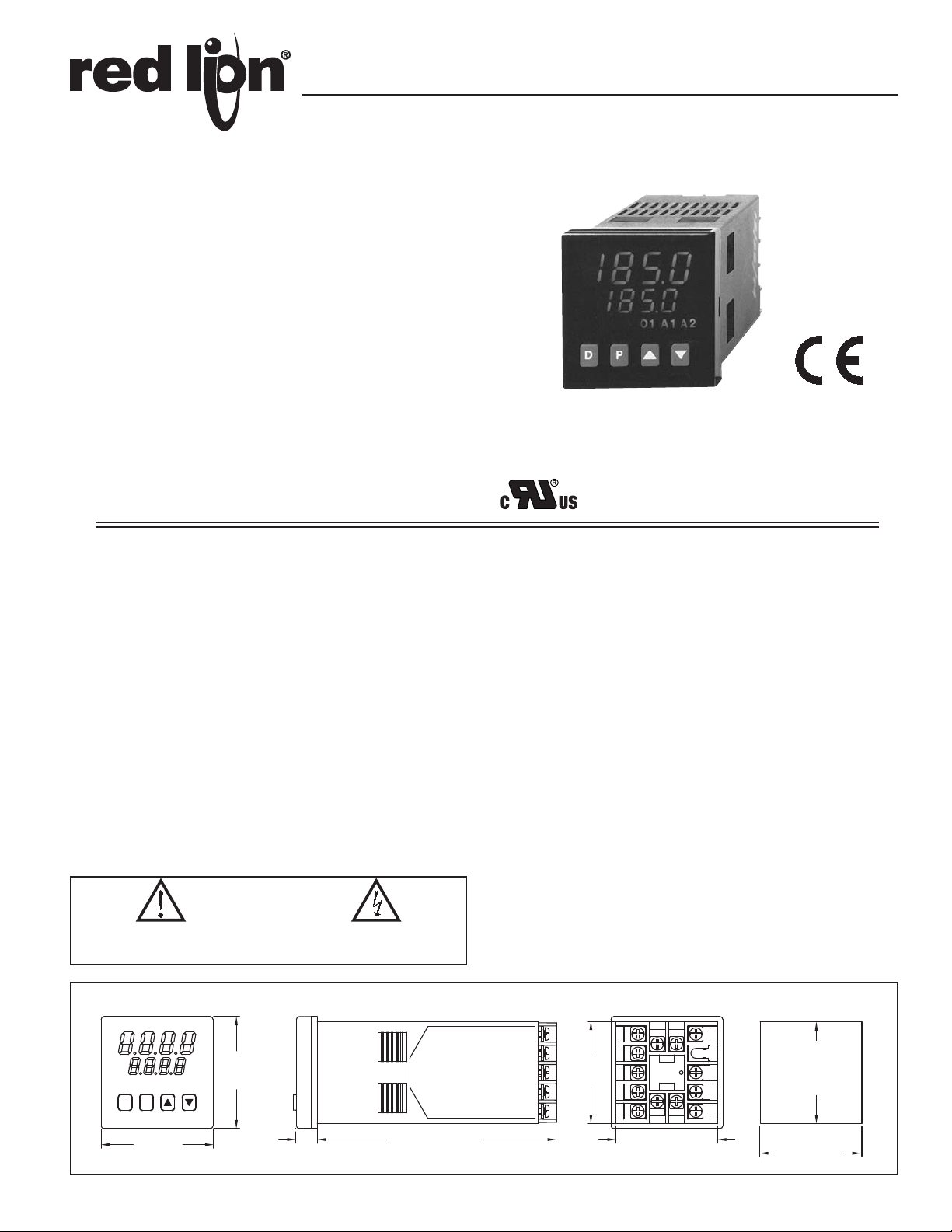
DIMENSIONS In inches (mm)
1.95
(49.5)
A2A1O1MNDV%P
D P
1.95
(49.5)
0.37
(9.4)
4.17 (105.9)
adjustable hysteresis. A standby feature suppresses the alarm during power-up
until the process stabilizes outside the alarm region. The second alarm can be
configured as a secondary PID output (heat/cool applications).
Optional Main Linear DC output (10 V or 20 mA) can be used for control or
process re-transmission purposes. Programmable output update time reduces
valve or actuator activity. The output range can be scaled independent of the
input range.
Optional Second Linear DC output (10 V or 20 mA) provides an independent
process re-transmission, while the main Linear DC output is being used for
control. The output range can be scaled independent of the input range.
Optional Remote Setpoint input (0/4 to 20 mA) allows for cascade control
loops; and allows for remotely driven setpoint signal from computers or other
similar equipment. Straightforward end point scaling with independent filtering
and local/remote transfer option expand the controller’s flexibility.
The optional RS485 serial communication interface provides two-way
communication between a P48 and other compatible equipment such as a printer,
PLC, HMI, or a host computer. In multipoint applications (up to thirty-two), the
address number of each P48 on the line can be programmed separately from 0 to
99. Data from the P48 can be interrogated or changed, and alarm output(s) may
be reset by sending the proper command code via serial communications. PC
software, SFCRM, allows for easy configuration of controller parameters. These
settings can be saved to disk for later use or used for multi-controller down
loading. On-line help is provided within the software.
The unit is constructed of a lightweight, high impact plastic case with a tinted
front panel. The front panel meets NEMA 4X/IP65 specifications when properly
installed. Multiple units can be stacked horizontally or vertically. Modern surfacemount technology, extensive testing, plus high immunity to noise interference
makes the controller extremely reliable in industrial environments.
PANEL CUT-OUT
1.76
(44.7)
1
2
3
4
5
1.76 (44.7)
13 14
6
7
8
9
10
1211
1.772
(45 )
1.772
(45 )
+0.024
-0.000
+0.6
-0.0
+0.024
-0.000
+0.6
-0.0
1
Page 2

SAFETY SUMMARY
All safety related regulations, local codes and instructions that appear in the
manual or on equipment must be observed to ensure personal safety and to
prevent damage to either the instrument or equipment connected to it. If
equipment is used in a manner not specified by the manufacturer, the protection
provided by the equipment may be impaired.
Do not use the P48 to directly command motors, valves, or other actuators not
equipped with safeguards. To do so can be potentially harmful to persons or
equipment in the event of a fault to the controller. An independent and redundant
process limit indicator with alarm outputs is strongly recommended.
SPECIFICATIONS
1. DISPLAY: Dual 4-digit
Upper Process Display: 0.4" (10.2 mm) high red LED
Lower Auxiliary Display: 0.3" (7.6 mm) high green LED
Display Messages:
“OLOL” - Appears when measurement exceeds + input range.
“ULUL” - Appears when measurement exceeds - input range.
“SENS” - Appears when measurement exceeds controller limits.
“...” - Appears when display values exceed + display range.
“-..” - Appears when display values exceed - display range.
LED Status Annunciators:
%P - Lower auxiliary display shows power output in (%).
MN - Flashing: Controller is in manual mode.
On: Local Setpoint (Remote Setpoint option)
Off: Remote Setpoint
DV - Lower auxiliary display shows deviation (error) from
setpoint.
O1 - Main control output is active.
A1 - Alarm #1 is active (for A1 option).
A2 - Alarm #2 is active OR
- Secondary output (02) is active.
2. POWER:
AC Versions: 85 VAC min. to 250 VAC max., 50 to 60 Hz, 8 VA max.
DC Versions:
DC Power: 18 to 36 VDC; 7 W
AC Power: 24 VAC 10%; 50 to 60 Hz, 9 VA
3. CONTROLS: Four front panel push buttons for modification and setup of
controller functions and one external user input for parameter lockout or other
functions.
4. MEMORY: Nonvolatile E
and values.
5. RANGE AND ACCURACY:
INPUT
RANGE
10 VDC
(-1 to 11)
20 mA DC
(-2 to 22)
ACCURACY *
(18 to 28°C)
0.10% of
reading
+0.02 V
0.10% of
reading
+0.03 mA
* Accuracies are expressed as percentages after 20 minutes warm-up. The
controller’s accuracy is specified in two ways: accuracy over an 18 to 28°C
range at 10 to 75% RH environment; and accuracy over a 0 to 50°C range
at 0 to 85% RH (non-condensing) environment. Accuracy over the wide
sensor range reflects the coefficient of the internal circuitry.
6. MAIN SIGNAL INPUT:
Sample Period: 100 msec
Response Time: Less than 300 msec typ., 400 msec max. (to within 99% of
final value w/step input; typically, response is limited to response time of
sensor)
Normal Mode Rejection: 40 dB @ 50/60 Hz (improves with increased
digital filtering.)
Common Mode Rejection: Greater than 120 dB, DC to 60 Hz
Protection: Input overload 120 VAC max. for 15 sec. max.
7. USER INPUT: Internally pulled up to +5 VDC (1 M).
V
= 5.25 VDC; V
IN MAX
I
= 1μA max.
OFF
Response Time: 120 msec max.
Functions:
Program Lock Integral Action Lock
Auto/Manual Mode Select Setpoint Ramp Enable
Reset Alarms Setpoint 1/Setpoint 2 Select
Local/Remote Setpoint Select Serial block print
8. CONTROL AND ALARM OUTPUTS:
Relay outputs with Form A contacts:
Contact Rating: 3 A @ 250 VAC or 30 VDC (resistive load)
1/10 HP @ 120 VAC (inductive load)
Life Expectancy: 100,000 cycles at max. load rating.
(Decreasing load and/or increasing cycle time, increases life
expectancy.)
2
PROM retains all programmable parameters
ACCURACY *
(0 to 50°C)
0.30% of
reading
+0.03 V
0.30% of
reading
+0.04 mA
= 0.85 V max.; V
IL
IMPEDANCE RESOLUTION
1 M ohm 300 V 10 mV
10 ohm 100 mA 10 μA
IH
MAX
CONTINUOUS
OVERLOAD
= 3.65 V min.;
9. MAIN CONTROL:
Control: PID or ON/OFF
Output: Time proportioning or Linear DC
Cycle time: Programmable
Auto-tune: When selected, sets proportional band, integral time, and
derivative time values.
10. ALARMS: 1 or 2 alarms (optional)
Modes:
Absolute high acting Absolute low acting
Deviation high acting Deviation low acting
Inside band acting Outside band acting
Reset Action: Programmable; automatic or latched
Standby Mode: Programmable; enable or disable
Hysteresis: Programmable
Annunciator: LED backlight for “A1”, “A2”
11. SECONDARY OUTPUT: Software selectable (overrides alarm 2)
Control: PID or ON/OFF
Output: Time Proportioning
Cycle time: Programmable
Proportional Gain Adjust: Programmable
Deadband /Overlap: Programmable
12. MAIN AND SECOND LINEAR DC OUTPUT: (optional)
Main: Control or re-transmission, programmable update rate from 0.1 sec to
250 sec
Second: Re-transmission only, fixed update rate of 0.1 sec
OUTPUT **
RANGE
0 to 10 V
0 to 20 mA
4 to 20 mA
ACCURACY *
(18 to 28°C)
0.10% of FS
+ 1/2 LSD
0.10% of FS
+ 1/2 LSD
0.10% of FS
+ 1/2 LSD
ACCURACY *
(0 to 50°C)
0.30% of FS
+ 1/2 LSD
0.30% of FS
+ 1/2 LSD
0.30% of FS
+ 1/2 LSD
COMPLIANCE RESOLUTION
10k ohm min. 1/3500
500 ohm max. 1/3500
500 ohm max. 1/2800
* Accuracies are expressed as percentages after 20 minutes warm-up. Output
accuracy is specified in two ways: Accuracy over an 18 to 28°C range at 10
to 75% RH environment; and accuracy over a 0 to 50°C range at 0 to 85%
RH (non-condensing) environment. Accuracy over the wide sensor range
reflects the coeffecient of the internal circuitry.
** Outputs are independently jumper selectable for either 10 V or 20 mA. The
output range may be field calibrated to yield approximately 10% overrange
and a small underrange (negative) signal.
13. REMOTE SETPOINT INPUT: (optional)
Input type: 0/4 to 20 mA
Input Resistance: 10
Overrange: -5% to 105%
Overload: 100 mA (continuous)
Scale Range: -999 to 9999
Resolution: 1 part in 10,000.
Accuracy:
At 25
° C: (0.1 % of full scale +½ LSD)
Over 0 to 50
°C range: (0.2% of full scale +½ LSD)
Reading Rate: 10/sec.
Setpoint Filtering: Programmable Digital
Setpoint Ramping: Programmable, 1 to 9999 units/minute.
14. SERIAL COMMUNICATIONS: (optional)
Type: RS485 multipoint, balanced interface
Baud Rate: 300 to 9600
Data Format: 7O1, 7E1, 7N2, 8N1
Node Address: 0 to 99, max of 32 units per line
Transmit Delay: 2 to 100 msec or 100 to 200 msec
Data Encoding: ASCII
Isolation w.r.t Main Input Common: 500 Vrms for 1 min. (50 V working)
Not isolated w.r.t. Remote Setpoint or Analog Output common
Note: RS485 and the Analog Output commons are not internally isolated
within the controller. The terminating equipment of these outputs must not
share the same common (ie. earth ground).
15. ENVIRONMENTAL CONDITIONS:
Operating Range: 0 to 50°C
Storage Range: -40 to 80°C
Operating and Storage Humidity:
85% max. relative humidity (non-condensing) from 0°C to 50°C.
Vibration According to IEC 68-2-6: Operational 5 to 150 Hz, in X, Y, Z
direction for 1.5 hours, 2 g.
Shock According to IEC 68-2-27: Operational 20 g (10 g relay), 11 msec
in 3 directions.
Altitude: Up to 2000 meters
2
Page 3

16. ISOLATION BREAKDOWN RATINGS:
AC line with respect to all Inputs and outputs: 250 V working (2300 V for
1 minute).
Main input with respect to Analog Outputs and Remote Setpoint Input:
50 V working (2300 V for 1 minute).
All other inputs and outputs with respect to relay contacts: 2000 VAC
Not isolated between Analog Output and Remote Setpoint commons.
17. CERTIFICA TIONS AND COMPLIANCES:
SAFETY
UL Recognized Component, File #E156876, UL873, CSA 22.2 No. 24
Recognized to U.S. and Canadian requirements under the Component
Recognition Program of Underwriters Laboratories, Inc.
Type 4X Enclosure rating (Face only), UL50
IEC 61010-1, EN 61010-1: Safety requirements for electrical equipment
for measurement, control, and laboratory use, Part 1.
IP65 Enclosure rating (Face only), IEC 529
ELECTROMAGNETIC COMPATIBILITY
Immunity to EN 50082-2
Level 2; 4 Kv contact EN 61000-4-2Electrostatic discharge
Level 3; 8 Kv air
EN 61000-4-3Electromagnetic RF fields
EN 61000-4-6RF conducted interference
EN 61000-4-8Power frequency magnetic fields
Emissions to EN 50081-2
Notes:
1. No loss of performance during EMI disturbance at 10 V/m.
Unit is panel mounted in a metal enclosure (Buckeye SM7013-0 or
equivalent) that provides at least 20 dB shielding effectiveness. Metal
panel is connected to earth ground.
Power Line and I/O cables routed in metal conduit connected to earth
ground.
2. Self-recoverable loss of performance during EMI disturbance at 10 Vrms:
Analog output may deviate during EMI disturbance.
For operation without loss of performance:
Install power line filter, RLC#LFIL0000 or equivalent.
OR
Install 2 ferrite cores, RLC#FCOR0000 or equivalent, to AC lines at
unit for frequencies above 5 MHz.
I/O cables routed in metal conduit connected to earth ground.
Refer to the EMC Installation Guidelines section of the manual for additional
information.
18. CONNECTION: Wire clamping screw terminals
19. CONSTRUCTION: Black plastic alloy case and collar style panel latch.
Panel latch can be installed for vertical or horizontal instrument stacking.
One piece tinted plastic bezel. Bezel assembly with circuit boards can be
removed from the case to change the output board without removing the case
from the panel or disconnecting wiring. Unit meets NEMA 4X/IP65
requirements for indoor use, when properly installed. Installation Category
II, Pollution Degree 2.
20. WEIGHT: 0.38 lbs (0.17 kgs)
Level 3; 10 V/m
80 MHz - 1 GHz
Level 4; 2 Kv I/OEN 61000-4-4Fast transients (burst)
Level 3; 2 Kv power
Level 3; 10 V/rms
150 KHz - 80 MHz
Level 4; 30 A/m
Level 3; 10 V/mENV 50204Simulation of cordless telephones
900 MHz ± 5 MHz
200 Hz, 50% duty cycle
Enclosure class AEN 55011RF interference
Power mains class A
1
2
FRONT PANEL FEATURES
In the normal operating mode, the unit displays the process value in the upper
display. One of the following parameters can be viewed in the lower display:
- Setpoint
- % Power Output
- Process Deviation
- Blank Display
The user scrolls through these parameters by pressing the D button. If
enabled, the control setpoint or power output (manual mode only) can be
directly modified in this mode.
In the normal operating mode, parameters are selected by use of the P button
and modified by use of the UP and DOWN buttons. Parameters are then entered
by the P button, which advances the user to the next parameter. Pressing the D
button immediately returns the controller to the normal operating mode without
changing the currently selected parameter.
HARDWARE FEATURES
A fast 100 msec input sampling rate provides quick controller response to a
process disturbance, thus providing excellent process control. Measurement
accuracy of 0.1% or better, provides close process control conforming to the
desired control setpoint value.
Low-drift, highly stable circuitry ensures years of reliable and accurate
process control. The recommended two year re-calibration interval is easily
accomplished via the programming menu.
REMOTE SETPOINT INPUT
The remote setpoint input facilitates the use of a remote signal to drive the
controller’s setpoint. The remote signal can be scaled independent to that of the
controller’s range. The controller’s response to local/remote setpoint transfers
can be programmed. Also, the remote signal is filtered by use of an adaptive
filter. With this filter, relatively large filtering time constants can be used
without suffering from long settling times. The time constant and filter disable
band are programmable. Additionally, the remote signal can also be velocity
limited (or ramped) to slow the controller’s response to changes in setpoint. This
results in a steady control response with no overshoot.
LINEAR DC ANALOG OUTPUTS
The Main Linear DC output has independent scaling, programmable output
update time and filter (damping) time. These parameters permit flexibility in
process configuration. The output can be set for 0 to 10 V, 0 to 20 mA or 4 to
20 mA ranges and can be configured for control or for re-transmission of input
or setpoint values.
A Second Linear DC output is dedicated for the re-transmission of the
process input signal. The output can be scaled and converted independent of the
input signal and Main Linear DC output. This output is isolated from the input.
SETPOINT FEATURES
The controller setpoint can be protected from out of range values by
programming the setpoint range limit values. Additionally, safeguards from
inadvertent data entry can be programmed.
A second setpoint can be selected by the user input and/or through the front
panel.
The setpoint ramp feature can be used to control the setpoint value at start-up
or any time a setpoint change is made, at a user programmable rate. This feature
reduces shock to the process and helps to minimize overshoot.
INPUT FEATURES
A programmable input filter can be used to stabilize readings from a process
with varying or oscillating process characteristics, helping to provide better
control.
The programmable user input can be used to control a variety of functions,
such as auto/manual transfer of the controller, reset alarm output(s), etc.
BASIC OPERATION
The P48 controls a process by receiving a linear DC signal representing the
process value, then calculating a control output power value by use of a
modified PID control algorithm. The unit controls the system with the new
output power value to keep the process at setpoint. The PID control algorithm
incorporates features which provide for high control accuracy and low
overshoot from process disturbances.
OUTPUT FEATURES
Programmable output power limits provide protection for processes where
excessive power can cause damage. Programmable output cycle time, output
hysteresis, and dampening can reduce output activity without degrading control
accuracy. The main outputs can operate in PID, ON/OFF, or manual control
modes.
CONTROL AND ALARM OUTPUTS
In addition to the Linear DC output, there are up to three relay outputs
available. Relay outputs can switch user applied AC or DC voltages for control
or alarm purposes.
3
Page 4

AUTO-TUNE
The P48 has an auto-tune feature which, on demand, automatically
determines the PID control parameters for a particular process. After completion
of auto-tune, the PID parameters are automatically optimized for that process
and loaded into non-volatile memory. The operator may view and modify the
parameters as desired.
Auto-tune may be invoked either at start-up or at setpoint, depending on the
process requirements. An auto-tune programmable dampening factor produces
various levels of process control and response characteristics.
RS485 SERIAL COMMUNICATIONS
The RS485 communications option allows the connection of up to 32 devices
on a single pair of wires with a distance of up to 4,000 feet and a maximum baud
rate of 9600. Since the same pair of wires are used for both transmit and receive,
only one way communication is possible at any given time. The controller has
a programmable response time to allow the host device adequate time to release
the communication line for a transmission.
Selected parameters from the P48 can be interrogated or changed, and alarm
output(s) may be reset by sending the proper command code via serial
communications. It is also possible to invoke Auto-tune through the serial port.
Serial communications used with SFCRM software allows for easy controller
parameter configuration by computer.
DUAL TIME PROPORTIONAL SYSTEMS
The P48 is available with dual time proportional outputs. The dual outputs
can be used for level or heat/cool applications. The A2 output can be configured
for Secondary (cool) control. This allows for dual PID control or ON/OFF
control with unbalanced hysteresis.
CONTROLLER PROGRAMMING
Front Panel Program Disable allows all of the controller’s set-ups to be
locked-out from further operator intervention after the initial set-up.
The following four programming modes allow the controller to adapt to any
required user-interface level:
UNPROTECTED PARAMETER MODE
mode when program disable is inactive or when the proper access code number
from the Protected Parameter Mode is entered. The Configuration Parameter
Modes can be accessed only from this mode.
“SP” - Enter setpoint
“OP” - Enter output power
“ProP” - Enter proportional band
“Intt” - Enter integral time
“dErt” - Enter derivative time
“AL-1” - Enter value for alarm #1
“AL-2” - Enter value for alarm #2
“CNFP” - Select configuration access point
“End” - Return to normal display mode
PROTECTED PARAMETERS MODE
This mode prevents access to the configuration modes without the proper access
code number. Only the parameters that are enabled in the Configuration 3
parameter (lock-out section) can be accessed.
“Intt” - Enter integral time
“dErt” - Enter derivative time
“AL-1” - Enter value for alarm #1
“AL-2” - Enter value for alarm #2
“CodE” - Enter value to access unprotected parameters and
configuration parameters
HIDDEN FUNCTION MODE
The functions in this mode may be locked-out individually in Configuration 3
parameter (lock-out section).
“SPSL” - Select local (SP1 or SP2) or remote setpoint
“trnF” - Transfer between automatic (PID) control and manual control
“tUNE” - Invoke/cancel PID Auto-tune
“ALrS” - Reset latched alarms
Unprotected Parameter Mode
Protected Parameter Mode
Hidden Function Mode
Configuration Parameter Mode
*
The Unprotected Parameter Mode is accessible from the Normal Display
*
The Protected Parameters Mode is enabled when program disable is active.
“ProP” - Enter proportional band
*
The Hidden Function Mode is accessible from the Normal Display Mode.
CONFIGURATION PARAMETER MODE
The Configuration Parameter Mode allows the operator to set-up the basic
requirements of the controller. It is divided into sections which group together
related programming steps, such as inputs, outputs, alarms, etc. Upon completion
of each section, the program returns to the Configuration Access Point allowing
the user to return to the Normal Display Mode.
Configuration 1, Inputs (1-IN)
“tYPE” - Select input signal type
“dCPt” - Select scaled display decimal point position
“rnd” - Enter rounding increment and trailing zeros for scaled display
“FLtr” - Select level of input filtering
“dSP1”
“InP1”
“dSP2”
“InP2”
“SPLO” - Enter setpoint lower limit
“SPHI” - Enter setpoint higher limit
“SPrP” - Enter setpoint ramp rate
“InPt” - Select user input function
Configuration 2, Outputs (2-OP)
“CYCt” - Enter time proportioning cycle time
“OPAC” - Select output control action
“OPLO” - Enter output power low limit
“OPHI” - Enter output power high limit
“OPdP” - Enter output control dampening
“CHYS” - Enter ON/OFF control hysteresis
“tcOd” - Select auto-tuning dampening
“ANtP” - Main Linear DC analog output range
“ANAS” - Main Linear DC analog output source
“ANut” - Main Linear DC analog output update time
“ANLO” - Main Linear DC analog output scaling low
“ANHI” - Main Linear DC analog output scaling high
Configuration 3, Parameter Lock-Outs (3-LC)
“SP” - Select setpoint access level
“OP” - Select power access level
“dEv” - Enable deviation display
“bdSP” - Enable blank display
“CodE” - Enter parameter access code
“PId” - Select PID access level
“AL” - Select alarm access level
“ALrS” - Enable alarm reset access
“SPSL” - Enable local/remote selection
“trnF” - Enable auto/manual mode selection
“tUNE” - Enable auto-tune invocation
Configuration 4, Alarms (4-AL)
“ACt1” - Select operation mode of alarm #1, or select main output
“rSt1” - Select reset mode of alarm #1
“Stb1” - Enable activation delay of alarm #1
“AL-1” - Enter value for alarm #1
“ACt2” - Select operation mode of alarm #2, or select second output
“rSt2” - Select reset mode of alarm #2
“Stb2” - Enable activation delay of alarm #2
“AL-2” - Enter value for alarm #2
“AHYS” - Enter hysteresis value for both alarms
Configuration 5, Second Output (5-O2)
“CYC2” - Enter time proportioning cycle time
“GAN2” - Enter relative gain
“db-2” - Enter deadband or overlap
Configuration 6, Serial Communications (6-SC)
“bAUd” - Select baud rate
“ConF” - Select character frame format
“Addr” - Enter address
“Abrv” - Select abbreviated or full transmission
“PoPt” - Select print options
Configuration 7, Remote Setpoint Input (7-N2)
“dSP1” - Enter remote setpoint display scaling value #1
“INP1” - Enter remote setpoint process scaling value #1
“dSP2” - Enter remote setpoint display scaling value #2
“INP2” - Enter remote setpoint process scaling value #2
“FLtr” - Enter remote setpoint filter time constant
“bAnd” - Enter remote setpoint filter disable band
“trnF” - Select Local/Remote setpoint transfer response
Configuration 8, Second Linear DC Analog Output (8-A2)
“A2tP” - Second linear DC analog range
“A2LO” - Second linear DC analog scaling low
“A2HI” - Second linear DC analog scaling high
- Scale main input
*
*
*
*
*
*
*
Configuration 9, Factory Service Operations (9-FS)
“Code 48” - Calibrate Instrument
“Code 66” - Reset parameters to factory setting
These parameters may not appear due to option configuration or other
*
programming.
4
Page 5
MULTIPLE UNIT STACKING
The P48 is designed for close spacing of multiple units. Units can be
stacked either horizontally or vertically. For vertical stacking, install the panel
latch with the screws to the sides of the unit. For horizontal stacking, the panel
latch screws should be at the top and bottom of the unit. The minimum
spacing from center line to center line of units is 1.96" (49.8 mm). This
spacing is the same for vertical or horizontal stacking.
Note: When stacking units, provide adequate panel ventilation to ensure that
the maximum operating temperature range is not exceeded.
1.96 (49.8)
MAX.
13 14
1
2
3
4
5
6
7
2.39 (60.7)
8
MAX.
9
10
1211
1
2
3
4
5
2.39 (60.7)
MAX.
13 14
1211
6
7
1.96 (49.8)
8
9
10
MAX.
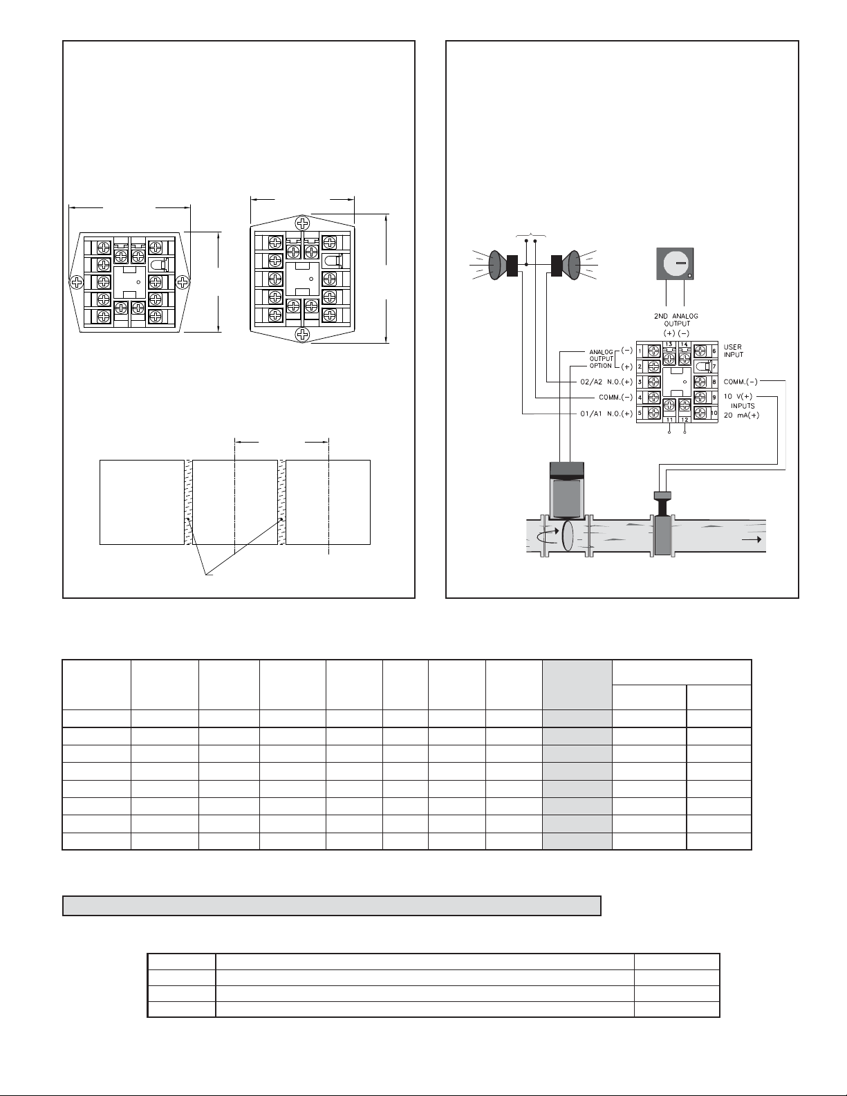
APPLICATION
WATER PROCESSING APPLICATION
A city water company needs to maintain a steady flow of water for their
customer needs. They have an existing 0 to 10 VDC flow transmitter to
measure the water flow. They need to control the water flow, have a high and
low alarm, and keep a recorded chart of the flow for later reference. The Main
Linear DC output of the P48 can be used to control the position of water
output values per the desired flow setpoint value. The P48 relay outputs can
be programmed to give a high flow alarm and a low flow alarm. With the
Second Linear DC output model, the flow measurement to the P48 can be
converted from 0-10 V to 4-20 mA and retransmitted to a 4-20 mA chart
recorder.
ALARM
POWER
+
-
CHART
RECORDER
HIGH
ALARM
LOW
ALARM
PANEL LATCH INSTALLED FOR
VERTICAL UNIT STACKING
PANEL LATCH INSTALLED FOR
HORIZONTAL UNIT STACKING
PANEL CUT-OUT SPACING FOR MULTIPLE UNIT STACKING.
HORIZONTAL ARRANGEMENT SHOWN.
STANDARD
PAN EL
1.96 (49.8)
MIN.
CONTROL
VALV E
UNIT POWER
FLOW
SENSOR
CUT-OUT
WATER FLOW
IF NEMA 4 IS NOT REQUIRED,
THIS PANEL MATERIAL MAY BE REMOVED.
(Terminal assignments are model number dependent.)
ORDERING INFORMATION
Options and Output Boards are factory configured per the part number specified. Part numbers without replacement output boards listed must be returned
to the factory for output board replacement.
DEDICATED
MAIN CONTROL
O1 OUTPUT
MAIN CONTROL
O1 or
A1(ALARM 1)*
DEDICATED
ALARM 1
A1 OUTPUT
A2 (ALARM 2)
OR O2
(SECONDARY)*
REMOTE
SETPOINT
INPUT @
RS485 @
MAIN
ANALOG
OUTPUT** @
SECOND
ANALOG
OUTPUT** @
REPLACEMENT
YES P4800001P4800011NA
Relay P4810000P4810010RBD48100
Relay Relay YES P4810101P4810111NA
Relay Relay YES YES P4810105P4810115NA
Relay Relay YES YES P4810107P4810117NA
Relay Relay YES YES P481010AP481011ANA
Relay Relay Relay P4811100P4 811110RBD48111
Relay Relay Relay YES P4811102P4 811112RBD48111
* This output is programmable as either Control (PID) or as an Alarm.
** These part numbers are jumper and program selectable for either a current or a voltage Linear DC output.
@ These part numbers are equipped with a second setpoint.
OUTPUT
BOARD
PART NUMBERS
85 to 250 VAC18-36 VDC/24 VAC
Option Boards are installed at the factory for the appropriate models. These boards are only needed for field replacement.
ACCESSORIES
MODEL NO. DESCRIPTION PART NUMBERS
SFCRM
ICM4
ICM5
*Crimson Software is available for download from http://www.redlion.net
Crimson 2 PC Configuration Softwware for Windows 98, ME, 2000 and XP (for RS485 models)
RS232/RS485 Serial Converter Module
Three Way Isolated RS232/RS485 Serial Converter Module
5
SFCRM
ICM40030
ICM50000
Page 6

This page intentionally left blank
6
Page 7

This page intentionally left blank
7
Page 8

The Company warrants the products it manufactures against defects in materials and workmanship
LIMITED WARRANTY
for a period limited to two years from the date of shipment, provided the products have been stored,
handled, installed, and used under proper conditions. The Company’s liability under this limited
warranty shall extend only to the repair or replacement of a defective product, at The Company’s
option. The Company disclaims all liability for any affirmation, promise or representation with
respect to the products.
The customer agrees to hold Red Lion Controls harmless from, defend, and indemnify RLC against
damages, claims, and expenses arising out of subsequent sales of RLC products or products
containing components manufactured by RLC and based upon personal injuries, deaths, property
damage, lost profits, and other matters which Buyer, its employees, or sub-contractors are or may be
to any extent liable, including without limitation penalties imposed by the Consumer Product Safety
Act (P.L. 92-573) and liability imposed upon any person pursuant to the Magnuson-Moss Warranty
Act (P.L. 93-637), as now in effect or as amended hereafter.
No warranties expressed or implied are created with respect to The Company’s products except those
expressly contained herein. The Customer acknowledges the disclaimers and limitations contained
herein and relies on no other warranties or affirmations.
Red Lion Controls
Headquarters
20 Willow Springs Circle
York PA 17406
Tel +1 (717) 767-6511
Fax +1 (717) 764-0839
Red Lion Controls
Europe
Printerweg 10
NL - 3821 AD Amersfoort
Tel +31 (0) 334 723 225
Fax +31 (0) 334 893 793
Red Lion Controls
India
54, Vishvas Tenement
GST Road, New Ranip,
Ahmedabad-382480 Gujarat, India
Tel +91 987 954 0503
Fax +91 79 275 31 350
8
Red Lion Controls
China
Unit 101, XinAn Plaza
Building 13, No.99 Tianzhou Road
ShangHai, P.R. China 200223
Tel +86 21 6113-3688
Fax +86 21 6113-3683
 Loading...