

red lion LGS, LGB, LGM, LGD Technical Manual
ENT
RST
F2
ESC SEL
F1
2.95
E
SELECT PROPER VOLTAGE
BEFORE APPLYING POWER
CAUTION:
115 VAC 230 VAC
50/60 HZ, 10 VA
LB01269
2.64
2.68
2.68
.155 (3.8)
2.95 (74.9) 5.87 (149.1)
.15
(3.8)
(74.9)
(67.1)
(68 )
(68)
+.03
-.01
+.6
-.3
PRS
Tel +1 (717) 767-6511
Fax +1 (717) 764-0839
www.redlion.net
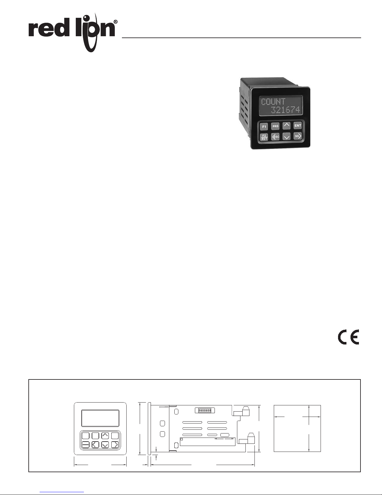
LEGEND SERIES
MODEL LGS -Single Preset Counter/Rate Indicator
MODEL LGD - Dual Preset Counter/Rate Indicator
MODEL LGB - Four Preset Batch/Counter/Rate Indicator
MODEL LGM - Six Preset Counter/Rate Indicator
DESCRIPTION
The Legend Series consist of four different models that are multi-function
count and rate indicators. There can be up to six presets and six programmable
outputs depending upon the unit. The count and rate displays have separate
programmable decimal point settings. The unit also has rate peak and valley
displays that show the highest and lowest rate readings since they were reset
(peak and valley readings are not retained when power is removed). There are
five Programmable User Inputs, three external remote inputs and two front
panel function keys, which allow the user to select from a variety of functions.
The two line by eight character alphanumeric display with English menus,
allows for easy viewing and simple programming of the units. The four scroll
through indication displays can be programmed to show other parameters and if
desired, automatically scroll at one of the two programmable rates. A program
disable DIP switch used with an external User Input can be utilized to protect
the settings and guarantee that no unwanted changes occur during operation.
The standard RS485 serial communication feature provides the capability of
two-way communication between the Legend unit and other compatible
equipment such as a printer, a programmable controller, or a host computer.
The Baud Rate is programmable and ranges from 1200 to 9600. The unit
address number can be programmed from 00-99. Up to thirty-two units can be
installed on a single pair of wires, each with an individual address. The Count
value(s), Preset(s), Rate, Peak, Valley, etc can all be interrogated or changed.
The output(s), counters(s), rate and peak readings can be reset, by sending the
proper command codes via serial communications or by activating a
programmable user input. When a user input, selected for the print request
function, is activated, the values specified in the Program Print Options module
can be transmitted to a printer.
Optional Programming Software (SFLGP) for IBM
available to program all of the Legend configuration parameters such as User
Inputs, count modes, etc. The software allows unit configurations to be created,
uploaded, downloaded, and saved to a file for rapid programming of the Legend.
The Legend offers a choice of seven programmable counting modes for use
in applications requiring Bi-directional, Anti-coincidence, and Quadrature
counting. A separate external inhibit terminal can be used in conjunction with
any of the count modes. The input circuitry is switch selectable to accept signals
from a variety of input sources. A unit may be programmed to register counts on
both edges of the input signal providing frequency doubling capability.
A Legend unit will indicate an overflow condition when the capacity of a
Count display (Process, Batch, or Total) is exceeded, by flashing the word
“OVERFLOW” in the appropriate display.
All count values and program setting are retained when unit power is
removed in nonvolatile memory.
®
compatible PCs is
Bulletin No. LEGEND-F
Drawing No. LP0324
Released 07/11
2X8 TRANSMISSIVE LCD, NEGATIVE IMAGE, WITH LED
BACKLIGHTING
FOUR USER PROGRAMMABLE INDICATION DISPLAYS
OPTIONAL PROGRAMMING SOFTWARE
ENGLISH PROGRAMMING MENUS
RATE, PEAK & VALLEY INDICATION
ABILITY TO LOCKOUT OPERATOR ACCESS TO PROGRAMMING
PARAMETERS
ACCEPTS COUNT RATES UP TO 23 KHz (for Model LGS)
BI-DIRECTIONAL COUNTING, UP/DOWN CONTROL
QUADRATURE SENSING (Up to 4 times resolution)
COUNT INHIBIT PIN AVAILABLE FOR ALL COUNT MODES
SEPARATE INPUT SCALING FOR RATE & COUNT
PROGRAMMABLE CONTROL INPUTS
INPUTS ARE SWITCH SELECTABLE FOR MAGNETIC PICKUPS
RELAY OUTPUT(S) (Field Replaceable)
OUTPUT(S) ASSIGNABLE TO COUNT OR RATE
SOLID STATE CURRENT SINKING OUTPUT(S)
115/230 VAC SWITCH SELECTABLE
RS485 SERIAL COMMUNICATIONS
NONVOLATILE MEMORY
NEMA 4X/IP65 SEALED FRONT PANEL BEZEL
DIMENSIONS In inches (mm)
Note: Recommended minimum clearance (behind the panel) for
mounting clip installation is 3.0" (76.2) H x 4.0" (101.6) W.
1
PANEL CUT-OUT
DESCRIPTION (Cont’d)
A Legend unit will indicate an overflow condition when the capacity of a
Count display (Process, Batch, or Total) is exceeded, by flashing the word
“OVERFLOW” in the appropriate display.
All count values and program setting are retained when unit power is
removed in nonvolatile memory.
The choice of several reset cycle modes along with the compatibility of count
and control inputs to other RLC products, provides added versatility for standalone and system counter needs.
The rate input uses the time interval method (1/tau) to calculate the rate
value. This method insures high resolution at all input rates. The unit counts
input pulses and after the programmable minimum update time elapses and the
next count edge occurs, the unit will take the number of edges that occurred
during the elapsed time to calculate the rate value. The minimum update time
can be as low as 0.1 second per update, enabling quick response to rate changes.
At slower rates, averaging can be accomplished by programming the Minimum
and Maximum Update Time for the desired response. Extensive scaling
capabilities allow practically any reading at very slow input rates.
The construction of the Legend series is a light weight high impact plastic
case with a clear viewing window. The sealed front panel with the silicone
rubber keypad meets NEMA 4X/IP65 specifications for wash-down and/or
dusty environments, when properly installed. Plug-in style terminal blocks
simplify installation and wiring change-outs.
SAFETY SUMMARY
All safety related regulations, local codes and instructions that appear in the
manual or on equipment must be observed to ensure personal safety and to
prevent damage to either the instrument or equipment connected to it. If
equipment is used in a manner not specified by the manufacturer, the protection
provided by the equipment may be impaired.
Do not use this unit to directly command motors, valves, or other actuators
not equipped with safeguards. To do so, can be potentially harmful to persons
or equipment in the event of a fault to the unit.
MODELS - LGS & LGD
The single preset unit has one NPN open collector output and the dual preset
unit has two outputs which are activated from presets 1 and 2 respectively. Each
output can be assigned to either Rate or Count display. An optional relay board
can be installed that operates in parallel with the solid state output(s).
MODEL - LGB
The process counter is used to monitor the progress of the count within the
batch. Presets 1 and 2 are assigned to the Process Counter and activate relay
outputs 1 and 2 respectively.
Presets 3 and 4 can be assigned to either the Batch Counter, Totalizer, or Rate
indicator. Presets 3 and 4 activate the NPN open collector outputs O3-SNK and
O4-SNK respectively.
MODEL - LGM
The Multi Preset unit has six Presets (1-6) which control NPN open collector
outputs 01-SNK to 06-SNK respectively. Preset one through four are assigned
to the count display. Presets 5 and 6 can be assigned to either the Rate or Count
display.
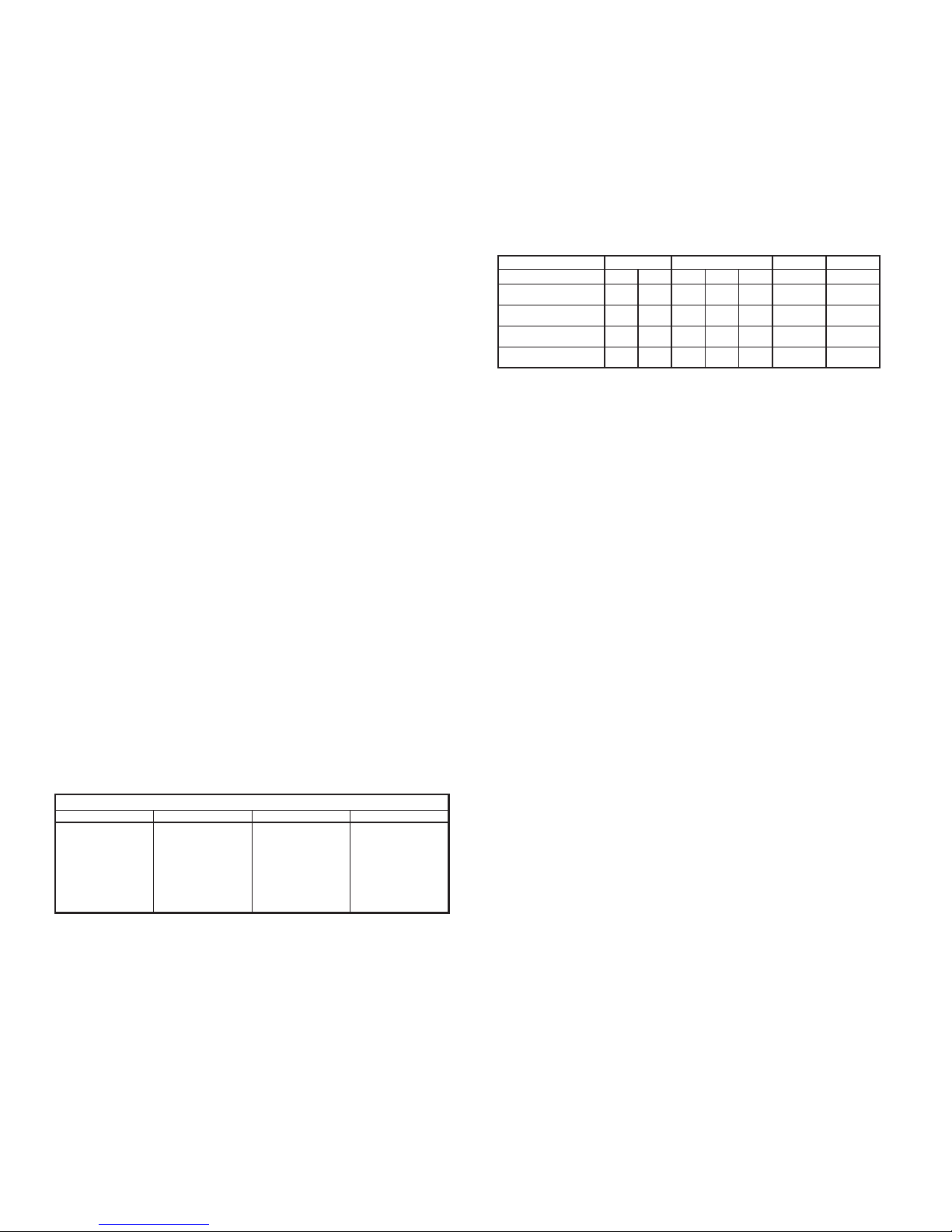
AVAILABLE INDICATION DISPLAYS AND PRESETS FOR EACH MODEL
LGS LGD LGB LGM
RATE
PEAK
VALLEY
COUNT
(1 Preset)
RATE
PEAK
VALLEY
COUNT
(2 Presets)
RATE
PEAK
VALLEY
PROCESS
BATCH
TOTAL
(4 Presets)
RATE
PEAK
VALLEY
COUNT
(6 Presets)
SPECIFICATIONS
1. DISPLAY: 2x8, 0.3" (7 mm) high characters, negative image transmissive
LCD, with yellow/green or red LED backlighting.
2. POWER:
AC Operation: 115/230 VAC ±10%, 50/60 Hz, 10 VA, switch selectable.
DC Operation: +12 VDC ±20% @ 250 mA.
3. MEMORY: Non-volatile memory retains all programming information.
Count and Preset values are written to non-volatile memory when power is
interrupted. All other programming parameters are written to memory when
programming mode is exited. If power is removed while in the programming
menus, the parameters are restored to previously saved settings.
Data Retention: 10 years minimum
4. SENSOR POWER: +12 VDC ±25% @ 100 mA.
5. INPUTS A and B: DIP Switch selectable to accept count pulses from a
variety of sources including switch contacts, outputs from CMOS or TTL
circuits, and all standard RLC sensors.
LOGIC: Input trigger levels V
= 1.5 V
IL
; VIH = 3.75 V
MAX
MIN
.
Current sinking: Internal 7.8 K pulled up internally to +12 VDC,
= 1.6 mA.
I
MAX
Current sourcing: Internal 3.9 K pull-down, 7.3 mA @ 28 VDC
Debounce: Damping capacitor provided for switch contact bounce.
Limits count speed to 50 Hz and input pulse widths to 10 msec min.
MAGNETIC PICKUP:
Sensitivity: 200 mV peak.
Hysteresis: 100 mV.
Input impedance: 3.9 K @ 60 Hz.
Maximum input voltage: ±50 Vp
Note: For magnetic pickup input, the sink/source DIP switch must be in
the SRC position.
6. RATE ACCURACY: ±0.01%
7. RATE MINIMUM INPUT FREQUENCY: 0.01 Hz.
8. MAXIMUM COUNT RATE IN KHz:
MODEL CNT + DIR QUAD ADD/ADD ADD/SUB
LGS (Single Preset) 23 11 9 7 5.5 23 12
LGD (Dual Preset) 20 10 8.5 7 5 20 10
LGB (Batch) 17 8774 17 9
LGM (Six Preset) 15 7773 15 8
X1 X2 X1 X2 X4 X1* X1*
Notes:
1. Maximum count rates given are for Process counter set for Auto reset with
the auto cycle preset set to an equivalent of 100 count pulses or greater.
With auto cycle presets less than 100 count pulses, with Count SF =
0.5000 and Count Scale Multiplier = X1, would be 50.
2. Maximum count rate given for X2 & X4 count modes are given for 50%
duty cycle signals and Quad signals with 90
o
phase shift.
*Inputs A & B count rates summed.
9. CONTROL INPUTS:
Programmable user inputs (3): Internal 10 K pull-up to +5 VDC,
VIL = 1.0 V
Inhibit: Internal 10 K pull-up to +5 VDC, V
10. SERIAL COMMUNICATIONS:
; VIH = 4.0 V
MAX
, response time = 10 msec.
MIN
= 1.0
IL
; VIH = 4.0 V
MAX
Type: RS-485 Multi-point Balanced Interface (2 Wire).
(Can connect up to 32 units on a single pair of wires)
Baud Rate: Programmable from 1200 to 9600.
Maximum Addresses: Programmable from 00 to 99.
(Actual number on a single pair of wires is limited by serial hardware
specifications)
Transmit Delay: Programmable for 0.002 or 0.100 second.
Data Format: 10 Bit Frame; 1 start bit, 7 data bits, 1 parity bit, and 1 stop
bit. Parity is programmable for either ODD, EVEN, or No Parity.
11. OUTPUT(S):
Solid-State: Current sinking NPN open collector transistor.
V
= 1V
CE
(Internal Zener Diode Protection).
@ 100 mA max. VOH = 30 VDC max.
SAT
Relay(s): Mounted on field-replaceable P.C. board. Form C contacts rated at
5 amps @ 120 VAC/240 VAC or 28 VDC (resistive load), 1/8 H.P. @ 120
VAC (inductive load). The operate time is 5 msec nominal and the release
time is 3 msec nominal.
Programmable Timed Output(s): Programmable time ranges from 0.01 to
99.99 seconds, ±0.05% - 11 msec max.
12. CERTIFICATIONS AND COMPLIANCES:
SAFETY
IEC 61010-1, EN 61010-1: Safety requirements for electrical equipment
for measurement, control, and laboratory use, Part 1.
IP65 Enclosure rating (Face only), IEC529
Type 4X Indoor Enclosure rating (Face only), UL50
ELECTROMAGNETIC COMPATIBILITY
Immunity to EN 50082-2
Electrostatic discharge EN 61000-4-2
Level 2; 4 Kv contact
Level 3; 8 Kv air
Electromagnetic RF fields EN 61000-4-3 Level 3; 10 V/m
Fast transients (burst) EN 61000-4-4 Level 4; 2 Kv I/O
80 MHz - 1 GHz
1
Level 3; 2 Kv power
RF conducted interference EN 61000-4-6 Level 3; 10 V/rms
150 KHz - 80 MHz
Power frequency magnetic fields EN 61000-4-8 Level 4; 30 A/m
Emissions to EN 50081-2
RF interference EN 55011 Enclosure class A
Power mains class A
Note:
1. When the unit is DC powered from terminal TBA pin 5 (common) and
terminal TBA pin 3 (DC OUT/IN) a power line filter was installed, RLC
MAX
1
MIN
.
.
2
SPECIFICATIONS (Cont’d)
ENT
RST
F2
ESC SEL
F1 F1
SELESC
F2
RST
ENT
F1
SELESC
F2
RST
ENT ENT
RST
F2
ESC SEL
F1
PRS
PRSPRS
PRS
4
3
2
1
MAIN DISPLAY LOOP
>
>
>>
>>>
>
PRS
S.F.'S
PROGRAM
ESC
<
ESC
<<
ESC
>
SEL
>
SEL
>>>
>>>
ENTENT
>
>
>
SEL
>
SEL
OPTIONS
PROGRAM
PRINT OP
PROGRAM
COM.PORT
PROGRAM
DISPLAY
PROGRAM
OUTPUTS
PROGRAM
USER
PROGRAM
COUNTER
PROGRAM
RATE
PROGRAM
SCALING
PROGRAM
816352
COUNT
PROGRAM
MODE
SCALE
FACTORS
VALLEY
9124
PEAK
29637
RATE
PROGRAM
PRESETS
AND
COUNTER
LOAD
VALUE
SEL
>
SEL
>
SEL
>
SEL
>
SEL
>
SEL
>
SEL
>
*
>
SEL
>
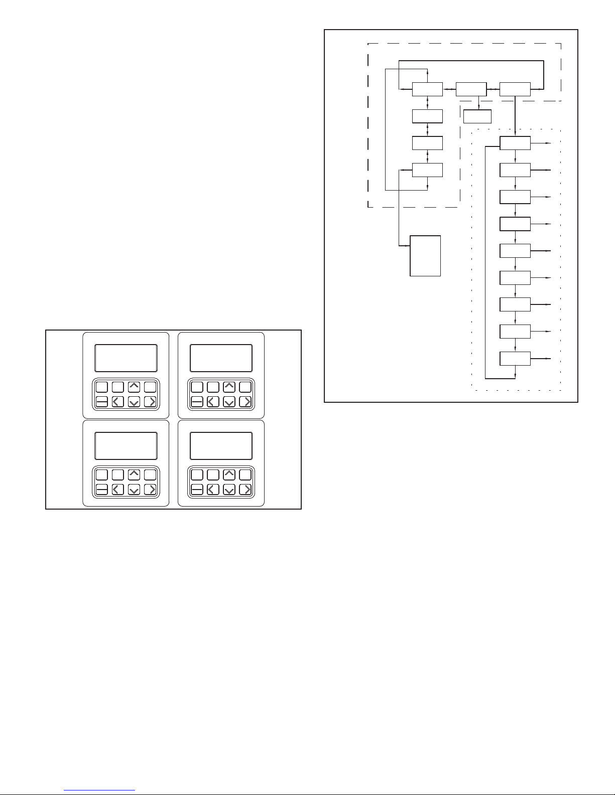
PROGRAMMING LOOP
... DOTTED LINE:
MAIN DISPLAY LOOP
--DASHED LINE:
1-4 - THE FOUR INDICATION DISPLAYS
PROGRAM DISABLE FUNCTION
* - CAN BE DISABLED USING THE
20406
*
#LFIL0000 or equivalent, so as not to impair the function of the unit.
Refer to the EMC Installation Guidelines section of the manual for additional
information.
13. ENVIRONMENTAL CONDITIONS:
Operating Temperature: 0 to 50°C
Storage Temperature: -40 to 70°C
Operating and Storage Humidity: 85% max. (non-condensing) from 0°C
to 50°C.
Vibration According to IEC 68-2-6: 5 to 150 Hz, in X, Y, Z direction for
1.5 hours, 2 g.
Shock According to IEC 68-2-27: Operational 20 g (10 g relay), 11 msec in
3 directions.
Altitude: Up to 2000 meters
14. CONSTRUCTION: High impact plastic case with clear viewing window.
The front panel meets NEMA 4X/IP65 requirements for indoor use when
installed properly. Installation Category II, Pollution Degree 2. Panel gasket
and mounting clips included.
15. WEIGHT: 1.5 lbs. (0.68 Kg)
PROGRAMMING
The Legend Series provides an easy to use, menu driven programming
interface. The English prompts, the front panel keypad, and the flashing display
aids the operator during programming. In the normal run mode, the main
display loop allows the user to scroll through the four programmable indication
displays, using the direction keys. From the main loop, presets and scale factors
can be accessed directly for changing parameters. All other parameters are
accessed through the programming loop. In the programming loop, parameters
can be viewed or changed and the operator can exit anywhere in the loop.
Shown to the side is part of the main display loop and part of the programming
loop of a Dual Preset Legend (LGD) unit. Also shown are four different views
of the indication displays.
PROGRAMMABLE FUNCTIONS
PRESET(S)
Ranges from -99999 to 999999
Counter Load ranges from -99999 to 999999
SCALE FACTORS (RATE & COUNT)
Range from 0.0001 to 5.9999
COUNT SCALE MULTIPLIER
Multiplies the contents of the 9-digit internal counter or the 11-digit internal
totalizer by a factor of 1, 0.1, 0.01 or 0.001 to view the desired number of
significant digits on the 6-digit Counter display or the 8-digit Totalizer display.
DECIMAL POINT
Separate decimal point location for Count and Rate displays.
RATE SCALE MULTIPLIERS
by a factor of 0.01, 0.1, 1, 10, 100, or 1000 to view the desired number of
significant digits on the 6-digit Rate display. The desired time units that the rate
is to be displayed, can also be programmed as per Second (x1), per Minute
(x60), or per Hour (x3600).
Multiplies the contents of the actual internal rate, pulses per second (PPS),
0.00
0.000
0.0000
0.00000
0
0.0
UPDATE TIME
The Rate Minimum/Maximum Update Times range from 0.1 to 99.9 seconds
which provides averaging capability for non-consistent pulse spacing.
COUNTING MODES
Count with Direction
Count with Direction (X2)
Quadrature
Quadrature (X2)
Quadrature (X4)
2-Input Anti-coincidence Add/Add
2-Input Anti-coincidence Add/Subtract
A separate Inhibit input, is available for all count modes.
RESET MODES
Manual Reset
Automatic Reset at Preset
Reset at Beginning Of Output 1
Reset at End Of Timed Output 1
Reset at Beginning Of Output 2
Reset at End Of Timed Output 2
Reset at Beginning Of Output 1 or Output 2
Reset at End Of Timed Output 1 or Output 2
MODEL LGB ONLY
Reset at Beginning Of Output 3
Reset at End Of Timed Output 3
Reset at Beginning Of Output 4
Reset at End Of Timed Output 4
Reset at Beginning Of Output 3 or Output 4
Reset at End Of Timed Output 3 or Output 4
3
 Loading...