

Page 1
THE LEGEND PLUS BATCH
MODEL LGPB INSTRUCTION MANUAL
Page 2

INTRODUCTION
The Legend Plus Batch unit (LGPB) is another unit in our multi-purpose series
of industrial control products that are field-programmable for solving various
applications. This series of products is built around the concept that the end user
has the capability to program different indication and control requirements.
The Legend Plus which you have purchased, has the same high quality
workmanship and advanced technological capabilities that have made Red Lion
Controls the leader in today’s industrial market.
Red Lion Controls has a complete line of industrial indication and control
equipment, and we look forward to servicing you now and in the future.
CAUTION: Risk of Danger.
Read complete instructions prior to
installation and operation of the unit.
CAUTION: Risk of electric shock.
Page 3

Table of Contents
GENERAL DESCRIPTION ·······················································5
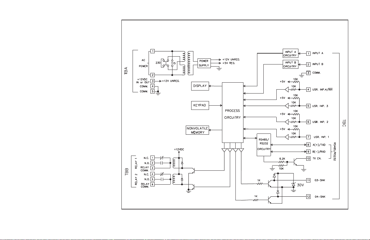
BlockDiagram ······························································ 5
SafetySummary ···························································· 6
BasicOperation ·····························································6
Messages ································································· 8
User Input Message Request Operation ········································8
Binary Message Request Operation ···········································8
Output Message Request ···················································8
MessageCancellation ······················································ 8
OverflowIndication ·························································· 9
Peak&Valley ······························································9
NormalOperatingMode ·······················································9
KeypadDescription ·························································10
KeypadFunctions ························································ 10
ProgramCodeNumber(PRO.CODE) ·········································11
Front Panel Accessible Functions With Program Disable ·····························11
PROGRAMMING GENERAL DESCRIPTION ·········································12
Program Presets & Counter Load Module ·········································13
PresetValues ··························································· 13
Counter Load Value ······················································13
Program Scale Factors Module ················································14
Count Scale Factor ·······················································14
RateScaleFactor ························································14
TotalScaleFactor ·······················································14
PROGRAMMING MENUS ······················································· 15
Program Scaling Module ····················································· 16
Count Scale Factor (COUNT SF) ············································16
RateScaleFactor(RATESF) ··············································· 16
TotalScaleFactor(TOTSF) ················································16
Count Scale Multiplier (CNT.SCM) ···········································16
RateScaleMultiplier(RATESCM) ···········································16
RateConversionFactor(RATEPER) ·········································16
DecimalPoint(CNT.DP,RATEDP,TOTDP) ···································17
Change Count Value With Scale Factor (CHG CNT W/SF) ·························17
-1-
Page 4

Program Rate Module ······················································· 18
Minimum And Maximum Update Time ·········································18
Program Counter Module ····················································· 19
Count Modes (CNT. INPUT) ················································19
ProcessResetAction(PRC.RST.) ··········································· 20
ProcessAutomaticReset(PAUTO.RS) ·······································20
BatchResetAction(BAT.RST) ·············································21
BatchAutomaticReset(BAUTO.RS) ········································· 21
TotalResetAction(TOT.RST.) ············································· 21
Program User Module ······················································· 22
Binary Message Request (BIN MSG REQ) ·····································22
NoMode······························································· 23
MaintainedReset(MNTRST) ··············································· 23
MomentaryReset(MOMRST) ··············································23
ResetOutput(RSTOUT) ··················································23
SetOutput(SETOUT) ····················································23
View/FreezeDisplay(VIEWDS1) ············································ 23
Change Display (CHG DSP) ················································ 24
Request Message (REQ MSG#) ·············································24
ClearMessage(CLRMSG)·················································24
SkipPreset(SKIPPRS) ··················································· 24
Counter Load (CNT LD) ··················································· 24
Print Request (PRINT RQ) ·················································24
ProgramDisable(PGM.DIS.) ··············································· 24
Inhibit Count ···························································· 24
Program Outputs Module ·····················································25
Phase ································································· 25
Output Modes - Timed, Latched or Boundary ···································25
Rate Output On/Off Delay ·················································· 25
Output End (Reset) Modes - OUT1 END, OUT2 END ·····························27
Output Power Up State (OFF@P.UP, SAVE@P.DN OR ON @P.UP) ··················27
Reset Output With Count (RST/C-EN OR DS) ···································27
Request Message (REQMSG#—) ············································27
Program Display Module ····················································· 28
Displays1to4 ·························································· 28
Scroll Speed (SCRO.SPD) ·················································28
-2-
Page 5

Display Intensity (DSP.LEVEL) ··············································28
CustomDisplayLines(CUST.DSP.1/CUST.DSP.2)······························28
Mnemonic ······························································ 28
Program Message Module ····················································30
MessageType ··························································30
MessageText ··························································· 31
MessagePriority(PRIOR-1) ···············································33
Blinking Message (BLNK-YES/NO) ···········································33
Multiplex (MUX - YES/NO) ·················································33
Maintained/Momentary Message Request ······································33
MessageCancellation ····················································· 33
MessageTime ··························································33
MessageColor ·························································· 33
ProgramCommunicationPort··················································34
BaudRate ····························································· 34
Parity/NumberOfDataBits ················································ 34
UnitAddress ····························································34
SerialTransmitDelay ····················································· 34
Program Print Options Module ················································· 35
Mnemonics(MNEM-Yes/No) ················································35
TransmitandReset(TX&R-Yes/No) ··········································35
Message0(MSG0-Yes/No) ················································ 35
Program Options Module ····················································· 36
OperatorAccess ························································· 36
PresetTracking ························································· 36
ProgramCode(PRO.CODE) ···············································36
UserSettings ··························································· 37
LGPB Factory Settings Program Sheet ········································37
LGPB User Settings Program Sheet ··········································39
SERIALCOMMUNICATIONS ····················································42
ProgrammingSoftware ······················································· 42
Installing Software ······················································· 42
UsingSoftware ·························································· 42
CommunicationFormat ······················································ 43
Sending Commands and Data ·················································43
ReceivingData ···························································· 46
-3-
Page 6

Serial Connections ·························································· 47
Connecting to a Host Terminal ··············································48
Troubleshooting Serial Communications ··········································49
INSTALLATION&CONNECTIONS ················································ 50
EMCComplianceInstallation ·················································· 51
Additional EMC Installation Guidelines ··········································· 51
Wiring Connections ·························································52
A.C.PowerWiring ·······················································52
DCPowerWiring ························································ 52
SerialCommunications ····················································52
User Input Wiring ··························································52
OutputWiring ····························································· 52
Signal Wiring ······························································ 53
Inputs A & B ····························································53
Installation&RemovalofRelayBoard ··········································· 54
DIPSwitchSet-up ··························································54
Various Sensor Output Connections ············································· 55
SPECIFICATIONS & DIMENSIONS ···············································57
TROUBLESHOOTINGGUIDE ···················································· 59
APPENDIX“A”-SCALINGFORCOUNTANDTOTALINDICATION ······················62
Scaling For Count Indication ··················································62
Count Scale Multiplier ······················································· 63
ScalingForTotalIndication ···················································64
APPENDIX“B” -SCALINGFORRATEINDICATION ··································65
RateScaleMultiplier ························································66
APPENDIX“C” -APPLICATION··················································68
APPENDIX“D” -ORDERINGINFORMATION ·······································71
APPENDIX“E” -FLOWCHARTFOLD-OUT······································ (Insert)
-4-
Page 7
GENERAL DESCRIPTION
The Legend Plus Batch Counter (LGPB) is a
multi-input, counting panel instrument that
features process, batch, and total counting, as well
as a timeinterval rate indicator. All four available
presets can be assigned to the process counter or
the rate indicator. Outputs three and four can also
be assigned to the batch or total indicator.
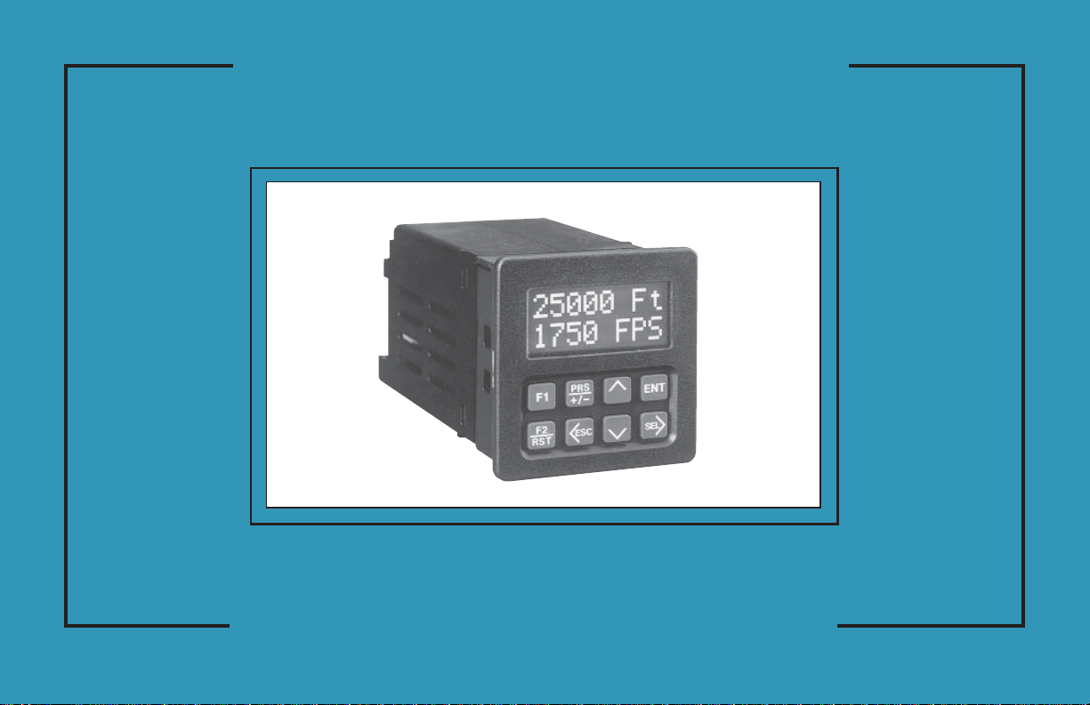
The Legend Plus has advanced features that
allow the unit to be more closely coupled to the
application. The unit features a 2 line by 8
character alphanumeric display, allowing the
value mnemonics and programming menus to be
easily read. The unit is available in single or dual
color display models. The four scroll-through
indication displays can be programmed to show
various parameters and to automatically scroll.
On dual color models, each indicationdisplay can
be programmed for either color. The mnemonics
corresponding to the maindisplay values (RATE,
PROCESS, BATCH, TOTAL), can be
individually programmed and modified as
desired. For example, the RATE mnemonic can
be reprogrammed to display the word SPEED, so
that when the rate mnemonic is to be displayed,
the mnemonic SPEED is displayed instead.
Two custom display lines allow the user to
specify the number of digits of a value to be
displayed on a line, along with any
alphanumeric prefix or suffix. This capability
allows displays such as; ‘1000 RPM’, ‘99999
Ft’, or ‘PRC 9999’, etc.
The Legend Plus also features messaging
capabilities that can inform the user of output
actions or other events that occur in a system.
BLOCK DIAGRAM
-5-
Page 8

GENERAL DESCRIPTION (Cont’d)
Up to ten messages can be programmed. Messages can be requested by an
output status change, User Input(s), or through serial communications. The
messages can be programmed for block or character scroll, to blink, time out, and
to alternately flash between message and indication display. On dual color models
the message can be programmed to be displayed in either color. This capability is
very useful in drawing the operator’s attention to particular messages.
The program disable DIP switch, a code value, and an external User Input
selected for Program Disable can be utilized to provide multi-level protection
against unwanted changes to data values and unit configuration.
The Legend Plus features enhanced serial communications. The Serial port
can be configured for connectiontoRS-485 or RS-232 devices. It canbeused for
data retrieval and for programming various data values.
Optional Legend Plus Programming software (SFLGP) for IBM
PCs is availableto program all of the Legend Configuration parameters, such as,
messages, count modes, etc. The software allows unit configurations to be
created, uploaded, downloaded,and saved to a file for rapid programming of the
Legend unit.
The six Programmable User Inputs can be configured to provide a variety of
functions. Four User Inputs are located on the upper rear terminal block. The
other two inputs are front panel function keys.
The LGPB offers a choice of seven programmable counting modes for use in
applications requiring bidirectional, Anti-coincidence, and Quadrature
counting. The count inhibit function can be utilized with all of these input
response modes by programming User Input 4 for the Inhibit Count function.
Input A accepts a signal for the Process, Total and Rate displays. Input B
accepts a signal f or the Process display or direction control. In the
Anti-coincidence mode, both inputs are monitored simultaneously, so that no
counts are missed, and the final count can be chosen as the sum or difference of
the two inputs.
Rate, Process & Total displays have separate scaling and decimal point
placement, for readouts in different units. The Counter Load feature enables the
operator to modify thecount value. This is useful when flawed materialhas been
counted and it is necessary to adjust the count value accordingly.
®
compatible
The rate operates in the timeintervalmethod(1/tau)to calculate the rate value.
This method insures high resolution at all input rates. Averaging can be
accomplishedby programmingtheMinimumand MaximumUpdate Time for the
desired response. Extensive scaling capabilities allow practically any reading at
very slow input rates.
The construction of the LGPB unit is a lightweight, high impact plastic case
with a clear viewing window. The sealed front panel with the silicone rubber
keypad meets NEMA 4X/IP65 specifications for wash-down and/or dusty
environments, when properly installed. Plug-in style terminal blocks simplify
installation and wiring changes.
SAFETY SUMMARY
All safety related regulations, local codes and instructions that appear in the
manual or on equipment must be observed to ensure personal safety and to
prevent damage to either the instrument or equipment connected to it. If
equipment is used in a manner not specified by the manufacturer, the protection
provided by the equipment may be impaired.
Do not use thisunit to directly command motors, valves, or other actuators not
equipped with safeguards. To do so, can be potentially harmful to persons or
equipment in the event of a fault to the unit.
BASIC OPERATION
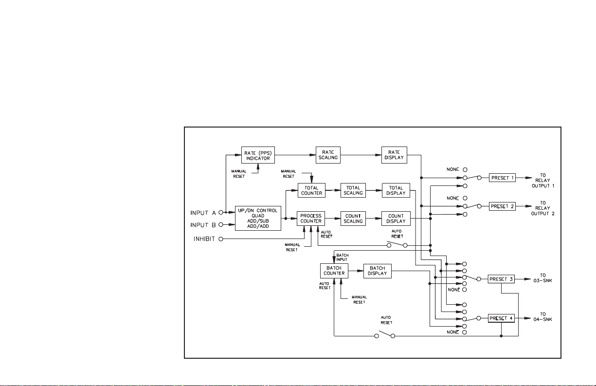
The unit contains three counters that keep track of the Process Count, Batch
Count, and Total Count. Theunit takes the actual number of pulses counted (internal
count value) and multiplies them by the Count Scale Factor and Count Scale
Multiplier. This results in the desired reading value for the Process Count display.
The Total Count is scaled by the same Count Scale Factor and Count Scale
Multiplier as the Process, and is additionally scaled by a Total Scale Factor. A Total
Scale factor of 1.0000 provides a total count that is scaled identically to the process
count. A Total Scale Factor of 0.0010 provides 1 total count for every 1000 process
counts. The Batch Count registers 1 count each time a process is completed.
During operation of the Legend Plus, after internal scaling is complete, any
digits remaining to the right of the least significant digit (LSD) of the display is
examined by the unit. If this digit is equal to or greater than 0.5, the LSD of the
display is rounded to the next higher digit. Any number less than 0.5 is ignored.
-6-
Page 9
During Reset to Preset modes of operation, any remainder greater than 0.5 will
cause the display to be rounded up. Due to this rounding action, the output
activation may appear to be delayed. In actuality the display may haverounded up
or down, but the internal count had not yet reached the preset value or zero.
The Process and Batch Counters have three Reset Action modes associated
with their displays; Reset to Zero(up-countmodes),Reset to Preset (down-count
modes), or Reset to the Counter Loadvalue. Both counters can be independently
programmed to operate in one of these reset modes. A Reset can be a manual
reset, using a programmable User Input, o r it can be one of the seven
programmableAutomaticReset modes. Both the reset action andautomaticreset
modes are programmed in the Program Counter Module.
The Process Counter displays the scaled
number of pulses in the currentBatchcycle.
The Batch counter displays the number of
processes that have been completed. When
the process count equals either preset 1 or 2
depending on the selection of the automatic
reset mode, the Batch count increments by
one. If the automaticresetmodeis disabled,
the batch counter will increment at the
preset 2 value (if Output 2 is assigned to
Process). The Batch count can also be
programmed to automatically reset.
The Total Count is the scaled total number
of counts that have been received since the
Total was last reset. It can be used to keep a
running total of process units on a desired per
shift, per day, per week, etc. basis. The Total
counter can also be used to convert the
Process Counter value to different units of
measure (i.e feet to meters, etc.). The
direction of count for the Total is dependent
on the process count direction and the Total
reset mode. The Total count can be
programmed to reset to zero, or reset topreset
3 and requiresa manual reset by a User Input.
The reset can be independent of the process
and batch count.
The signal at Input A is used for the Rate indicator. The rate indicator uses a
time interval method (1/tau) to calculate the rate value. The unit counts on the
negative edge of the input pulses. After the programmed minimum update time
elapses and the next negative edge occurs,theunitsaves the number of edges that
occurred during the elapsed time. The number of edges is multiplied by the Rate
Scale Factor, Rate Scale Multiplier, and the Rate Conversion Factor to calculate
the rate value. Averaging can be accomplished by programming the Rate
Minimum Update Time for the desired response. Extensive scaling capabilities
allow practically any desired reading at very slow count rates.
The following is a Block Diagram overview of the basic operation.
-7-
Page 10

MESSAGES
The Legend Plus features messaging capabilities that can inform the user of
output actions or other events that occur in a system. Up to ten messages can be
programmed. Messages can be requested by an output status change, User
Input(s), or through serial communications.
When a message is requested, the unit checks if there is a message already on the
display. If there are no messages on the display, the requested message is displayed.
A message on the display is replaced, if the requested messagehasthesameorhigher
priority. If the unit is not at the main display, the unit stores one message request. If
subsequent messages are requested while not at the main display, the unit stores the
last message requested, or the highest priority message requested. 2.5 seconds after
the user returns to the main display the stored message is displayed.
If a message is displayed and the user presses the appropriate key to get to the
Preset, Scaling or Programmingmenudisplay, the displayed messageis temporarily
suspended. While the message is suspended the message timer, if used, is also halted.
2.5 seconds after the user returns to the main displays, the message is redisplayed and
the message timer resumes. If the Up orDownarrow key is pressed while inthe main
display loop, the message is also suspended, and the appropriate programmed
display is shown. The message is redisplayed 2.5 seconds after the last key press.
USER INPUT MESSAGE REQUEST OPERATION
Individual User Inputs can be programmed to activate any of the tenmessages.
The messages can be maintained or momentary. Messages can be assigned a
priority from 1 to 8 (1 is highest). This assures that very important messages are
displayed first.
BINARY MESSAGE REQUEST OPERATION
Two, three or all four of the User Inputs can be configured to request messages in a
binary fashion. Messages 1 through 9 can be requested in this manner. The binary
state 0 (all binary inputs inactive), is used to indicate no message requested. During
the scanning of thebinary message request inputs, if theInput state is the sameas the
last requested binary message no change will occur. When an input change occurs,
the unit requests the message number corresponding to the state of the inputs. The
inputs must be stable for 100 msec (debounce time) for the message to be requested
(See Program User Module for more details). Changing the individual binary
message request input linesslowly will cause unwanted message requests, if several
bits need to be changed. This would be noticeable on the display, if a user was
utilizing a thumbwheel switch to change between messages.
OUTPUT MESSAGE REQUEST
Each output can be individually programmedto request a specific message when
activated. The appropriate message will be requested regardless of the method used
to activate the output, i.e. User Input, Count/preset processing, serial command,etc.
Note: The Output must be active for a minimum of 50 msec. for the request to be seen.
MESSAGE CANCELLATION
Messages can be cancelled automatically, or manually. When cancelled,
messages programmed for maintained request, willbe re-requested if thedisplay
is available and the request source is still active. A request for a message of the
same or higher priority will cancel the current message on the display. Messages
can also becancelled by a User Input programmed for Cancel Message or via the
serial port. The three programmable cancellation options are Latched, Timed,
and Til End. (See Program User Message Cancellation for details).
-8-
Page 11
OVERFLOW INDICATION
The unit flashes the word “OVERFLOW” (or assigned mnemonic) in the
appropriate display when an overflow condition occurs. An overflow occurs if the
capacity of the display (6-digits Process& Batch, 8-digits Total) is exceeded orif the
internal count capacity (9-digits Process, 7-digits Batch, 11-digits Total) is
exceeded. The use of anextremelysmallScale Multiplier and Scale Factor valuecan
cause the internal count capacity to overflow before the displayed value overflows.
For example, if a Scale Factor of 0.0001 and a Scale Multiplier of 0.001 is
used, for every 10,000,000 count edges received, the display increments by 1.
Before the display reaches 215, the internal counter overflows. When the
capacity of the display is exceeded, the count value is maintained and is valid. If
the internal count capacity is exceeded, the count value is no longer valid.
Use of a Scale Factor larger than “1” can cause the displayed Process or Total
value to overflow before 999,999 counts are accumulated. The use of a Rate
Scale Factor, Scale Multiplier, and Rate Conversion Factor larger than “1” can
cause the rate display to be in an overflow condition.
The counters should not be allowed to operate in an overflow condition. As
soon as, or beforethe counters overflow, the informationshould be recorded and
the counters reset.
PEAK & VALLEY
The Peak and Valley registers record the lowest (Valley) and the highest
(Peak) readings of the rateinputsignal. These values are viewed inthe indication
display loop and are updated automatically. A User Input can be programmed to
reset the values to the current rate value individually or by sending the proper
command via the serial communication port. The Peak and Valley values are
NOT retained when power to the unit is removed.
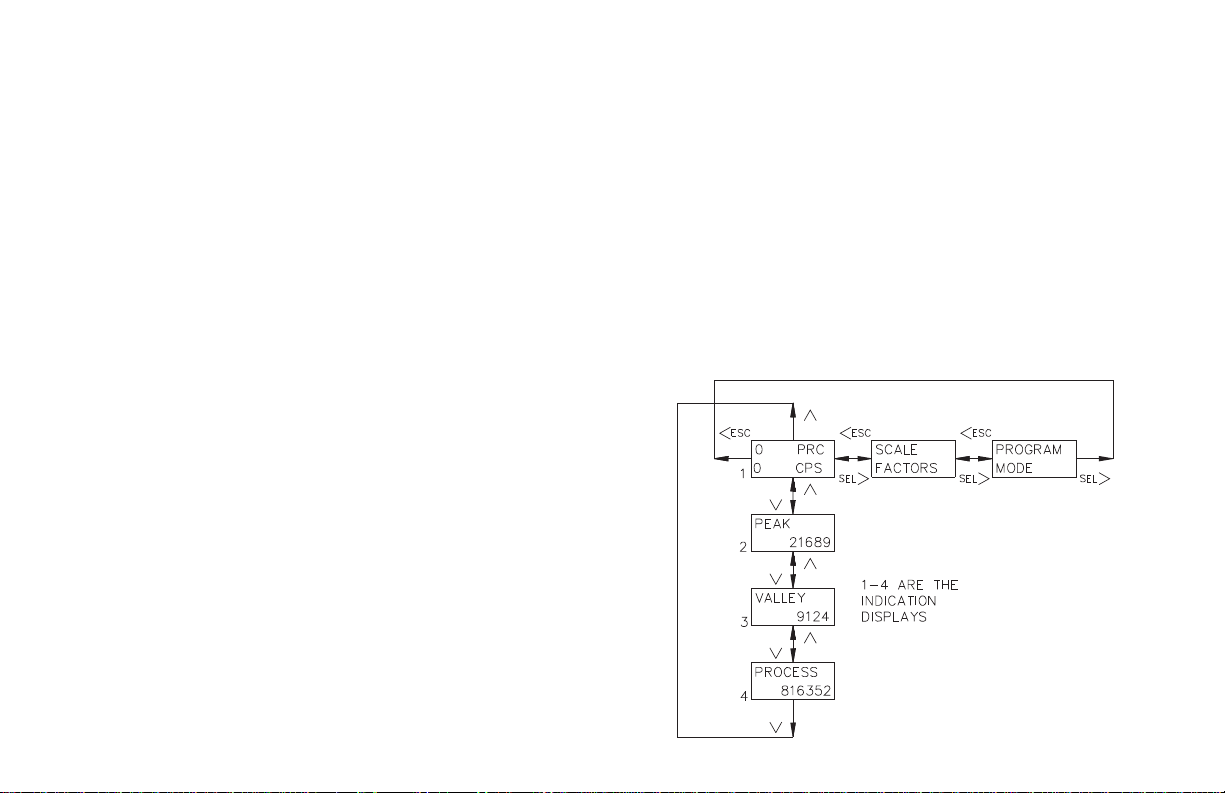
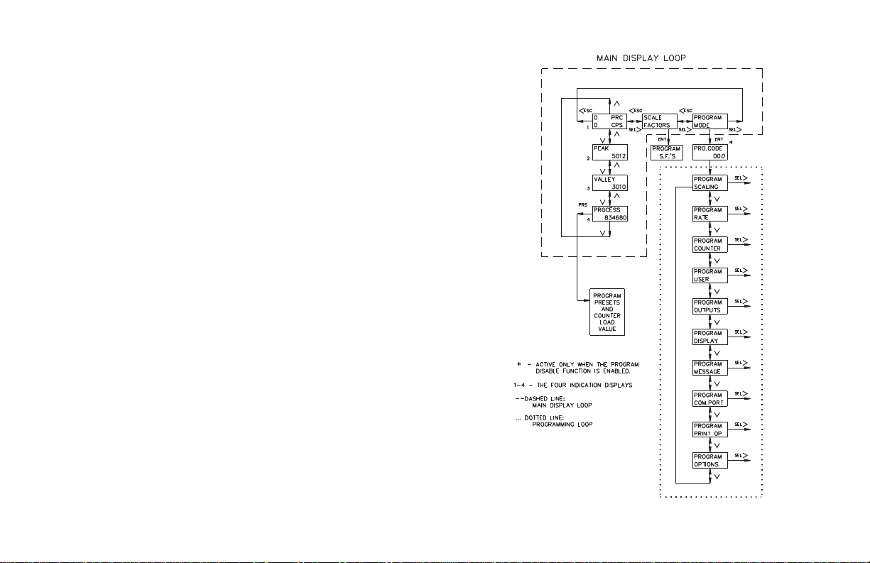
NORMAL OPERATING MODE
In the normal operating mode, the up, down, left, and right arrow keys are used
to scroll through the main display loop. In the main display loop, the four
indication displays, scale factors, and program mode modules are viewed, as
shown at right. In the indication display loop, the up and down arrow keysare used
to scroll to each display. The indication displays are referenced as 1 (0 PRC/0
CPS), 2 (PEAK), 3 (VALLEY), and 4 (PROCESS), which are the factory default
settings. The indication displays canbe programmedto show other parameters and
automatically scroll (See Program Displays Module). The last indication display
that was viewed at power down, is the one viewed on power up.
The Presets and Counter Load values are accessed from any of the indication
displays or from the programmingloop.The Count, Rate, and Total scale factors
are accessed from the Scale Factors display or when in the programming loop
from the Program Scaling module. In the Program Mode display, the operator
enters the programming loop to access all parameters to configure the unit.
Shown below is the Main Display Loop.
-9-
Page 12

KEYPAD DESCRIPTION
The keypad has a key array of two rows by four
columns. Some keys have a dual function. For a
description of key functions during text and
mnemonics editing, see Text Editing in the
Program Message Module. The following is a
description of each key and its function during
programming and normal operation:
KEYPAD FUNCTIONS
F1
- Function key F1 is aUserProgrammable Input. Whenthekeyis pressed,
the unit performs the appropriate function as programmed in the
“Program User Module”.
- Function key F2/RST is a User Programmable Input. When the key is
F2
RST
PRS
<ESC
^
pressed, the unit performs the appropriate function, as programmed in
the “Program User Module”. The “RST” printing on this key is used as
a quick reference for the operator if the function key is selected for a
reset function.
- The PRS key accesses the Preset and Counter Load Module provided
these values are not programmed for ‘loc’k. If all values are ‘loc’ked,
pressing the PRS key does nothing. Preset values that are accessible
(changeable), can be changed immediately. Pressing the SEL> key is
no longer necessary to edit preset values. Within the preset menu,
pressing this key saves the value and advances the display to the next
available preset. Pressing the PRS key attheend of the module exits the
module and returns the user to the main display loop.
- The Left arrow/escape key scrolls to the left in the main display loop.
When programminganumericalvalue,itselectsthedigitto the left. In a
sub-menu, it exits to the next higher level menu in the loop. It is also
used to exit the programming loop. When exiting the programming
loop, the unit stores all parameters in non-volatile memoryand returns
to the last viewed indication display.
- The Up arrow key scrolls through the indication displays. In the
programming loop, this key can be used to scroll through the main
menus. When programming a numerical value, it increments
(decrements, i.e., goes more positive, for negative values) at the
selected digit position.
KEYPAD FUNCTIONS (Cont’d)
If the key is pushed and held, the value will scroll (count up)
automatically. After 5 counts, the unit enters fast scroll mode. If the
key remains pushed, a digit shift occurs every one hundred counts
until the maximum value or zero (for negative presets) is reached.
When the digit shift occurs, the previously scrolling digit goes to
zero. When zero is reached (for negative values), the display holds at
zero. To go positive, the key must be released and pushed again.
- The Down arrow key scrolls through the indication displays. In the
v
ENT
SEL>
programming loop, it scrollsthrough the mainmenus and sub menus.
When programming a numerical value, it decrements (increments or
goes more negative, for negative values)at the selected digit position.
If the key is pushed and held, the value will auto scroll (count down
automatically). After 5 counts, the unit enters fast scroll mode. If the
key remains pushed, a digit shift occurs every one hundred counts
until zero is reached. When the digit shift occurs, the previously
scrolling digit goes tozero. When zero is reached,the display holds at
zero. To go negative, the key must be released and pushed again.
- The Enter key enters the programming loop, when “Program Mode” is
displayed from the main display loop. When “Scale Factors” is
displayed, pressing Enter allows access to the scale factors. This keyis
also used to save changes to data values. If the data value is a preset or
counter load value, the value is entered and the preset menu is exited.
For all other numeric data values (i.e., Output time, Rate update times,
etc.), the value isentered and the value edit mode is exited. The value is
still viewed in the display, but with no digits flashing.
- The Select/Right arrow key scrolls right in the main d isplay loop.
When programming a numericalvalue, it selects the digit to the right.
In a sub-menu loop, it is used to go to the next lower level and
eventually into an edit menu.
-10-
Page 13

PROGRAM CODE NUMBER (PRO.CODE)
In two of the Program Disable states, it is necessary to enter the PRO.CODE
number before gaining access to the programming menus. The default value for
the code is “00”, but should b e programmed differently (See Program Options
Module). This helps prevent inadvertententry into the unit programmingmenus.
The PRO.CODE prompt is viewed when PROGRAM MODE is displayed and
the enter key ispressed. At this time,the Code Number must be entered using the
arrow keys. If the wrong code number is entered, the operator will NOT be able to
enter the programming loop and the unit returns to the main display loop.
FRONT PANEL ACCESSIBLE FUNCTIONS WITH PROGRAM
DISABLE
The Legend Plus has several ways to limit the programming of parametersfrom
the front panel keypad. The Operator Access section of the Program Options
Module is used with the Program Disable (PGM.DIS.) DIP switch and aUserInput
selected for PGM.DIS to limit programming. To enter the programming loop, a
code number may need to be entered, depending on the Program Disable setting.
Only an external User Input can be selected for Program Disable. The following
list describes the possible program disabling settings.
PGM.DIS.
SWITCH
OFF INACTIVE or Not
OFF ACTIVE 0 to 98 Operator Accessible Functions
OFF ACTIVE 99 Operator Accessible Functions
ON INACTIVE or Not
ON INACTIVE or Not
ON ACTIVE ALL Operator Accessible Functions
Note: If the User Input, set for PGM.DIS., is changed to another function, make
sure the User Input is not low (active). If the input is low when the function is
changed, the program disable function is still active for the User Input.
USER INPUT
TERMINAL
Programmed for PGM.DIS
Programmed for PGM.DIS
Programmed for PGM.DIS
PROGRAM
CODE
NUMBER
ALL All programming enabled.
Enabled, Programming Loop
Accessible via code number.
Enabled, ProgrammingLoop Disabled.
0 to 98 Operator Accessible Functions
Enabled, Programming Loop
Accessible via Code number.
99 Operator Accessible Functions
Enabled, ProgrammingLoop Disabled.
Disabled, Programming Loop
Disabled.
ACTION
-11-
Page 14
PROGRAMMING GENERAL DESCRIPTION
Programming of the Legend Plus is done through the front panel keypad, which
allows the user to enter into Main Menus, Sub-Menus, and Edit Menus. English
language prompts, flashing parameter values, and the front panel keypad aid the
operator during programming.
Although the unit has been programmed at the factory, the parameters generally
have to be changed to suit the desired application. The Main Menus are entered by
pressing the enter (ENT) key when Program Mode is displayed. From Main Menus,
the u ser can enter a Sub-Menu where parameter values can be viewed. From the
Sub-Menu, the operator can advance into an Edit Menu, where a parameter value is
changed and entered. There are three types of Edit Menus:
1. A Choice Edit Menu allows the operator to scroll through options by repeatedly
pressing the down arrow key until the desired option is viewed. The option is
selected by pressing the ENT (enter) key, which returnstheoperatortothe previous
sub-menu. The operator can exit the Edit Menu WITHOUT making a selection by
pressing the <ESC key, which returns the operator to the previous sub-menu.
2. In a Numerical Value Edit Menu, the operator uses the left or right arrow key to
select a digit. The up and down arrow keys change the digit’s value. The PRS key
toggles the left-most digit between a minus (-) and a zero for plus (+), for that
numeric value. When the appropriate numerical value is selected, it is entered by
pressing the ENT key, which returns the operator to the previous sub-menu.
3. A Text Edit Menu is where messages are programmed, and changes are made to
mnemonics and custom display lines. The up and down arrow keys are used to
scroll through characters. The function keys are used with the up and down arrow
keys to toggle between upper and lower case letters and to togglebetween standard
and extended character sets. A complete listing of key functions in a Text Edit
menu can be found in the Program Message Module.
All parameter values changed in the Programming Loop are saved when exiting the
loop. The operator can exit the programming loop from any of the main menus by
pressing the <ESCkey. When the <ESC key is pressed, the display momentarily shows
“Please Wait...”, while theparametervalues are saved in non-volatile memory.The unit
returns to the indication displaythat was last viewed. Shown arethe Main Display Loop
and the Main ProgrammingmenusoftheFourPresetBatchLegendPlus(LGPB)unit.
All following flow charts have slanted characters to show parameters that are
flashing in the unit’s display and have programmable options.
-12-
Page 15
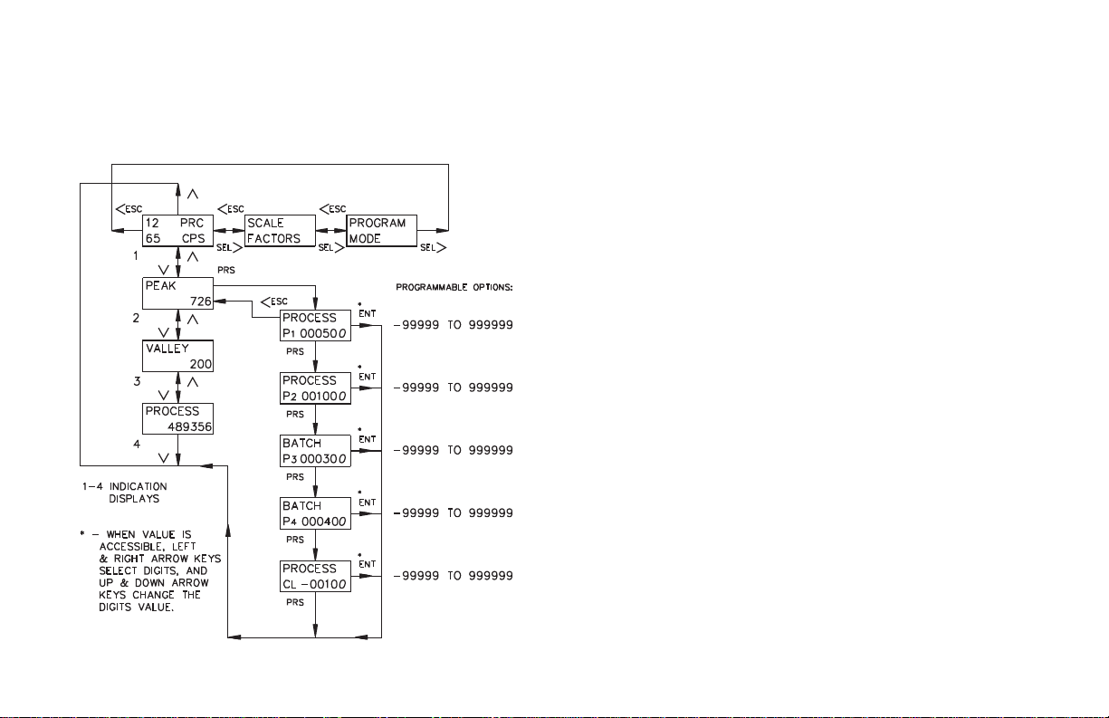
PROGRAM PRESETS & COUNTER LOAD MODULE
The Preset and Counter Load values are accessed from any of the indication
displays, or fromanyof the main menusin the programmingloop,bypressingthe
PRS key. The top line indicates which display the preset is assigned to. The
bottom line indicates which preset is viewed and the programmed value. The
following flowchart shows only the Preset and Counter Load portion:
PRESET VALUES
Preset values P1 and P2 can activate relay outputs one and two respectively,
when the display value equals the preset value. All outputs (presets) can be
assigned to the process count, rate indication display, or none. Presets P3 and P4
can activate solid state outputs O3-SNK & O4-SNK respectively, when the
assigned display equals the preset value. Only outputs three and four can be
assigned to the Batch Counter, or Total Counter. The output action (timed,
latched, or boundary) is programmed in the Program Outputs Module. The preset
values may range from -99,999 to 999,999.
The Count Scale Factor, has a direct effect on the preset value entered, when
the output (preset) is assigned to a counter display. For a Scale Factor Value
greater than “1”, the preset value should be a whole number multipleof the Scale
Factor value. If it is not, the unit automatically adjusts the preset value up or down
to force it to be evenly divisible by the Scale Factor.
COUNTER LOAD VALUE
The Counter Load (CL) value allows the user to start the process or batch
count value from a value other than zero or a preset. The Process and Batch
display reset mode is set in the Program Counter Module. The Counter Load
value can be programmed from -99,999 to 999,999. The Counter Load value is
assigned to the process Counter unless otherwise programmed.
-13-
Page 16
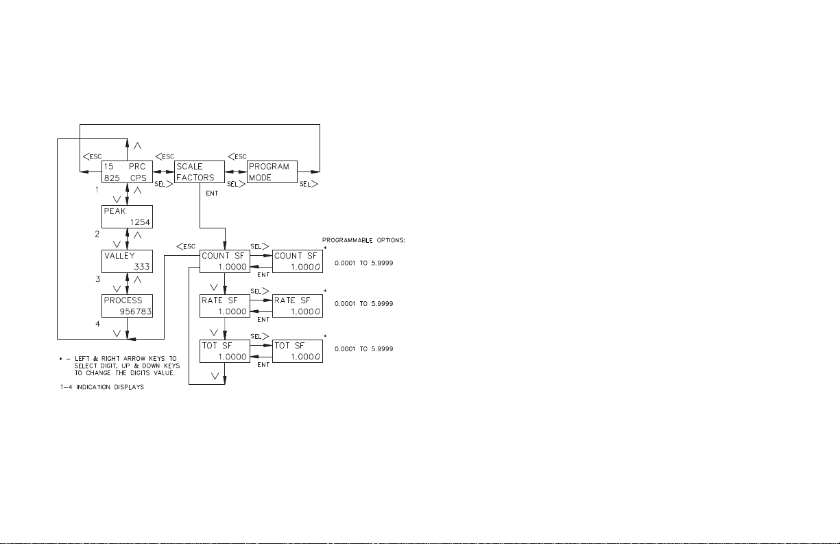
PROGRAM SCALE FACTORS MODULE
The Scale Factors are accessed from the Scale Factors Module in the main
display loop or from the Scaling Module in the programming loop. Since the
Scale Factors may need to be changed periodically, this module allows the
operator to change a Scale Factor value WITHOUT entering the programming
loop. The following flowchart shows only the Scale Factor portion:
COUNT SCALE FACTOR
The number of pulses counted (internal count value) is multiplied by the
Count Scale Factor value and the Scale Multiplier to obtain the desired Process
Count display value. A Count Scale Factor value of 1.0000 and a Scale
Multiplier of “1” results in the display of theactual number of input pulses that
were counted. The Count Scale Factor value is used for converting the number
of pulses counted tothe required units of measure for thedisplay. This includes
conversion from different units of measure (i.e feet to meters,etc.). The Count
Scale Factor value can range from0.0001 to 5.9999. It is importantto note that
the precision of a counter application cannot be improved by using a Scale
Factor greater than “ 1”. To accomplish greater precision, more pulse
information must be generated per measuring unit. For details, refer to Scaling
for Count and Total Indication in the Appendix.
RATE SCALE FACTOR
The internal rate value (pulses per second) is multiplied by the Rate Scale
Factor, Rate Scale Multiplier, and Rate Conversion Factor values, to obtain the
desired rate display value. The Rate Scale Factor value is usedfor converting the
internal rate to the required units of measure for the d isplay. This includes
conversion from different units of measure (i.e feet to meters, etc.). The Rate
Scale Factor Values range from 0.0001 to 5.9999. Due to the way the rate is
calculated, high resolution and accuracy are achieved at all input rates. For
details, refer to Scaling for Rate Indication in the Appendix.
TOTAL SCALE FACTOR
The number of pulses counted (internal total count value) is multiplied by the
Count Scale Factor, the Scale Multiplier, and the Total Scale Factor to obtain the
desired Total display value. A value of 1.0000 results in the same scaling as the
Process Count display. The Total Scale Factor value is used for converting the
number of pulses counted to the required units of measure for the Total display.
This includes conversion from different units of measure (i.e feet to meters, etc.).
The Total Scale Factor value can range from0.0001 to 5.9999. Fordetails, refer
to Scaling for Count and Total Indication in the Appendix.
-14-
Page 17
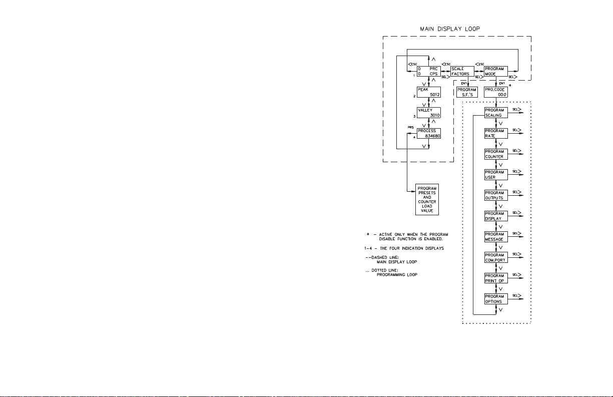
PROGRAMMING MENUS
The programming menus are accessed when “Program Mode” is displayed in
the main display loop. All parameter values can be accessed from the Main
Programming Menus. Accessibility to the programming menus depends on the
Program Disable Function setting (See Front Panel Accessible Functions with
Program Disable) and could require a Program Code number to enter the
programming menus.
In the programming menus, pressing the up ordown arrow key scrolls through
the main menus. From the Main Menu, a sub-menu is accessed by pressing the
SEL> key. In a sub-menu, the operator can view the parameter values that are
currently selected. To change a parameter value, the edit menu is accessed by
pressing the SEL> key (See Programming General Description section).
The Preset and Counter Load module can be accessed from any Main
ProgrammingMenu by pressing thePRS key. When exiting thepreset and counter
load module, the unit returns to the last main menu that was viewed.
When all parameter changes have been made, the operator can exit the
programming loop, from any main menu, by pressing the <ESC key. Exiting
saves all parameter values and returns the unit to the last indication display that
was viewed. Shown are all of the main programming menus:
-15-
Page 18
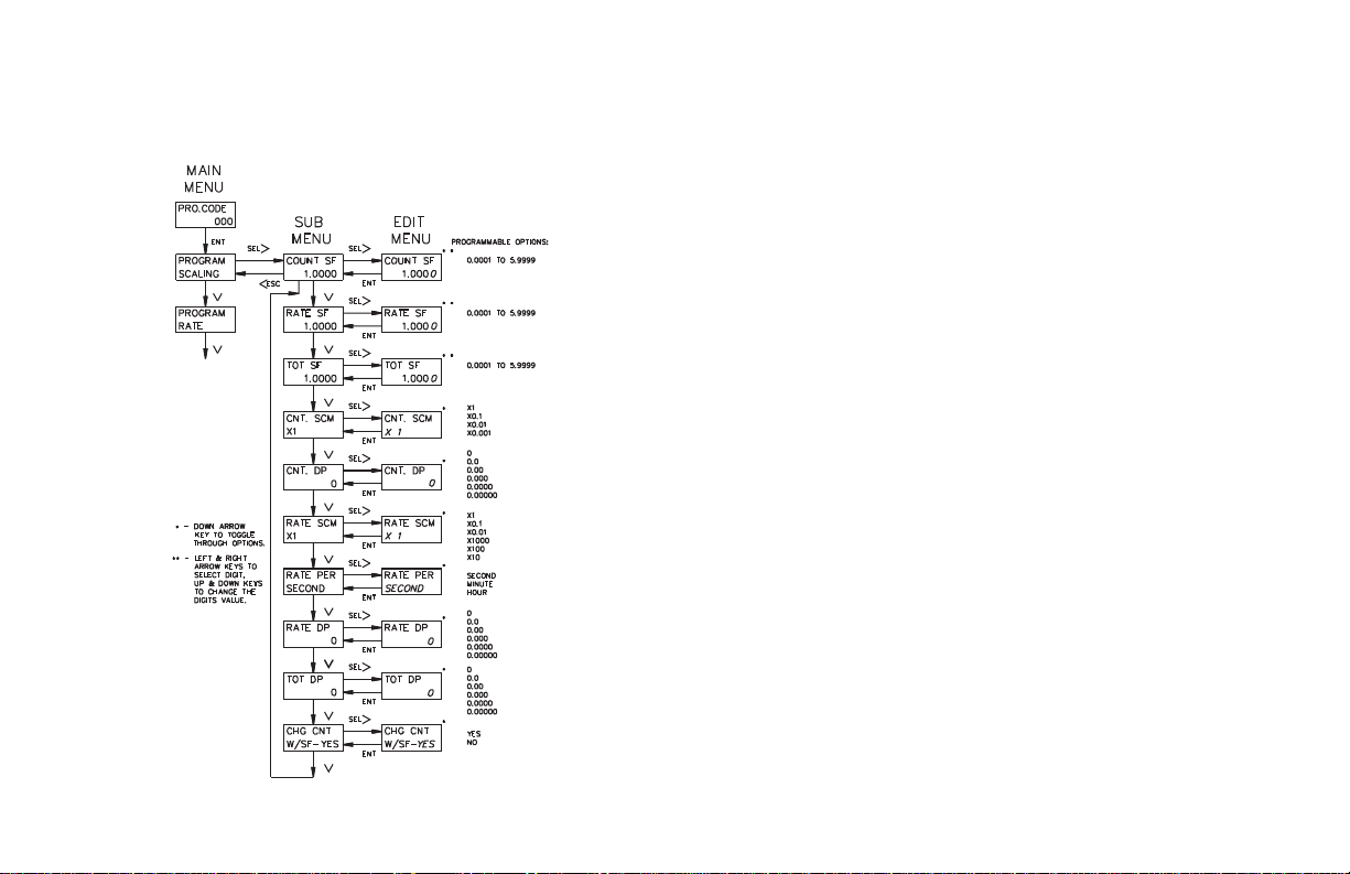
PROGRAM SCALING MODULE
In the scaling module, the Count, Rate, and Total Scale Factors, scale
multipliers, rate conversion factor, and decimal points are accessed. The
following flowchart shows only the Scaling portion:
COUNT SCALE FACTOR (COUNT SF)
The Count Scale Factor Value can range from 0.0001 to 5.9999. See Program
Scale Factors Module for detailed description.
RATE SCALE FACTOR (RATE SF)
The Rate Scale Factor Value can range from 0.0001 to 5.9999. See Program
Scale Factors Module for detailed description.
TOTAL SCALE FACTOR (TOT SF)
The Total Scale Factor value can range from 0.0001 to 5.9999. See Program
Scale Factors Module for detailed description.
Note: Since the Process, Total and Rate Scale Factors, may need to be changed
periodically, they can also be accessed from the Scale Factors Module in the
main display loop.
COUNT SCALE MULTIPLIER (CNT.SCM)
There are four Count Scale Multipliers available; X 1, X 0.1, X 0.01, or X
0.001 that change the Process count display value accordingly. The number of
pulses counted (internal countvalue) is multiplied by thescale multiplier and the
scale factor values to obtain the desired Process Count display.
Note: Use of a small scale multiplier with a small scale factor could cause the
internal count value to be exceeded before the 6-digit display value is exceeded.
RATE SCALE MULTIPLIER (RATE SCM)
The Rate Scale Multiplier isused with the rate scale factorand rate conversion
factor to scale the rate display value for the proper units of measure. The scale
multipliers available are; X 1, X 0.1, X 0.01, X 1000, X 100, or X 10.
RATE CONVERSION FACTOR (RATE PER)
The Rate Conversion Factor is used to display the rate value in the proper
time units of measure, per second (X1), per minute(X60), or per hour (X3600)
for the Rate display.
-16-
Page 19

DECIMAL POINT (CNT. DP, RATE DP, TOT DP)
There are six Decimal Point locations available fortheRate, Total and Process
displays. The decimal point position is programmed individually for each
display. The decimalpoint location programmed f or the Rate display is the same
for the Peak and Valley displays.
CHANGE COUNT VALUE WITH SCALE FACTOR (CHG CNT W/SF)
Any changes to the count or total scale factorsadjustthecurrentlydisplayedcount
and total values to reflect the new scale factor. If this option is set to no, the internal
count value is modified so that the count and total display values are not affected.
Example; a count scale factor of 1.000 with a count value of 36 and a total
value of 4 is changed toacount scale factor of 0.500. If the optionisset to yes, the
new count value would be 18 and the newtotalvalue,2.If the option was selected
as no, the count and total display values would remain at 36 and 4.
-17-
Page 20
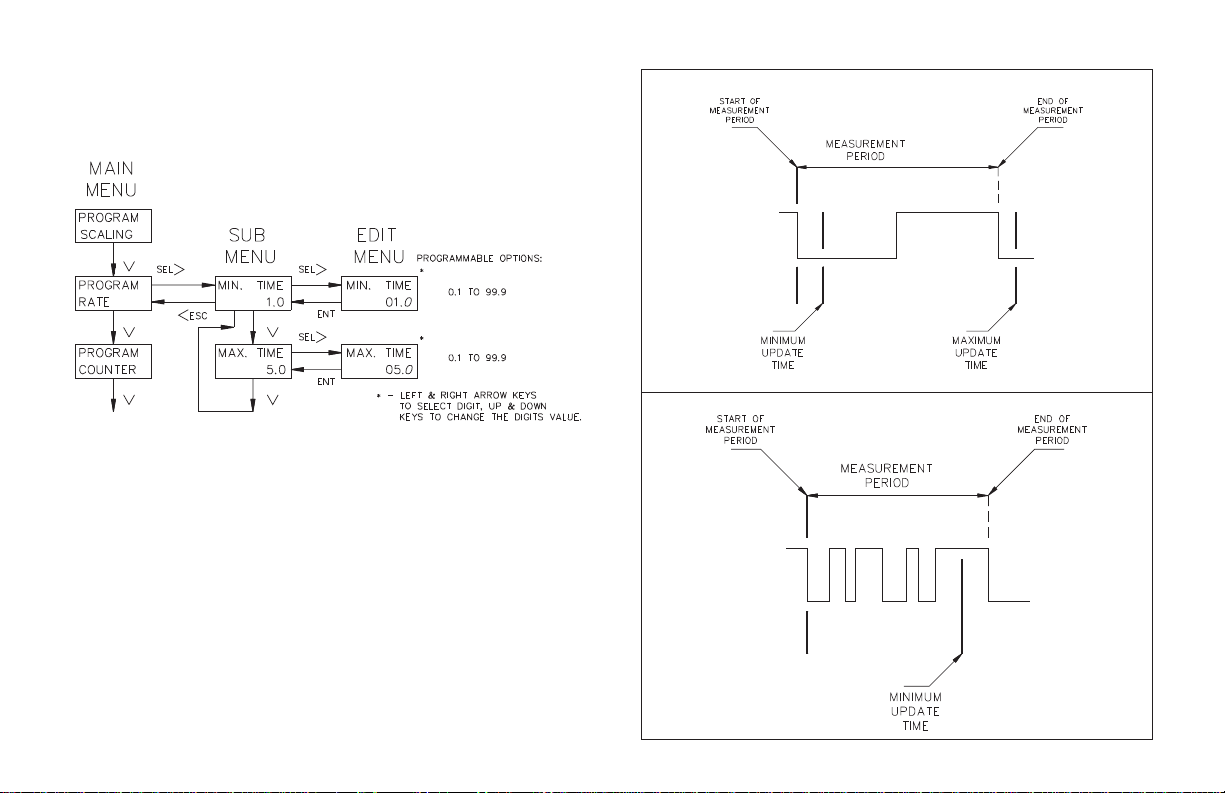
PROGRAM RATE MODULE
MINIMUM AND MAXIMUM UPDATE TIME
The Minimum and Maximum Update Times are programmed in the Rate
module. The update times can range from 0.1 to 99.9 seconds. The following
flowchart shows only the Rate portion:
The Rate value is calculatedusing the time measured between thefirst and last
pulse as the measurement period. The measurement period ends when the
minimum update time has expired, and the next negative edge occurs. The
number of pulses that occurred during the measurement period are counted and
multiplied by the rate scale factor, scale multiplier, and rate conversion factor.
The result is divided by the actual measurement period to obtain the rate display
value. If the unit does not receive a negative edge within the period between the
minimum update time and the maximum update time from the start of the
measurement period, the time period ends and the rate display goes to zero. At
very slow count rates the measurement period is the actual period of one count
cycle, as long as the input rate frequency is not longer than the maximumupdate
time. The rate indicator only uses the falling edge of the Input A signal.
Note: The minimum update time must be equal to or less than 65536 divide by the
maximum operating frequency (in Hz) or the internal rate counter will
overflow. For example: If the maximum operating frequency is 10 KHz, the
minimum update time must be less than 6.5 sec (65,535 ¸ 10,000 = 6.5).
BASIC TIMING DIAGRAMS FOR RATE OPERATION
ONE COUNT CYCLE MEASUREMENT
AVERAGE CYCLE MEASUREMENT
-18-
Page 21
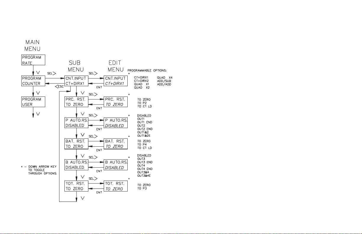
PROGRAM COUNTER MODULE
In the Counter Module, the count mode, reset action, and automatic reset
capability are selected. The following flowchart shows only the Counter portion:
COUNT MODES (CNT. INPUT)
There are seven available count modes. User Input 4 programmed for the
count Inhibit function can be used with any count mode. Input A signal is used for
the count and rate input. Input B is used in combination with Input A for Count
Control Direction, Quadrature counting, Anti-coincidence Add/Subtract or
Anti-coincidence Add/Add counting applications.
CT+DIRX1 (X1 COUNTING WITH DIRECTION)
The unit counts one count on every negative edge of theinput signal at Input
A. The direction of the count isdetermined by the logic state of Input B.A high
level at Input B causes the unit to count in a positive direction. A low level
causes the unit to count in a negative direction. The rate display is NOT affected
by the logic state of Input B.
CT+DIRX2 (X2 COUNTING WITH DIRECTION)
The unit counts one count on every negative edge of the input signal and one
count on every positive edge ofthe input signal at Input A. Inthis mode,the input
signal is effectively doubled. The direction of the count is determined by the
logic state of Input B.A high level at InputB causes the unit to countin a positive
direction. A low level causes the unit to count in a negative direction. The rate
display is NOT affected by the state of Input B.
QUAD X1 (QUADRATURE X1)
Quadrature counting modes are primarily used in positioning and anti-jitter
applications. This mode works due to the manner in which the two incoming
pulses are positioned relativeto each other. The pulsesignal on Input B isshifted
90º away from the pulsesignal at Input A. These twosignals are processed by the
Legend Plus as follows:
Input A serves as the count and rate input, while Input B serves as the quadrature
input. For quadrature with single edge counting, the counter counts in a positive
direction when Input A is a negative going edge and Input B is at a low level. The
counter counts in a negative direction when Input A is a positive going edge and
Input B is at a low level. All transitions on Input A are ignored when Input B is at a
high level. These logic rules provide the basis foranti-jitteroperationwhich prevents
false counts from occurring due to back-lash, vibration, chatter, etc.
-19-
Page 22

COUNT MODES (CNT.INPUT) (Cont’d)
QUAD X2 (QUADRATURE X2)
When two edge counting is used, the quadrature mode works the same as with
single edge counting when Input B is low. But when Input B is a high level,
counts at Input A are no longer ignored. Instead, the logic rules for Input A are
complemented, allowing both edges of Input A to be counted. This doubles the
effective resolution of the encoded input.
QUAD X4 (QUADRATURE X4)
This mode takes the quadrature mode, with two edge counting, one step
further. In quadrature times 4, both Input A and Input B serve as the count or
quadrature input, depending on their state. In one instance, Input A serves as the
count input and Input B serves as thequadrature input. In another instance, Input
A is the quadrature input and Input B is the count input. This enables each edge,
positive and negative going, of both inputs, A and B, to be counted. This results
in a resolution four times greater than in the basic quadrature X1 mode.As in the
other modes, Input A is also used for the rate input.
ADD/SUB (TWO INPUT ANTI/COINCIDENCE ADD/SUBTRACT)
This mode effectively separates count pulses that may simultaneously appear
at the two inputs. The Legend Plus processes the count pulses into a string of
time-separated pulses, so the internal counter does not miss any count pulses.
Input A serves as the add input (count increments) and Input B serves as the
subtract input (count decrements).
ADD/ADD (TWO INPUT ANTI/COINCIDENCE ADD/ADD)
This mode effectively sums count pulses that may simultaneously appear at
the two inputs. The Legend Plus processes the count pulses into a string of
time-separated pulses so the internal counter does not miss any count pulses.
Input A serves as an add input (count increments) and Input B serves as an
additional add input (count increments).
PROCESS RESET ACTION (PRC. RST.)
The Process count display can be reset to Zero, Preset 2, or to the Counter Load
value. The display can be reset automatically or by aUserInput.AUser Input can
be programmedfor a Maintained or Momentary reset (See Program User Module
for details). Automatic reset is covered in the next section.
RESET TO ZERO
The Process Counter Display value returns to Zero.
TO P2 (PRESET 2)
The Process Counter Display value returns to the Preset 2 value. Output 2
triggers when the count reaches zero.
TO CT LD (COUNTER LOAD)
The Process Counter Display value returns to the Counter Load value.
Note: The Counter Load reset action should be programmed for only one count
display, either the process count or the batch count.
PROCESS AUTOMATIC RESET (P AUTO.RS)
The Automatic reset mode can be enabled or disabled. The Process Counter
display automatically resets to the programmed reset action, when one of the
automatic reset modes is selected. A manualresetby a User Input causes thecount to
reset regardless of the automatic reset mode. The following choices are available:
OUT1 (Reset at Beginning Of Output 1)
The counter resets when the count equals the preset 1 value. Output 1 can be
timed or latched.
OUT1END (Reset at End Of Timed Output 1)
The counter resets after output 1 has timed out.
OUT2 (Reset at Beginning Of Output 2)
The counter resets when the count equals the preset 2 value or zero (Reset to
P2). Output 2 can be timed or latched.
OUT2END (Reset at End Of Timed Output 2)
The counter resets after output 2 has timed out.
OUT1&2 (Reset at Beginning Of Output 1 or Output 2)
The counter resets when the count equals preset 1, preset 2,or zero (reset to
P2). Outputs 1 and 2 can be Timed or Latched.
OUT1&2E (Reset at End Of Timed Output 1 or Output 2)
The counter resets after output 1 or output 2 has timed out.
Notes:
1. For Auto Reset modes, when operating between approximately
count rate, all other presets should not occur within1 to 6 counts following the
count value at which Auto Reset occurs. In Reset to Zero modes with positive
preset values, this would apply to count values between 0 and 6. For Reset to
-20-
1
to maximum
2
Page 23

Preset or Counter Load modes, it would apply to preset value between 0 to 6
less than the Preset 2 value (when positive).
2. For Auto Reset modes, no other count presets should be set to the same count
value at which Auto Reset occurs (Preset 2 or Zero for Reset to Preset or
Counter Load mode). If they are, only the auto reset output will activate. If the
process counter is set to Auto Reset at OUT1 & 2, and other Presets are the same
as Preset 2 (or Zero for Reset to Preset mode), only Output 2 will activate. If the
unit is set to Auto Reset at OUT1, only Outputs 1 and 2 will activate.
BATCH RESET ACTION (BAT. RST)
The Batch count display can be reset to Zero, Preset 4, or to the Counter Load
value. The display can be reset automatically or by a User Input. Reset by User
Input can be a Maintained or Momentary reset (See Program User Module for
details). Automatic reset is covered in the next section.
TO ZERO
The Batch Counter Display value returns to zero.
TO P4 (PRESET 4)
The Batch Counter Display value returns to the Preset 4 value. Output 4
triggers when the count reaches zero.
TO CT LD (COUNTER LOAD)
The Batch Counter Display value returns to the Counter Load value.
Note: The Counter Load reset action should be programmed for only one count
display, either the process count or the batch count.
BATCH AUTOMATIC RESET (B AUTO. RS)
The Automatic reset mode can be enabledor disabled. The Batch Counterdisplay
automatically resets to the programmedresetaction, when one of theautomatic reset
modes is selected. A manual reset by a User Inputcausesthe count to reset regardless
of the automatic reset mode. The following choices are available:
OUT3 (Reset at Beginning Of Output 3)
The batch counter resets when the count equals the preset 3 value. Output 3
can be timed or latched.
OUT3END (Reset at End Of Timed Output 3)
The batch counter resets after output 3 has timed out.
OUT4 (Reset at Beginning Of Output 4)
The batch counterresets when the count equals preset 4, or zero (Reset to P4).
Output 4 can be timed or latched.
OUT4END (Reset at End Of Timed Output 4)
The batch counter resets after output 4 has timed out.
OUT3&4 (Reset at Beginning Of Output 3 or Output 4)
The batch counter resets when the count equals preset 3, preset 4, or zero
(Reset to P4). Outputs 3 and 4 can be Timed or Latched.
OUT3&4E (Reset at End Of Timed Output 3 or Output 4)
The batch counter resets after output 3 or output 4 has timed out.
TOTAL RESET ACTION (TOT. RST.)
The Total count display can bereset to Zero, or to Preset3.Output 3 must be set to
Total for P3 to be selected.The method of reset is by UserInput. The User Input can
be set for a Momentaryor Maintained reset (See ProgramUserModulefordetails).
TO ZERO
The Total Count Display value returns to Zero. In this mode, the Total count
direction is up.
TO P3 (PRESET 3)
The Total Count Display value returns to the Preset 3 value. Output 3 triggers
when the count reaches zero. In this mode, the Total count direction is down.
-21-
Page 24

PROGRAM USER MODULE
There are six User Input; four external User
Inputs, and two front panel Function keys, which
have various programmable capabilities. An
external User Input is active when tied to common.
A front panel function key is active when pressed.
The options for each User Input are the same,
except as noted below:
1. The two Function keys (F1 & F2/RST) DO NOT
have the Program Disable (PGM.DIS.) option.
2. Only User Input 4 has the Inhibit Function.
The operator can select only one option for each User
Input. The operator mayhave to entera second sub-menu
for some options before entering the edit menu. The
following flowchart shows only the user portion:
BINARY MESSAGE REQUEST (BIN MSG REQ)
Two, three, or all four of the external User Inputs can be
configured as binary message request inputs. When
configured as binary message request inputs, the individual
user input options are not displayed or available. The inputs
are active when pulled low (to common). In order for a
message to be requested, the inputs must remain stable for
100 msec minimum. The number of messages that can be
requested varies with the mode (# ofbits) selected; for 2bit 3 messages, 3bit - 7 messages, 4bit - 9 messages. Message
#0 cannot be requested, since binary state 0 is used to
indicate no request.
Example: If the Legend Plus is set up for 2 bit Binary
Requests, User Inputs 1 and 2 do not appear in the
Program User loop for programming. Activating User
Input 1 displays Message 1, and activating User Input 2
displays Message 2. Activating both together displays
Message 3. Changing the individual binary message
request inputs slowly may cause unwanted message
requests, if several bits need to be changed.
-22-
Page 25

USER INPUT NUMBER (0=INACTIVE, 1=ACTIVE) MESSAGE
43 2 1
0 0 0 0 NONE
0 0 0 1 MESSAGE #1
0 0 1 0 MESSAGE #2
0 0 1 1 MESSAGE #3
0 1 0 0 MESSAGE #4
0 1 0 1 MESSAGE #5
0 1 1 0 MESSAGE #6
0 1 1 1 MESSAGE #7
1 0 0 0 MESSAGE #8
1 0 0 1 MESSAGE #9
REQUESTED
USR.IN 1-4
NO MODE
If a User Input terminal or a Function key is activated, it is ignored.
MAINTAINED RESET (MNT RST)
Maintained reset has six selectable options. Any or all can be selected in the
edit menu by selecting YES or NO using the UP and DOWN arrow keys.
RATE: Resets the measurement period. The Rate display value is the last
reading obtained before the reset. The next reading occurs after the
release of thereset and the expiration of the measurementperiod. The
Rate display does not reset to zero.
PEAK: Resets the Peak value to the current rate value.
VALLEY: Resets the Valley value to the current rate value.
PROCESS: Resets the process count value according to the programmed
reset action.
BATCH: Resets the batch count value according to the programmed reset
action.
TOTAL: Resets the total count value according to the programmed reset
action.
With Maintained reset, the value continuously resets as long asthe User Input
or Function Key is active. Maintained reset is level sensitive and overrides an
automatic reset mode.
MOMENTARY RESET (MOM RST)
Momentary reset has the same six selectable options as Maintained Reset.
With Momentary reset, the value resets when the User Input or Function Key is
activated. The value starts updating (counting), even if the User Input or
Function Key is still active. Momentary reset is negative edge sensitive and
overrides an automatic reset mode.
RESET OUTPUT (RST OUT)
The operator can select to have any or all of the Outputs, 1 through 4, reset. If
the output is active, it resets to its inactive state when the User Input or Function
Key is activated. This is a momentary reset.
Note: The Inactive State of an output can be ON or OFF depending on the Phase
programmed in the Program Outputs Module.
SET OUTPUT (SET OUT)
The operator can select to have any or all of the Outputs, 1 through 4, set. If the
output is inactive, it goes (sets) to its active state when the User Input or Function
Key is activated. If an output is programmed for a timedelay, the output does NOT
latch, but times out after the time delay value expires. This is a momentaryreset.
Note: The Active state of an output can be ON or OFF depending on the Phase
programmed in the Program Outputs Module.
VIEW/FREEZE DISPLAY (VIEW DS1)
When View Display is activated, the programmed indication display is viewed
and the numeric value for that display is held. This is a maintained action. If the
operator is in the main display loop, the unit advances to the indication display to
be viewed. If more than one User Input is programmed for this option, the input
with the highest priority is the only one that holds (freezes) the display and
advances from the main display loop. Any other User Input programmed only
advances in the indication display loop. The priority order is USR INP4, USR
INP3, USR INP2, USR INP1, F2, and F1 withUSR INP4 the highest priority.DS1
selects display 1, DS2 display 2, etc. The values that are viewed/frozen on the
display are determined by what is selected in the Program Displays Module.
Activation of a User Input programmed for View Display will suspend any
displayed message for 2.5 seconds. The User Input has a higher priority in this
instance.
-23-
Page 26

PROGRAM USER MODULE (Cont’d)
CHANGE DISPLAY (CHG DSP)
In the indication display loop, when a User Input is activated, the indication
display toggles to the next indication display. The change of display is a
momentary action.
Activation of a User Input programmed for Change Display will suspend any
displayed message for 2.5 seconds.
REQUEST MESSAGE (REQ MSG#)
The selected message is requested when theUser Input is activated. This may be
a maintainedor momentaryrequest,asselectedintheProgramMessageModule.
CLEAR MESSAGE (CLR MSG)
When the User Inputis activated, the displayed messageis cancelled. This is a
maintained action. While this input is held active, it prevents messages from
being requested. Only one User Input should be programmed for the Clear
Message function.
SKIP PRESET (SKIP PRS)
Up to 4 Presets can be set to be skipped using one User Input. When the User
Input is activated, the output does not activate/deactivate when the count/rate
output conditions are met. This includes an Automatic Reset at Preset. The
counter continues to count through the preset.
Note: An individual preset may be programmed to be skipped on only one User
Input. Other User Inputs may be programmed for skipping presets only if the
presets selected are not programmed to be skipped elsewhere.
COUNTER LOAD (CNT LD)
The process count value is set to the counter load value, regardless of the
process reset action programmed in the Program Counter Module. If the batch
reset mode is programmed for counter load, the batch value is set to the counter
load value, and the process count is ignored.
Note: The counter load reset action should be programmed for only one count
display, either the process count or the batch count. The counter load is a
maintained action.
PRINT REQUEST (PRINT RQ)
When a User Input is activated, the unit transmits all the information selected in
the Print Options Module via the serial port. The print request is a maintained action.
PROGRAM DISABLE (PGM.DIS.)
This option used with the Program Disable DIP switch can limit operator
access to programmable parameters (Refer to Operator Accessible Functions
With Program Disable section). Only one externalUserInput can be used forthis
option. The program disable is maintained.
INHIBIT COUNT
When active, the Input Count function prevents pulses from being counted
on Inputs A & B. The rate input is not affected by the Inhibit function, and
continues to indicate the rate of the signal at Input A. This function is only
available on User Input 4.
-24-
Page 27

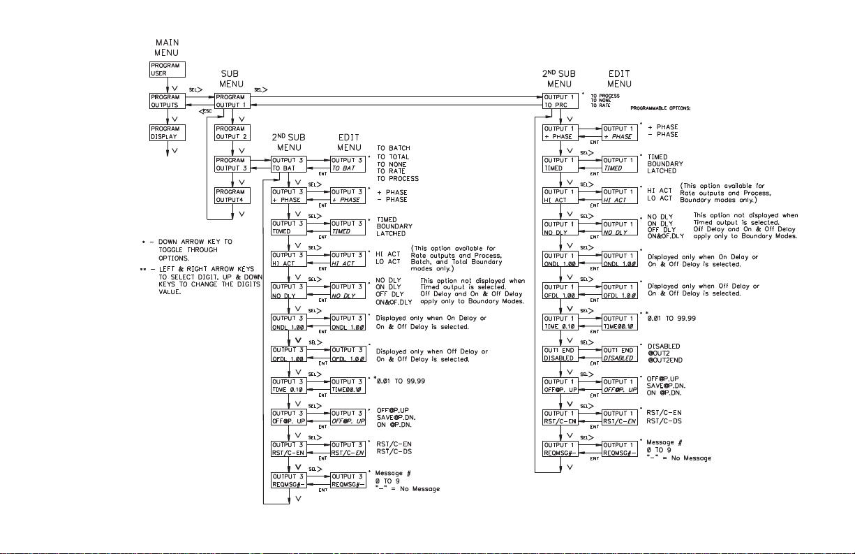
PROGRAM OUTPUTS MODULE
Presets 1 and 2 can activate relay Outputs 1 and 2 respectively. They can be
assigned to the Process Count, Rate Indication display, or None. Output 2 has
the same programmable options as Output 1. Presets 3 and 4 can activate solid
state Outputs 3 and 4 respectively. Outputs 3 & 4 can be assigned to the Batch
Count, Total Count, Process Count, Rate indication display, or None. The
preset values are automatically assigned to the appropriate display. Outputs 3
and 4 have the same programmableoptions as Output 1, except they do not have
the Out End Mode option. Boundary mode is not available when the output is
assigned to the Batch counter. A manual reset, which requires the use of a User
Input, overrides a timed output. If boundaryor latched is selected for theoutput
mode the time value does not appear as an option. The flowchart on the
following page shows only the Outputs portion:
PHASE
The positive (+) phase of an output indicates that when the display value
equals the preset value, the output turns on. When the output is reset it is turned
off. The negative (-) phase of an output indicates that when the display value
equals the preset value, the output turns off. The reset condition of the output is
the on state. When an output phase is changed, it does not take effect until a
manual reset or power down is performed.
Note: The state of the relay, if used, is the same as the solid state output.
OUTPUT MODES - TIMED, LATCHED OR BOUNDARY
TIMED
For timed output operation, when the display value equalsthepreset value, the
output activates for the time selected. After the time value expires, the output
returns to its inactive state. The output time can be programmed from 0.01 to
99.99 seconds. An output may appear to be latched if thetimedelayislongerthan
the time required for the counter to reach the preset value. When an output is
assigned to the rate display, the output appears to be latched, if the output time
delay is greater than the minimum update time. The output deactivates when the
rate drops below the preset value and the output time expires.
LATCHED
An output selected for the Latched Mode activates when the display value
equals the preset value. The output stays active until it is manually reset by a User
Input selected for that function. When the unit is reset, the output returns to its
inactive state.
BOUNDARY
An output selected for the Boundary mode (Hi Acting) is active when the
display value is greater than or equal to the positive preset value. If the display
value is less than the positive preset value, the output will be inactive. For
negative preset values, the output will be active when the count value is less
(more negative) than the negative preset value. The output will be inactive when
the display value is greater (more positive) or equal to the negative preset value.
If outputs 1 or 2 are programmedfor boundary,the Output End (Reset) Modes are
not applicable and therefore do not appear in the display.
HI/LO ACTING
This mode is used inconjunction with all Rate modes, and also with Boundary
count modes. A Lo acting output would perform the Output action when the
count/rate is lower than the preset. A Hi acting output would perform the Output
action when the count/rate is higher than or equal to the preset.
RATE OUTPUT ON/OFF DELAY
This option is available for the rate indicator and is used to prevent output
chatter. The output condition mustbe satisfied for a period of time longer than the
delay period for the output state to change. The minimum on or off delay time
allowed is 0.10 seconds.ON/OFF Delay is not available if output is set for TIMED
operation. If LATCHED mode is selected, the OFF DLY options are not available.
NO DLY - No delay
ON DLY. - On Delay:
Prevents activation of output(s) for the amount of time
programmed.
OFF DLY. -OffDelay:
Prevents deactivation of output(s) for the amount of time
programmed.
OF&ON.DLY - On & Off Delay:
This mode prevents output state change for specified delay period
when turning on or off.
-25-
Page 28
-26-
Page 29

OUTPUT END (RESET) MODES - OUT1 END, OUT2 END
The Output End modes operate with a timed or latched output mode. If either
output is selected asboundary, the Output End modes areNOT available. Output
End Modes apply only to outputs 1 and2when assigned to the Process counter. If
the output is set for TIMED, the output mayde-activate from timing out or when
the output end mode is reached, whichever occurs first.
OUT1 END (OUTPUT 1)
@OUT2 (Output 1 End at Output 2 Start)
Output 1 resets to its inactive state when output 2 becomes active. This
action occurs when the count equals the presetvalue or zero (Reset to
Preset Modes). This mode does not apply if the output is activatedbya
User Input programmed for Set Output.
@OUT2END (Output 1 End at Timed Output 2 End)
Output 1 resets to its inactive state when output 2’s time delay expires.
OUT2 END (OUTPUT 2)
@ OUT1 (Output 2 End at Output 1 Start)
Output 2 resets to its inactive state when output 1 becomes active. This
action occurs when the count equals the presetvalue or zero (Reset to
Preset Modes). This mode does not apply if the output is activatedbya
User Input programmed for Set Output.
@OUT1END (Output 2 End at Timed Output 1 End)
Output 2 resets to its inactive state when output 1’s time delay expires.
OUTPUT POWER UP STATE (OFF@P.UP, SAVE@P.DN OR ON
@P.UP)
Each output can be programmed individually to have the state of the output
OFF at power up (OFF@P.UP), saved at power down (SAVE@P.DN) or ON at
power up (ON @P.UP). The save at power down option restores the state of the
output to what it was at power down when power is restored. The save at power
down option DOES NOT restore a timed output to the active state if the output
was active at power down. The OFF@P.UP and ON @P.UP option refers to the
active state of the output, which is determined by the Output Phase.
RESET OUTPUT WITH COUNT (RST/C-EN OR DS)
If Reset with Count is enabled, the output resets with a manual reset of the
Process, Batch, Total orRate display. If Resetwith Count is Disabled,the output
does NOT reset when a manual reset is performed on the value to which the
output is assigned.
REQUEST MESSAGE (REQMSG#—)
The selected messageis requested when the output is activated. This may be a
maintained or momentary request, as selected in the Program Message Module.
A dash ‘-’ indicatesthat no message is to be requested. The outputmust be active
for a minimum of 5 0 msec for the request to be seen.
-27-
Page 30

PROGRAM DISPLAY MODULE
DISPLAYS 1 TO 4
The four indication displays are programmed individually. Each line of each
display can be configured to show avaluemnemonic,anumericvalue,the output
status, a preset value, the counter load value, or a custom display line. Each
display can be programmed to be Green or Red on Dual Color models. The full
value mnemonics are factory set to:
RATE
PEAK
VALLEY
PROCESS
BATCH
TOTAL
The first character of the full mnem onicis displayed to the left of the appropriate
numeric value if the other line is not programme dto display the full mnemonic. The
mnemonic for the Total is not shown in the display, since the total count requires
eight digits. For rate peak and rate valley displays, the abbreviated mnemonic is the
first character of the full rate mnemonic, followed by the first character of the full
peak or valley mnemonic. The following is a list of the single or dual character
mnemonics that are displayed for the factory set full mnemonics:
R - Indicates the Rate Value.
Rp - Indicates the Rate Peak Value.
Rv - Indicates the Rate Valley Value.
P - Indicates the Process Counter Value.
B - Indicates the Batch Counter Value.
O -1234 - Indicates output status:
P1 - Indicates Preset 1 Value.
P2 - Indicates Preset 2 Value.
P3 - Indicates Preset 3 Value.
P4 - Indicates Preset 4 Value.
CL - Indicates Counter Load Value.
The numeric digits show which outputs are on.
When the output is off, the digit is replaced by a small box (
n).
SCROLL SPEED (SCRO.SPD)
The indication displays can be set to scroll automatically at a 2.5 or 5 second
rate. The displays can be selected not to scroll, in which case the up and down
arrow keys are used to scroll through the disp lays.
DISPLAY INTENSITY (DSP.LEVEL)
The brightness of the backlighting can be adjusted from 1 to 5, with 5 as the
brightest. On dual color models, there is a separate adjustment for each color.
CUSTOM DISPLAY LINES (CUST.DSP.1 / CUST.DSP.2)
The Legend Plus has two Custom Display Lines which allow the user to specify
the number of digits of a value to be displayed on the line, along with any
alpha-numeric prefix or suffix. This feature has the same available characters as
messages and program mnemonics. The numeric digit positions are indicated by
pressing F1 and ENT atthe desired display position. For acompletelist of characters
and text editing key functions, see Program Messages Text Editing section.
MNEMONIC
Allows the user to modify main display values (RATE, PROCESS, BATCH,
etc.) to display the value of their choice. For example, the value “ RATE” can be
changed to read “SPEED”. See Program Messages Text Editing section for a
complete listing of available characters and text editing commands.
-28-
Page 31

The following flowchart shows only the Display portion:
-29-
Page 32

PROGRAM MESSAGE MODULE
Up to 10 messages can beprogrammed in the LegendPlus.Messages
can be requested by an output status change, User Input(s), or through
serial communications. The messages can be programmed for block or
character scrolling, to blink, time out, and to alternately flash between
message and indication display. On dual color models the message can
be programmed to be displayed in the other color. This would by useful
in drawing the operator’s attention to the message. The following
flowchart shows only the Message portion:
MESSAGE TYPE
1L Block - A 1 line block message utilizes the top line of the display.
The bottom line of the display indicates the information that was
viewed before displaying the message. When there are multiple
blocks in a message, the message text sequences to the next block
every 2 seconds.
2L Block - A 2 line block message uses both lines of the display to
display the message. Messages with more than 1 block
automatically sequence to the next block every 2 seconds.
1L Scrol - The message text scrolls f rom left to right on the top line of
the display. The bottom line of the display indicates theinformation
that was viewed before displaying the message. The scroll rate is
approximately 3 characters per second.
2L Scrol - The message text scrolls f rom left to right on the top line of
the indication display. The bottom line of the display is blanked.
When the message type is changed, the unit automatically replaces
End of Blo ck or End of Line Characters with End of Line or space
characters if appropriate. The message text may require editing when
the message type is changed.
-30-
Page 33

MESSAGE TEXT
A message can contain up to 200 characters. The keypad can be used to perform
message editing functions such as; scrolling through message text, inserting and
deleting characters, toggling from upper/lower case, toggling from
Extended/Standard ASCII characters sets, etc. Refer to table below for text editing
key functions. Message Text and other message parameters may also be
programmed utilizing the optional Legend Plus Programming Software.
Before entering message text, the message type (1L/2L Block or Scroll) should
be configured. This selection will affect the formatting of the message text. When
entering block messages, an end ofline character and an end ofblock character can
be used to conserve message memory. The End of Line character is displayed as a
small open square. It is used onlyon the top line in 2line block messages. If there is
more than one space at the end of the top line, the End of Line character should be
inserted after thelast non space character. The End ofBlock character is displayed
as a large open block. It can be inserted after the last character of a message block
on either displayline. Message blocks that contain only End of Line and/or End of
Block characters will be blank when displayed. The End of Line or End of Block
are not used in character scrolling messages (1L or 2L Scrol).
The Last character in a message is the End of Message character, which is
displayed as a large solid block. The End of Message character cannot be edited.
Text Editing Key Functions:
Scroll through characters
Select Character position
Reset to “A” character
Reset to the space character
Insert space Character, push right
Delete character, pull left
Insert End of Line 1 Character
Insert End of Block Character or
Numeric Field Position (Custom Disp. lines)
Upper/Lower Case toggle
Toggle between Extended & Standard Character
Keys Pushed
or v
^
>or<
F1 +
^
F1 + v
F1 + >
F1 + <
F1 + PRS
F1 + ENT
F2 +
^
F2 + v
SPECIAL USE CHARACTERS
n - End of Line 1
[] - End of Block
z - End of Message (Non editable)
Note: In message and mnemonic text entry, the F1 & F2 User Input functions are
disabled.
ASCII TABLE OF STANDARD CHARACTERS
HEXA
DECIMAL
DECIMAL
80 128 Ç
81 129 ü
82 130 é
83 131 â
84 132 ä
85 133 à
86 134 å
87 135 ç
88 136 ê
89 137 ë
8A 138 è
8B 139 ï
8C 140 î
8D 141 ì
8E 142 Ä
8F 143 Å
90 144 É
91 145 æ
92 146 Æ
93 147 ô
94 148 ö
LEGEND
CHARACTER
HEXA
DECIMAL
DECIMAL
95 149 ò
96 150 û
97 151 ù
98 152 ÿ
99 153 Ö
9A 154 Ü
9B 155 ¢
9C 156 £
9D 157 ¥
9E 158 Á
9F 159
A0 160 á
A1 161 í
A2 162 ó
A3 163 ú
A4 164 ñ
A5 165 Ñ
A6 166 Ó
A7 167 Ú
A8 168 ¿
LEGEND
CHARACTER
Í
-31-
Page 34

PROGRAM MESSAGE MODULE (Cont’d)
ASCII TABLE OF STANDARD CHARACTERS
HEXA
DECIMAL
DECIMAL
20 32
21 33 !
22 34 "
23 35 #
24 36 $
25 37 %
26 38 &
27 39 ’
28 40 (
29 41 )
2A 42
2B 43 +
2C 44 ,
2D 45 2E 46 .
2F 47 /
30 48 0
31 49 1
32 50 2
33 51 3
34 52 4
35 53 5
36 54 6
37 55 7
LEGEND
CHARACTER
*
HEXA
DECIMAL
DECIMAL
38 56 8
39 57 9
3A 58 :
3B 59 ;
3C 60 <
3D 61 =
3E 62 >
3F 63 ?
40 64 @
41 65 A
42 66 B
43 67 C
44 68 D
45 69 E
46 70 F
47 71 G
48 72 H
49 73 I
4A 74 J
4B 75 K
4C 76 L
4D 77 M
4E 78 N
4F 79 O
LEGEND
CHARACTER
HEXA
DECIMAL
DECIMAL
50 80 P
51 81 Q
52 82 R
53 83 S
54 84 T
55 85 U
56 86 V
57 87 W
58 88 X
59 89 Y
5A 90 Z
5B 91 [
5C 92 \
5D 93 ]
5E 94 ^
5F 95 _
60 96 ‘
61 97 a
62 98 b
63 99 c
64 100 d
65 101 e
66 102 f
67 103 g
LEGEND
CHARACTER
HEXA
DECIMAL DECIMAL
68 104 h
69 105 I
6A 106 j
6B 107 k
6C 108 l
6D 109 m
6E 110 n
6F 111 o
70 112 p
71 113 q
72 114 r
73 115 s
74 116 t
75 117 u
76 118 v
77 119 w
78 120 x
79 121 y
7A 122 z
7B 123 {
7C 124 |
7D 125 }
7E 126 ~
LEGEND
CHARACTER
-32-
Page 35

MESSAGE PRIORITY (PRIOR - 1)
Messages can be assigned a priority from 1 to 8 (1 = highest priority).
Messages of equal or higher priority will supersede or replace a displayed
message of lower or equal priority.
BLINKING MESSAGE (BLNK-YES/NO)
This parameter enables the message to blink at a one second rate when
displayed. This mode is only available with 1 or 2 line block messages.
MULTIPLEX (MUX - YES/NO)
Allows a message to be multiplexed with the indication display. The unit
displays the requested message then the indication display each for 2 seconds.
Message multiplexing is only available with 1 or 2 line block messages.
MAINTAINED/MOMENTARY MESSAGE REQUEST
Maintained Request (MNT. REQ)
Programming a message for maintained request allows the message to be
re-requested if the message has been displaced by another message. To be
re-requested, the User Input or output requesting the message must be active
(maintained) and the interrupting message must have been cancelled.
Maintained messages of the same priority are treated as follows when more
than one message requesting input or output is active. A new messageof thesame
or higher priority will always be requested when the request source is activated.
When a maintained message is cancelled, the message of the requesting input or
output of highest priorityisdisplayed. The priority order, from highest to lowest,
for the various request sources are:UserInput 1, 2, 3, 4, UserF1,User F2, Binary
Message Request inputs, and Outputs 1 to 4. User Input 1 (programmed for
REQ.MSG) has the highest priority and Output 4 has the lowest.
Momentary Request (MOM. REQ)
Once a momentary message is displayed, if another message is requested and
displaces the momentary message, the momentary message is cancelled.It will not
be requested again unless the User Input or output is deactivated then activated
again. If no other messages are requested while the momentary message is
displayed, it remains on the display until cancelled as programmed.
MESSAGE CANCELLATION
Any displayed message is immediately displaced when another message of
equal or higher priority is requested. A displayed message can also be cancelled
by activating a User Input programmed for the Cancel Message function, or via
the serial port. If no other function purposely cancels a message, it is cancelled
per the cancellation mode programmed. A message that is programmed for
maintained request will be re-requested when the message times out or is
cancelled, if the request source (User Input or output) is still active. If several
maintained messages’ request sources are active, and the last requested message
times out or is cancelled, the message associated with the highest priority input
will be requested next (See Maintained Request).
LATCHED - Latched messages can only be cancelled by the methods
described above.
TIMED - Timed messages automatically cancel at the end of the specified time
period as programmed in “MESSAGE TIME”. A Characteror block scrolling
message will scroll to theend before being cancelled. Thiscauses the message
to remain on the display longer than specified by the time-out value. A 2 Line
Block message will stay on the display for a minimum of 2 sec. (1 block time)
before timing out. The messagetimeoutvalueisinitiallyset to 5 seconds when
the timed mode is selected.
TIL END - A message programmed for this mode will automatically get
cancelled when the output orUser Input programmed to request this particular
message deactivates. Only one request source should be programmed to
request a message set for Til End. A TilEndmessagethatis requested by serial
communication will be immediately cancelled, if there is an inactive request
source set to request that message.
MESSAGE TIME
This parameter is available onlyif the message cancellation modeis set for timed.
The messagetimeforatimedmessagecanbeprogramm edfrom 1 to 599 seconds.
MESSAGE COLOR
Can be programmed for Red or Green on dual color models.
-33-
Page 36

PROGRAM COMMUNICATION PORT
When communicating to a Legend Plus via the serial port, the data formats of
both units must be identical. The Baud Rate and Parity Bit/number of d ata bitsare
selected for the data format in thismodulealong with the Unit Address and Serial
Transmit Delay. Serial communication is covered in detail in the SERIAL
COMMUNICATIONS SECTION. The following flowchart shows only the
Communication portion:
BAUD RATE
The Baud Rates available are: 1200, 2400, 4800, and 9600 Baud.
UNIT ADDRESS
The Unit Address can range from 00 to 99. This allows addressing ofmultiple
units on a single pair of wires and a common (RS-485 only), with each unit
capable of having a different address. If only one unit is on the line an address of
zero can be used, eliminating the need for an address command.
SERIAL TRANSMIT DELAY
The Serial Transmit Delay is the minimum amount of time the Legend Plus
unit waits to transmit data to a peripheral unit. The time begins after the Legend
Plus receives a command to transmitdataor when a print requestis received. The
delay can be set for 0.002 or 0.100 second. This delay time gives the software
controlling an RS-485 interface card time to change the RS-485 port from
transmit to receive mode.
PARITY/ NUMBER OF DATA BITS
The Parity can be ODD-7B (7data bits),EVEN-7B(7 data bits), or No parity-8B
(8 data bits). If any of the extended ASCII characters are to be transmitted serially
(used in mnemonics, custom display line, or in message #0 when MSG0-YES is
configured), the unit must be configured for 8 data bits (NONE - 8B).
-34-
Page 37

PROGRAM PRINT OPTIONS MODULE
A print operation occurs when a User Input, programmed for the print request
function, is activated or when a “P” command is sent via the serial communications
port. The unit will transmit the values selected as “YES” in this module.
If a display is in an overflow condition, an asterisk will precede the digits that
are printed (ex. positive overflow * 2178, negative overflow * -2178).
Serial transmissions are covered in detail in the serial communications section.
MNEMONICS (MNEM-YES/NO)
When transmitting data, the unit can be programmed to suppress the address
number, mnemonics, and some spaces by selecting NO for the MNEM
(mnemonics). A selection of NO results in a faster transmission and may be useful
when interfacing with a computer. However, when interfacing with a printer,
sending mnemonics is usually desirable. Setting MNEM to YES inserts the address,
mnemonicsand a 400 msec printer delay following each transmittedprintoption.An
example of sending and NOT sending mnemonics are shown below:
6 PRC 123.8<CR><LF> with mnemonics
123.8<CR><LF> without mnemonics
TRANSMIT AND RESET (TX&R-YES/NO)
When programmed to YES all count values selected to be printed are reset
after the count value is acquired for serial transmission.
MESSAGE 0 (MSG0-YES/NO)
Enables the first 60 characters of message #0 to be transmitted as a print header
(first item in the print out). For a single line print header,programmessage#0 as1L
or 2L Scroll. For a multiple line print header, program message #0 as 1L or 2L
Block. The End of Line or End of Block character is used to indicate the end of a
line of header.Do not use themin the same fashion as messages to bedisplayed on
the unit. When entering the text for each line,ifaworddoes not fit on a line, allow it
to continue on the next line or block. Refer to Program Messages section.
The following flowchart shows only the Print Options portion:
-35-
Page 38

PROGRAM OPTIONS MODULE
The Program Options module is used to program the Operator Accessible
functions, Preset Tracking selections, the Programmable Code value,or load the
Factory Settings. The following flowchart shows only the Options portion:
OPERATOR ACCESS
The Operator Access menu is used with the Program Disable DIP switch
and/or an external User Input selected for program disable. Values can be set for
YES, NO, or LOC. When a value is selected for NO, the operator can view the
value, but CANNOT change it from the front panel keypad (See Front Panel
Accessible Functions With Program Disable for details). Values selected for
LOC do not appear in the displays outside of the programming loop. The
following values can be disabled from front panel access programming:
Preset 1 Preset 4
Preset 2 Counter Load value
Preset 3 Scale Factors
PRESET TRACKING
If Preset Tracking is enabled and a preset valueis changed, the preset value that
is tracking it will also change by the same offset. The amount of offset between
presets is changed by changing the preset value doing the tracking first. Example:
Preset 1 is tracking Preset 2. If Preset 2 is 100 and it is desired that Preset 1 occurs
20 counts before Preset 2, the Preset 1 value would be set to 80. If Preset 2 is then
changed to 200, Preset 1 will automatically change to 180, maintaining the same 20
count Offset. All presets can be set to track a different preset if they are assigned to
the same function (rate, total, process, etc). If only one preset is selected for a
particular function then that preset cannot be used for preset tracking.
PROGRAM CODE (PRO. CODE)
The value can be programmed from 0 to 99. This value may be required to be
entered before the unit allows access to programming menus, depending on the
level of security that has beenchosen. Programmingavalue of 99 disables access
to programming menus when PGM.DIS. switch is on. Refer to “Front Panel
Accessible Functions with Program Disable.”
-36-
Page 39

USER SETTINGS
This module should only beentered if the operator wantsto reset ALL parameters
to the factory settings. When the word “FACTORY” is flashing in the display and the
ENT key is pressed,all parameters will be set to the factory settingswhen exiting the
LGPB FACTORY SETTINGS PROGRAM SHEET
programming loop. The operator can exit the factory settings option WITHOUT
resetting all parameters by pressing the <ESC key. The following are the settings
when shipped from the factory, along with a chart for user settings:
Caution: If factory settings are selected, all programming by the user will be reset.
SCALE FACTORS
COUNT SF 1.0000
RATE SF 1.0000
TOT SF 1.0000
CNT. SCM X 1
CNT. D.P. 0
RATE SCM X 1
RATE PER SECOND
RATE D.P. 0
TOT D.P. 0
CHG. CNT/
WITH SF YES
RATE
MIN. TIME 1.0
MAX. TIME 5.0
COUNTER
CNT. INPUT CT+DIRX1
PRC. RST. TO ZERO
P AUTO. RS DISABLED
BAT. RST. TO ZERO
B AUTO. RS DISABLED
TOT. RST. TO ZERO
USER INPUTS
BIN. MSG.REQ. NONE
USER INP. 1 NO MODE
USER INP. 2 NO MODE
USER INP. 3 NO MODE
USER INP. 4 INHIBIT
USER F1 MNT RST
USER F2 MNT RST
RATE-NO
PEAK-YES
VALLEY-YES
PROCESS-NO
BATCH-NO
TOTAL-NO
RATE-NO
PEAK-NO
VALLEY-NO
PROCESS-YES
BATCH-YES
TOTAL-YES
-37-
OUTPUT 1
ASSIGNED TO PRC
PHASE +
TYPE TIMED
ACT/TIME 0.10
OUTPUT END DISABLED
DLY TYPE
ON DL TIME
OF DL TIME
OFF@P. UP
RST/C EN
REQ MSG #
OUTPUT 3
ASSIGNED TO BAT
PHASE +
TYPE TIMED
ACT/TIME 0.10
DLY TYPE
ON DL TIME
OF DL TIME
OFF@P. UP
RST/C EN
REQ MSG #
OUTPUTS
OUTPUT 2
ASSIGNED TO PRC
PHASE +
TYPE TIMED
ACT/TIME 0.10
OUTPUT END DISABLED
DLY TYPE
ON DL TIME
OF DL TIME
OFF@P. UP
RST/C EN
REQ MSG #
OUTPUT 4
ASSIGNED TO BAT
PHASE +
TYPE TIMED
ACT/TIME 0.10
DLY TYPE
ON DL TIME
OF DL TIME
OFF@P. UP
RST/C EN
REQ MSG #
Page 40

LGPB FACTORY SETTINGS PROGRAM SHEET (Cont’d)
DISPLY 1
D1 LINE 1 CUST.DSP.2
D1 LINE 2 CUST.DSP.1
D1 COLOR GREEN
DISPLY 3
D3 LINE 1 VALI-MNE
D3 LINE 2 VALI-VAL
D3 COLOR GREEN
SCRO. SPD NONE
DSP. LEVEL G 5
CUST. DSP.
CUST. DSP.1 VAL-RATE
CUST. DSP.2 VAL-PRC
R5
CPS
PRC
MSG. # 0 to 9
TYPE 1L BLOCK
TEXT S
PRIORITY 1
BLINKING NO
MULTIPLEX NO
MOM/MNT REQ MNT
CANCEL LATCHED
TIME SEC.
COLOR GREEN
S - Message Number (single digit) is
entered in message text.
DISPLAY
MESSAGE
DISPLY 2
D2 LINE 1 PEAK-MNE
D2 LINE 2 PEAK-VAL
D2 COLOR GREEN
DISPLY 4
D4 LINE 1 PRC-MNE
D4 LINE 2 PRC-VAL
D4 COLOR GREEN
MNEMONIC
RATE RATE
PEAK PEAK
VALLEY VALLEY
PROCESS PROCESS
BATCH BATCH
TOTAL TOTAL
OVERFLOW OVERFLOW
MEM AVAIL 332
COM. PORT
BAUD RATE 9600
PARITY ODD-7B
ADDRESS 00
XMIT DLY 0.100
PRINT OP
RATE YES
PEAK NO
VALI NO
PRC YES
BAT YES
TOT YES
SF’S NO
P1&2 NO
P3&4 NO
CTLD. NO
MNEM YES
TX&R NO
MSG0 NO
OPTIONS
ACCESS
P1 YES
P2 YES
P3 YES
P4 YES
CTLD. YES
SF’S YES
PRESET TRACKING
P1 TRACK NONE
P2 TRACK NONE
P3 TRACK NONE
P4 TRACK NONE
PRO. CODE 0
PRESETS
P1 500
P2 1000
P3 300
P4 400
CL -100
-38-
Page 41

LGPB USER SETTINGS PROGRAM SHEET
SCALE FACTORS
COUNT SF
RATE SF
TOT SF
CNT. SCM
CNT. D.P.
RATE SCM
RATE PER
RATE D.P.
TOT D.P.
CHG. CNT/
WITH SF
BIN. MSG.REQ.
USER INP. 1
USER INP. 2
USER F1
USER INPUTS
MIN. TIME
MAX. TIME
CNT. INPUT
PRC. RST.
P AUTO. RS
BAT. RST.
B AUTO. RS
TOT. RST.
USER INP. 3
USER INP. 4
USER F2
RATE
COUNTER
OUTPUT 1
ASSIGNED
PHASE
TYPE
ACT/TIME
OUTPUT END
DLY TYPE
ON DL TIME
OF DL TIME
@P.
RST/C
REQ MSG #
OUTPUT 3
ASSIGNED
PHASE
TYPE
ACT/TIME
DLY TYPE
ON DL TIME
OF DL TIME
@P.
RST/C
REQ MSG #
OUTPUTS
OUTPUT 2
ASSIGNED
PHASE
TYPE
ACT/TIME
OUTPUT END
DLY TYPE
ON DL TIME
OF DL TIME
@P.
RST/C
REQ MSG #
OUTPUT 4
ASSIGNED
PHASE
TYPE
ACT/TIME
DLY TYPE
ON DL TIME
OF DL TIME
@P.
RST/C
REQ MSG #
-39-
Page 42

DISPLY 1
D1 LINE 1
D1 LINE 2
D1 COLOR
DISPLY 3
D3 LINE 1
D3 LINE 2
D3 COLOR
SCRO. SPD
DSP. LEVEL G
CUST. DSP.
CUST. DSP.1
CUST. DSP.2
LGPB USER SETTINGS PROGRAM SHEET (Cont’d)
DISPLAY
DISPLY 2
D2 LINE 1
D2 LINE 2
D2 COLOR
DISPLY 4
D4 LINE 1
D4 LINE 2
D4 COLOR
MNEMONIC
R
RATE
PEAK
VALLEY
PROCESS
BATCH
TOTAL
OVERFLOW
MEM AVAIL
MSG. #
TYPE
TEXT
PRIORITY
BLINKING
MULTIPLEX
MOM/MNT REQ
TIMED
TIME SEC.
COLOR
MSG. #
TYPE
TEXT
MESSAGE
MSG. #
TYPE
TEXT
PRIORITY
BLINKING
MULTIPLEX
MOM/MNT REQ
TIMED
TIME SEC.
COLOR
MSG. #
TYPE
TEXT
MSG. #
TYPE
TEXT
PRIORITY
BLINKING
MULTIPLEX
MOM/MNT REQ
TIMED
TIME SEC.
COLOR
MESSAGE
MSG. #
TYPE
TEXT
PRIORITY
BLINKING
MULTIPLEX
MOM/MNT REQ
TIMED
TIME SEC.
COLOR
-40-
PRIORITY
BLINKING
MULTIPLEX
MOM/MNT REQ
TIMED
TIME SEC.
COLOR
PRIORITY
BLINKING
MULTIPLEX
MOM/MNT REQ
TIMED
TIME SEC.
COLOR
Page 43

MSG. #
TYPE
TEXT
PRIORITY
BLINKING
MULTIPLEX
MOM/MNT REQ
TIMED
TIME SEC.
COLOR
MSG. #
TYPE
TEXT
PRIORITY
BLINKING
MULTIPLEX
MOM/MNT REQ
TIMED
TIME SEC.
COLOR
MESSAGE
MSG. #
TYPE
TEXT
PRIORITY
BLINKING
MULTIPLEX
MOM/MNT REQ
TIMED
TIME SEC.
COLOR
MSG. #
TYPE
TEXT
PRIORITY
BLINKING
MULTIPLEX
MOM/MNT REQ
TIMED
TIME SEC.
COLOR
BAUD RATE
PARITY
ADDRESS
XMIT DLY
RATE
PEAK
VALI
PRC
BAT
TOT
SF’S
P1&2
P3&4
CTLD.
MNEM
TX&R
MSG0
COM. PORT
PRINT OP
ACCESS
P1
P2
P3
P4
CTLD.
SF’S
PRESET TRACKING
P1 TRACK
P2 TRACK
P3 TRACK
P4 TRACK
PRO. CODE
P1
P2
P3
P4
CL
OPTIONS
PRESETS
-41-
Page 44

SERIAL COMMUNICATIONS
Serial communications allows for transmitting and receiving of data between
the Legend Plus and other devices. This feature can be used for monitoring
various values, resetting output(s), and changing values, all from a remote
location. Typical devices that are connected to a Legend Plus unit are a printer, a
terminal, a programmable controller, or a host computer.
The Legend Plus is jumper selectable between RS-485 and RS-232
communications. The RS-485 differential (balanced) design has good noise
immunity and allows for communication distances of up to 4000 feet. Up to 32
units can be connected on a pair of wires and a common. The unit’s address can
be programmed from 00 to 99. RS232 is useful for connecting a single unit to a
printer or to a computer for programming using the optional Legend Plus
Programming Software.
PROGRAMMING SOFTWARE
Software for IBM compatible PCs is available to program all of the Legend
configuration parameters such as messages, count modes, etc. The software allows
unit configurations to be created, uploaded,downloaded,and saved to a file for rapid
programming of the Legend. Before using the programming software, the Legend
unit should be powered up and the version number recorded. This information is
needed to take full advantage of the programming software capabilities.
Note: While using the Legend Plus Programming Software, the Legend unit
should NOT be controlling a p rocess. If the unit is connected while uploading
or downloading the configuration files, unit operation will be interrupted and
counts will be missed.
MINIMUM REQUIREMENTS:
®
IBM
compatible 286 or better.
Minimum of 450K FREE conventional memory.
MSDOS 3.3 or later.
RS-232 or RS-485 serial port with ID of COM1 or COM2.
Video TEXT mode of 80 columns x 25 rows.
Mouse supported.
INSTALLING SOFTWARE
A backup copy should be made of the program disk. The program may be run
using the floppy drive or, it may be installed to a Hard drive. To install on the hard
drive, copy all files from the programdiskto the desired directory on the hard drive.
Refer to “SERIAL CONNECTIONS” section of the manual for connecting
the Legend Plus to a computer.
USING SOFTWARE
To start the Legend Programming Software (SFLGP) switch to the
disk/directory that contains the Software. Type SFLGP and press ENTER. The
software will display an opening screen that displays the current version of the
Legend Programming Software. Press ENTER to proceed to the main editing
screen. The screen is divided into four areas. The top of the screen contains a
pull-down menu that allows actions suchas uploading and downloading of afile.
The bottom of the screen displays an alternate method of accessing thepull-down
menu selections by using the F1-F8 keys in combination with the ALT key. The
middle section displays the programming parameters of the current file and
model of Legend. Below the pull-down menu is the file status info rmation that
indicates the currentfilename, model and availablemessage/mnemonicmemory
available. Multiple pages are used to display all of the programming parameters.
To change the page displayed press PGUP/PGDN or use the mouse to click on
the arrows located at the upper and lower right of the screen.
Uploading/Downloading of files from the Legend requires that the Baud Rate
and Unit Address of both the Legend and the SFLGP be identical. Prior to
performing either an upload or download, a menu of the current PC
communications settings will be displayed. These settings may be modified
before proceeding with the intended action. Once the action is started, the
Legend will display “TX’ING PROGRAM” if uploading or “RX’ING
PROGRAM” if downloading. Uploading is file transfer from the LEGEND to
the PC and Downloading is file transf er from the PC to the Legend.
-42-
Page 45
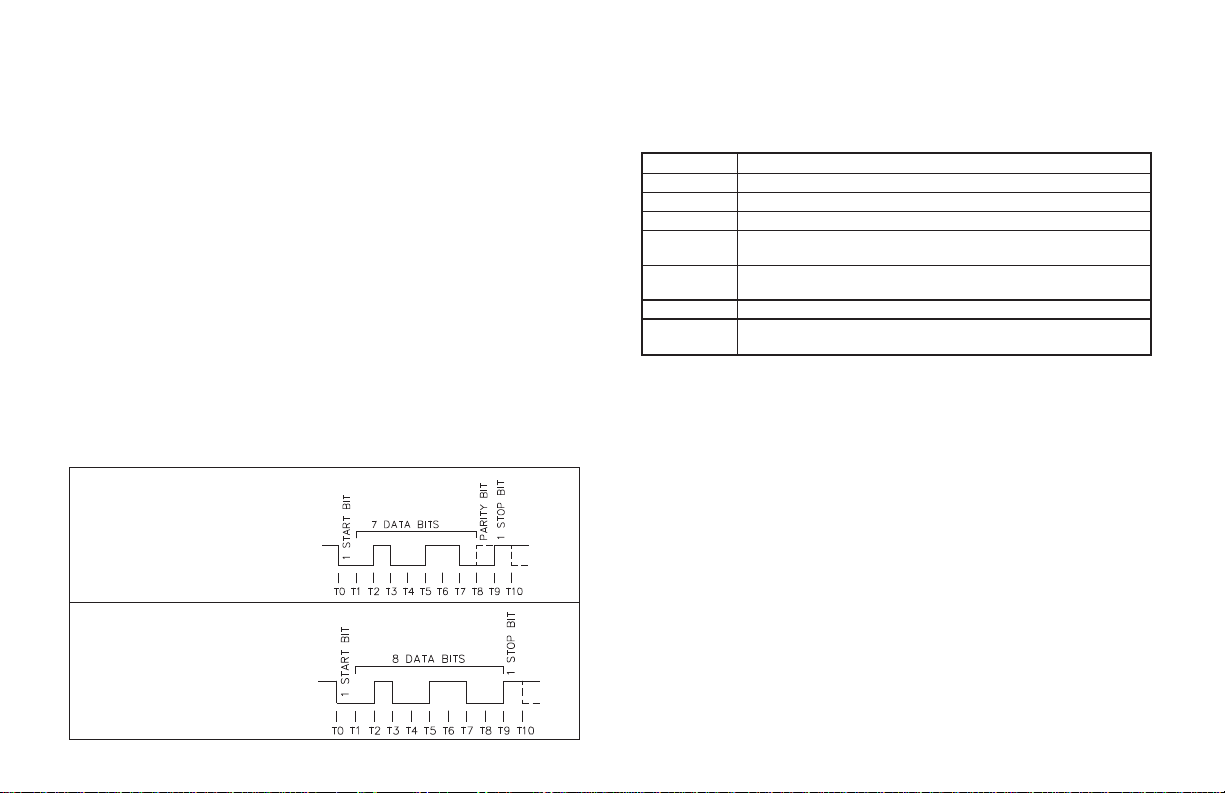
COMMUNICATION FORMAT
The half-duplex communication operation sends data by switching voltage
levels on the common pair of wires. Data is received by monitoring the levels and
interpreting the codes that were transmitted. After the Legend Plus receives a
Transmit Command or Print Request, it waits the Serial Transmit Delay time
before it begins transmitting data.The serial transmit delay can be programmedfor
0.002 or 0.100 second. For data to be interpreted correctly, there must be identical
formats and baud rates betweenthe communicatingdevices. The formats available
for the Legend Plus unit are 1 start bit, 7 or 8 data bits, No parity or 1 parity bit(odd
or even) and 1 stop bit. The available baud rates are; 1200, 2400, 4800, or 9600
baud. If any extended characters are to be used or transmitted, the Legend Plus
communication port should be set-up for Parity of “NONE-8B”. This configures
the unit to accept and transmit 8 data bits with no parity.
Before serial communication can take place,theunit must be programmed to
the same baud rate and parity asthe connected equipment. In addition, the loop
address number and printoptions should be known. When used witha terminal
or host computer andonly one unit is employed, an address of zero (00) may be
used to eliminate the requirement for the address specifier when sending a
command. If more than one unit is on the line, assignment of unique non-zero
addresses is required.
DATA FORMAT
10 BIT FRAME
[Parity = ODD-7B, EVEN-7B]
DATA FORMAT
10 BIT FRAME
[Parity = NONE-8B]
SENDING COMMANDS AND DATA
When sending commands to the Legend Plus unit, a command string must be
constructed. The command string may consist of command codes, value
identifiers, and numerical data. Belowis a list of commandsandvalue identifiers
that are used when communicating with the LGPB unit.
COMMAND DESCRIPTION
M (4DH)
MC (4DH, 43H)
N (4EH)
P (50H)
R (52H)
T (54H)
V (56H)
Request message command; Followed by the message number 0 to 9.
Clear message command.
Address command; Followed by the address number 1 to 99.
Transmit print options command; Transmits the options selected in the
Program Options Module section.
Reset value command; Followed by one Value Identifier (E, F, G, I, J, O, or
1 to 4 [for outputs]).
Transmit value command; Followed by one Value Identifier (A-O, or Q).
Change value command; Followed by one Value Identifier (A-G, K, L, O, or Q),
then the proper numerical data.
-43-
Page 46

SENDING COMMANDS AND DATA (Cont’d)
VALUE IDENTIFIERS MNEMONIC
A (41H) PRESET 1 P1
B (42H) PRESET 2 P2
C (43H) PROCESS SCALE FACTOR SFPS
D (44H) RATE SCALE FACTOR SFR S
E (45H) PROCESS PRO S
F (46H) BATCH BAT S
G (47H) TOTAL T S
H (48H) RATE RAT S
I (49H) PEAK PEA S
J (4AH) VALLEY VAL S
K (4BH) PRESET 3 P3
L (4CH) PRESET 4 P4
O (4FH) COUNTER LOAD CLD
Q (51H) TOTAL SCALE FACTOR SFT S
Note: Command identifiers other than those listed should NOT be transmitted.
Otherwise, undefined or unpredictable operation could result.
S From Factory Settings, the mnemonic transmitted is based on full mnemonic
programmed in Display Module. The print mnemonic is the first three
characters of the full mnemonic. The printed mnemonics for the Scale Factors
is SF followed by the first character of the full mnemonic for the value
associated with the Scale Factor.
The command string is constructed by using a command, a value identifier, and a
data value if required. The Data value need not contain the decimal point since it is
fixed within the Legend Plus unit, whenprogrammedat the front panel. The Legend
Plus will accept the decimal point, however, it does not interpret them in any way.
Leading zeros can be eliminated, but all trailing zeros must be present.
Example: If a Scale Factor of 1.0000 is to be sent, the data value can be
transmitted as 1.0000 or 10000.If a “1” istransmitted,the Scale Factor will be
changed to 0.0001.
The Address command is used to allow a command to be directed to a specific
unit on the Serial Communications Line. When the unit address is zero,
transmission of the Address command is not required. This is done for
applications that do notrequire more than one LegendPlus. For applications that
require several units, each Legend Plus on the line must be given a non-zero
address. If they are given the same address, a command such as the Transmit
Value Command,willcausealltheunits to respond simultaneously, resulting in a
communication collision. All Legend Plus units in a multiple unit application
should be given an address other than zero. If a unit has an addressof zero, it will
attempt to process any transmissions from the otherLegend Plus’s as commands.
These transmissions fill up the receive buffer of the unit with an address of zero,
which may produce unpredictable results.
The command string is constructed ina specific logical sequence. The Legend
Plus does not accept commandstrings that do notfollow this sequence. Onlyone
operation can be performed per command string. Below is the procedure to be
used when constructing a command string.
1. The first two or three characters of the command string must consist of the Address
Command (N) and the address number of the unit (1 to 99). If the Legend Plus
address is zero, the address comm and and number need NOT be sent.
2. The next character in the command string is the actual command that the
Legend Plus is to perform (M, MC, P, R, T, or V).
3. A Value or command Identifier is next if it pertains to the command. The
command P (print) does not require a Value Identifier.
4. The numerical data will be next in the command string if the “Change Value”
command is used.
-44-
Page 47

5. All command strings must be terminated with an asterisk S (2AH). This
character indicates to the Legend Plus that the command string is complete and
begins processing the commandBeloware some typical examples of properly
constructed command strings.
(EX. 1) Change Preset 1 Value to 123.4 on the Legend Plus with an
address of 2.
COMMAND STRING: N2VA1234
S
(EX. 2) Transmit the Process Count Value of the Legend Plus unit with
an address of 3.
COMMAND STRING: N3TE
S
(EX. 3) Reset Output 1 of the Legend Plus unit with an address of 0.
COMMAND STRING: R1
S
If illegal commands or characters are sent to the Legend Plus, the unit
addressed responds by transmitting an error character “E” (45H) in which case
the string must be re-transmitted.
When writing application programs in Basic, the transmission of spaces or
carriage return and line feed should beinhibited by using the semicolon delimiter
with the “PRINT” statement. The LegendPlus will not accept a carriage returnor
line feed as valid characters.
It is recommended that a “Transmit Value” command follow a “Change
Value” Command. If this is done, the reception of the data can provide a timing
reference for sending another command and ensures that the change has
occurred. When a “Change Value or Reset Value” command is sent to the Legend
Plus, time is required for the unit to process the command string. The diagrams
show the timing considerations that need to be made. The Legend Plus process
times shown are for a Legend Plus operating at the maximum count rate. The
process times are count rate dependent and will be considerably less when the
unit is operating at low count rates.
-45-
Page 48

RECEIVING DATA
Data is transmitted from the Legend Plus when a “T” TransmitValue or a “P”
Transmit Print Options command is sent to the Legend Plus via the serial port or
when a User Input, programmed for the Print Request function, is activated. The
Legend Plus will wait until the minimum serial transmit delay time (0.100 or
0.002 sec) expires and then begin transmissions. The Legend Plus can also be
programmedtotransmitMnemonics. The formatfor atypicaltransmissionstring
with mnemonics is shown below:
The first two digits transmitted are the unit address followed b y one blank
space. If the unit address is 0, the first locations are left blank. The next three
characters are the mnemonics followed by one or more blank spaces. The
numerical data value is transmitted next. Negative values are indicated by a “-”
sign. If the numeric value is in an Overflow condition, an asterisk (
precede the most significant d igit of the value. The decimal point position
“floats” within the data field depending on the actual v alue it represents. The
numeric data is right justified without leading zeros.
When a “T” command or print request is issued, the above character string is
sent for each line of a block transmission. An extra <SP><CR><LF> is
transmittedfollowing the last line of transmission from a print request, to provide
separation between print outs.
If Mnemonics are NOT transmitted (MNEM - NO print option), the Legend
only transmitsthe numericdata.Theunit address, extra spaces and 400 msec time
delay, is not sent. If the LegendPlus transmitsMnemonics(MNEM - YES), there
is a 400 msec built-in timedelay after each transmission string. When interfacing
to a printer, sending Mnemonics is usually desirable. Examples of transmissions
are shown below:
3 PRC -6732.5<CR><LF> (400 msec delay) Mnemonics Sent
-6732.5<CR><LF> NO Mnemonics Sent
S) will
The various Print Options are used with a printer or a Computer Terminal.
They provide a choice of which Legend Plus data values are to be printed, when
either the User Input,programmedfor the print request function is activated, or a
“P” (Transmit Print Options) command is sent to the Legend Plus via the serial
port. The Print Options are programmed in the “ProgramPrint Options” module,
the available options are:
A. Print Rate Value.
B. Print Peak Value.
C. Print Valley Value.
D. Print Process Count Value.
E. Print Batch Count Value.
F. Print Total Count Value.
G. Print Scale Factors (Count, Rate, & Total) Values.
H. Print Presets 1 & 2 Values.
I. Print Presets 3 & 4 Values.
J. Print Counter Load Value.
K. Print Mnemonics for all Values.
L. Reset selected Count values following print
M. Print Message 0.
A print out from a Legend Plus unit with an address of 1 and all print options
selected is shown below. Message #0 is programmed with the text, “MACHINE #1”.
MACHINE #1
1 RAT 54
1 PEA 100
1 VAL 0
1 PRO 4000
1 BAT 400
1 T 6000
1 SFP 1.0000
1 SFR 1.0000
1 SFT 1.0000
1 P1 500
1 P2 1000
1 P3 300
1 P4 400
1 CLD -100
-46-
Page 49

SERIAL CONNECTIONS
When wiring, remove the 12-position terminal block, which is on the top board
at the rear of the unit. Refer to the top label and configure the RS485/RS232
jumpers for the desired interface. Then, refertothenumberslisted on the label with
the terminal description for installing each wire in its proper location.
For RS-485 the data (transceiver) wires connect to the A (+)/TXD and B
(-)/RXD terminals. It is recommended that shielded (screened) cable be used f o r
serial communications. This unit meets the EMC specifications using Alpha
#2404 cable or equivalent. There are higher grades of shielded cable, such as,
four conductor twisted pair, that offer an even higher degree of noise immunity.
In some applications, a signal ground may be required to establish a ground
reference. The signal ground is required if the equipment does not have internal
bias resistors connected to the transceiver lines. The signal ground is connected
from only one LegendPlus to the equipment.If necessary, the shield can be used
as the signal ground.
TERMINAL DESCRIPTIONS
COMM. - Common required for some applications.
A (+)/TXD & B (-)/RXD - The Legend Plus transmits and receives on these
two terminals which are connected to the external device.
TX EN. - Used primarily with aRed Lion Controls (RLC) GCM422 moduleto
interface with an RLC model DMPC printer orconnect Legend Plus units in a 20
mA communication loop with other units.
For connection to a GCM232 Converter Module, refer to the diagram below.
For connection to an RS232 port on a computer, refer to diagrams below.
When all connections are made, replace the terminal block into its proper location.
-47-
Page 50

SERIAL CONNECTIONS (Cont’d)
CONNECTING TO A HOST TERMINAL
SixLegendPlusunitsareusedtomonitorand
control parts packaging machines in a plant. The
Legend Plus units are located at each machine in
the production area of the building. A
communication line is run to an Industrial
computer located in the production office. The
drawing shows the line connection. Each Legend
Plus is programmed for a different address and are
all programmed for the same baud rate and parity
as the computer (ex. 9600 baud, parity even). An
application program is written to send and receive
data from the units using the proper commands.
-48-
Page 51

TROUBLESHOOTING SERIAL COMMUNICATIONS
If problems are encountered when interfacing the Legend Plus(s) and host
devices or printers, the following check list can be used to help find a solution.
1. Check all wiring. Referto the previous application examplesanduse them as a
guide to check your serial communication wiring. Proper polarity of all
Legend Plus(s) and other peripherals must be observed.
2. Check RS232/RS485 configuration jumpers for proper interface selection.
3. If the Legend Plus is connected to a “host computer”, device or printer, check
to make sure that the computer or device is configured with the same
communication format as the Legend Plus. The communication format that
the Legend Plus will accept is; 1 start bit, 7 o r 8 data bits, no parity or 1 parity
bit (odd or even), and 1 stop bit.
4. Check the baud rate and parity in the Program Communication Module and
make sure all devices on the line have the same baud rate and parity.
5. Check the Legend Plus’s unit address. If the Address command is not used
when transmitting a command to the Legend Plus, the Legend Plus’s address
must be set to 0. See “Sending Commands & Data” for command structure.
6. If two-way communications are to be established between theLegendPlusand
a computer, have the computer receive transmissions from the Legend Plus
first. Activating a User Input, programmed for the print request function, will
initiate transmissions from the Legend Plus.
7. When sending commands to the Legend Plus, an asterisk *(2Ah) must
terminate the command. NO CARRIAGE RETURNS (0Dh)OR LINE FEED
(0Ah) CHARACTERS SHOULD BE S ENT TO THE LEGEND PLUS. If
they are sent, the Legend Plus will respond by transmitting an “E”.
8. In multiple unit configurations, make sure each unit has a different address
other than zero. If a transmit value or print request command is issued, an
asterisk (
9. In some RS485 applications, a twisted pair with asignalgroundmaybeneeded
S) must be sent before sending another transmission.
to establish a groundreference.The signal ground is requiredif the equipment
does not have internal bias resistors connected to the transceiver lines. The
signal ground is connected from only one Legend Plus to the equipment.
-49-
Page 52

INSTALLATION & CONNECTIONS
INSTALLATION ENVIRONMENT
Before installing the Legend Plus into the panel, the user should first become
familiar with the unit. Also, it may be desirable to program the unit and set the
appropriate DIP switches for the application. When programming is complete, all
parameters will be saved in nonvolatile memory. The Program Disable DIP switch
used with an external User Input, programmed for the program disable function,
provides various levels of security to prevent accidental or unauthorized
programming changes. The Legend Plus should be installed in a location that does
NOT exceed the maximumoperatingtemperature and provides good air circulation.
Placing the unit near devices that generate excessive heat should be avoided.
Installation
The unit meets NEMA 4X/IP65 requirementsforindoor use when properly
installed. The units are intended to be mounted into an enclosed panel with a
gasket to provide a water-tight seal. Two mounting clips and screws are
provided for easy installation. Consideration should be given to the thickness
of the panel. A panel that is too thin may distort and not provide a water-tight
seal, therefore the recommended minimum panel thickness is 1/8" (3.2 mm).
The recommended clearance behind the panelfor mounting clip installation is
3.0" (6.45 cm) H x 4.0" (10.16 cm) W.
After the panel cut-out is completed and deburred,carefully apply the gasket
to the panel. DO NOT APPLY THE ADHESIVE SIDE OF THE GASKET TO
THE BEZEL. Insert the unit into the panel as depicted in the drawing. Thread
the screws into the clips until the pointed end just protrudes through the other
side. Install each mounting clip by inserting the case tabs of the clip into the
holes, located on either side of the bezel.
Then snap the rear endof the clip into the case and slide the cliptowards the
rear of the unit, lockingit in place. Tighten the screwsevenly to apply uniform
compression, thus providing a water-tight seal.
Caution: Only minimum pressure is required to seal panel. Do NOT over
tighten screws.
The bezel should be cleaned only with a soft cloth and neutral soap product.
Do NOT use solvents.Continuous exposure to direct sunlight may accelerate the
aging process of the bezel.
Do not use tools o f any kind (screwdrivers, pens, pencils, etc.) to operate the
keypad of the unit.
-50-
Page 53

EMC COMPLIANCE INSTALLATION
This unit complies with the Electromagnetic Compatibility (EMC) standards
listed in the specifications. Compliance to the EMC standards was demonstrated
by means of a test set-up using the following installation methods:
1. Unit installed in a metal panel mountedtoan open aluminum rack connected to
earth ground (protective earth).
2. Shielded (screened) cables for Signal and Control inputs, and solid state
outputs (03 & 04SNK) with shield drain wireconnected to earth groundat the
mounting panel only.
Multi-conductor Cable Function Used For
Belden #8451 - 2 conductor, #22 AWG
twisted pair w/ foil shield and drain wire
Belden #8771 - 3 conductor, #22 AWG
with foil shield and drain wire
Alpha #2404 - 4 conductor, #22 AWG
with foil shield and drain wire
Alpha #1173C - 3 conductor, #22 AWG
non-shielded
3. EMI line filter (Corcom #1VB3) placedon the DC power supply when DC
powered.
Test: EN 61000-4-4 EFT and ENV 50141 RF Conducted Immunity.
It should be noted that the methods listed above may not be necessary for every
unit installation. For the purpose of EMC testing, every input and output line on
the unit was connected with 25 feet (8 m) of cable. In extremely high EMI
environments, additional measures may be needed. The unit becomes more
immune to EMI with f ewer I/O connections. Cable length, routing and shield
termination unit are very important and can mean the difference between a
successful installation or a troublesome installation.
User Input 4/Inhibit
Input A, Input B, User Inputs 1, 2 &
3, 03 & 04 SNK (solid state outputs)
RS485/RS232
Relay Outputs
ADDITIONAL EMC INSTALLATION GUIDELINES
Although this unit is designed with a high degree of immunity to
ElectroMagnetic Interference (EMI), proper installation and wiring methods
must be followed to ensure compatibility in each application. The type o f the
electrical noise, source or coupling method into the unit may be different for
various installations. Listed below are some additional EMC guidelines for
successful installation in an industrial environment.
1. Use shielded (screened) cables for all Signal and Control inputs. The shield
(screen) pigtail connection should be made as short as possible. The
connection point for the shield depends somewhat upon the application.
Listed below arethe recommended methods of connecting the shield, in order
of their effectiveness.
a. Connect the shield only at the panel where the unit is mounted to earth
ground (protective earth).
b. Connect the shield to earth ground at both ends of the cable, usually
when the noise source frequency is above 1 MHz.
c. Connect the shield to common of the unit and leave the other end of the
shield unconnected and insulated from earth ground.
2. Never run Signal or Control cables in the same conduit or raceway with AC
power lines, conductors feeding motors, solenoids, SCR controls, and heaters,
etc. The cables should be run in metal conduit that is properly grounded. This
is especially useful in applications where cable runs are long and portable
two-way radios are used in close proximity or if the installation is near a
commercial radio transmitter.
3. Signal or Control cables within an enclosure should be routed as far away as
possible from contactors, control relays, transformers, and other noisy
components.
4. In extremely high EMI environments, the use of external EMI suppression
devices, such as ferrite suppression cores, is effective. Install them on Signal
and Control cables as close to the unit as possible. Loop the cable through the
core several times or use multiple cores on each cable for additional protection.
Install line filters on the power input cable to the unit to suppress power line
interference. Install them near the power entry point of the enclosure. The
following EMI suppression devices (or equivalent) are recommended:
Ferrite Suppression Cores for signal and control cables:
Fair-Rite # 0443167251 (RLC #FCOR0000)
TDK # ZCAT3035-1330A
Steward #28B2029-0A0
-51-
Page 54

Line Filters for input power cables:
Schaffner # FN610-1/07 (RLC #LFIL0000)
Schaffner # FN670-1.8/07
Corcom #1VB3
Corcom #1VR3
Note: Reference manufacturer’s instructions when installing a line filter.
5. Long cable runs are more susceptible to EMI pickup than short cable runs.
Therefore, keep cable runs as short as possible.
6. Switching of inductive loads produces high EMI. Use of snubbers across
inductive loads suppresses EMI.
Snubbers: RLC #SNUB0000
WIRING CONNECTIONS
The bottom board has a removable terminal block (TBA) on the leftwhere the
power connections are made. The plug-in relay board also has a removable
terminal block and is located at the bottom right of the unit. The top board has a
removable terminal block (TBC) where the signal inputs, User Inputs,solid state
outputs, and serial communications connections are made.Whenwiring the unit,
remove the terminal block and use the numbers on the top label to identify the
position number with the proper function. All conductors should meet voltage
and current ratings for each terminal. Also cabling should conform to appropriate
standards of good installation, local codes and regulations. It is recommended
that power supplied to the unit (AC or DC) be protected by a fuse or circuit
breaker. Strip the wire, leaving approximately ¼" bare wire exposed (stranded
wires should be tinned with solder). Insert the wire into the terminal and tighten
down the screw until the wire is clamped in tightly. Each terminal can accept up
to two 18-gage wires. After the terminal block is wired, install it in the proper
location at the rear of the unit. Wire each terminal block in this manner.
A.C. POWER WIRING
The AC power is connected to the bottom left terminals TBA 1 &2markedAC
PWR. The voltage selector switch, located atthe side of the unit, is usedto select
the proper voltage. The switch is a slide movement type and can be set by u sing a
small screwdriver. If the switch is toward the front of the unit, it is set for 115
VAC input. If the switch is towards the rear of the unit, it is set for 230 VAC
input. The switch is in the 230 VAC position when shipped from the factory.
Note: Before applying power to the unit make sure the A.C. power switch is set
for the proper voltage setting.
To reduce the chance of noise spikes entering theAC line and affecting theunit,
the AC power should be relatively “clean” andwithinthespecified ±10% variation
limit. Connecting power from heavily loaded circuits or circuits that also power
loads that cycle on and off, (contactors, relays, motors, etc.) should be avoided.
DC POWER WIRING
The DC power is connected to the bottom left terminals TBA3 & 4 marked+12
VDC and common.The DC power source must be capable of supplying the unit’s
rated current (250 mA) and be within the specified ±20% variation limit. It is not
necessary to provide battery backup to retain programmable information.
The Legend Plus hasnon-volatile memory and information is storedon power
down (Refer to block diagram).
SERIAL COMMUNICATIONS
Refer to the Serial Communications section of the manual, for wiring and
operational procedures.
USER INPUT WIRING
Programmable external user inputs are digital inputs that are active when
connected to TBC #3 Common. The use of shielded cable isrecommended.Follow
the Additional EMC Installation Guidelines for shield connection.
OUTPUT WIRING
RELAY CONNECTIONS
To prolong contact life and suppress electrical noise interference due to the
switching of inductive loads, it is good installation practice to install a snubber
across the contactor. Follow the manufacturer’ s instructions for installation.
Note: Snubber leakage current can cause some electro-mechanical devices to be
held ON.
-52-
Page 55

SIGNAL WIRING
INPUTSA&B
Input A and Input B have the same input circuitry and share the same common.
Input A and Input B each have separate DIP switches for setting the type of signal
input. A Magnetic Pickup or Logic Input signal can be sent to either input. When a
MAGNETIC PICKUP is used, the Sink/Source DIP switch, for the appropriate
input, must be in the “SRC” position or the unit will not receive the signal. The
HI/LO FRQ DIP switch affects the maximum input frequency at that input.
The Input schematic shows the details of Input A and Input B circuitry. Each
input has three DIP switches associated with its input. The functions of these
switches are as follows:
INPUT A
SW1 - MAG: Sets input for a Magnetic Pickup signal.
Note: SW2 must be in the “SRC” position for a Magnetic Pickup signal.
SW2 - SNK: Provides a 7.8 KW internal pull-up resistor for sensors with
SW3 - HI FRQ: Removes damping capacitor and allows operation up to
Note: The HI/LO FRQ selection switch must be set on “LO FRQ” when switch
Sensitivity: 200 mV peak; hysteresis: 100 mV
LOGIC: Sets input for a Logic signal.
Input trigger levels: V
=1.5Vmax;VIH=3.75Vmax.
IL
current sinking outputs.
SRC: Provides a 3.9 KW internal pull-down resistor for sensors with
current sourcing outputs.
the max. frequency.
LO FRQ: Connects damping capacitor for switch contact debounce.
Limits count speed to 50 cpsmax.Min.count pulse ON or OFF time is
10 msec.
contacts are used to generate count input signals. The “LO FRQ” mode
provides very high immunity against electrical noise pickup. It is
recommended that this mode also be used, whenever possible, with electronic
sensor outputs. The “LO FRQ” mode can be used with any type of sensor
output, provided count pulse widths never decrease below 10 msec, and the
count rate frequency does not exceed 50 Hz.
INPUT B
SW4 - Same as SW1
SW5 - Same as SW2
Note: SW5 must be in the “SRC” position
for a Magnetic Pickup signal.
SW6 - Same as SW3
Note: A Magnetic Pickup type sensor should not be used unless a large enough
signal is provided at all speeds of operation.
-53-
Page 56

INSTALLATION & REMOVAL OF RELAY BOARD
To install the relay board, locate the relay opening at the lower right-hand
corner, on the back of the Legend Plus. Using a small screwdriver, inserted into
the slot of the relay latch, bend the tab down while sliding the board into the two
slots in the housing. The relay board will seat into the unit, allowing the tab to
return to its original position. To remove the relay board, pull down on the tab just
enough to allow the relay board to slide out. Grasp the terminal block and pull to
remove the board.
DIP SWITCH SET-UP
The DIP switches are accessible through the side of the Legend Plus. The DIP
switch positions and their functions are shown below:
-54-
Page 57

VARIOUS SENSOR OUTPUT CONNECTIONS (See Note 1)
COUNT SWITCH OR ISOLATED TRANSISTOR OUTPUTS SENSORS WITH -EF SENSORS WITH CURRENT SINK SENSORS WITH CURRENT
CURRENT SOURCE CONNECTED CURRENT SINK CONNECTED OUTPUT-CURRENT SRC CONN. OPEN COLLECTOR (NPN O.C.) SOURCE OUTPUT (PNP O.C.)
(COUNT ON OPENING) (COUNT ON CLOSING) (COUNT ON FALLING EDGE) (COUNT ON TURN-ON) (COUNT ON TURN-OFF)
* SEE
NOTE 2
* SEE
SEE NOTE 4 FOR INPUT
VOLTAGES GREATER THAN
+12 V.
RLC SENSOR MODELS: PR & RR PHOTO-ELECTRICS RLC SENSOR MODEL: LMP-EC RLC SENSOR MODELS: ASTC, LMPC, LSC,
2-WIRE PROXIMITY SENSORS MAGNETIC PICKUPS A.C. INPUTS FROM INVERTERS, INTERFACING WITH CMOS INTERFACING WITH TTL
CURRENT SOURCE CONNECTED TACH. GENERATORS, ETC. CIRCUITRY (B TYPE)
(COUNT ON CURRENT FALL)
* SEE
NOTE 2
NOTE 2
A.C. SIGNALS OVER 50 VAC PEAK SHOULD BE
ISOLATED BY A STEP DOWN T RANSFORMER.
* SEE
NOTE 2
PSAC, RPGB, RPGC, RPGH
* SEE
NOTE 2
Note: IF EXTERNAL SUPPLY IS USED
TO POW ER CMOS CIRCUIT VOLTAGE
MUST BE > DC OUT VOLTAGE
* SEE
NOTE 2
Note: CIRCUIT SHOWN FOR STD. T TL
OUTPUT. TTL CIRCUITS ARE AVAILABLE
W/OPEN COLLECTOR OUTPUTS
ELIMINATING NEED FOR DIODE CLAMP.
-55-
Page 58

NOTES:
1.
SENSOR VOLTAGE AND CURRENT
The +12 VDC (in/out) terminal can supply voltage to a sensor within a ±25%
variation, due to line and internal load variations. All RLC sensors will
accommodate this variation.
2.
HI/LO FRQ SELECTION
The HI/LO FRQ selection switch must be set on “LO FRQ” when switch
contacts are used to generate count input signals. The “LO FRQ” mode also
provides very high immunity against electrical noise pickup. It is
recommended that this mode also be used, when possible, with electronic
sensor outputs. The “LO FRQ” mode can be used with any type of sensor
output, provided count pulse widths never decrease below 10 msec, and the
count rate frequency does not exceed 50 cps.
3. When shielded cable is used, the shield should be connected to “COMM.” at
the unit and left disconnected at the sensor end.
4. Inputs A and B can accept source pulses from other circuits up to +28 V in
amplitude. For voltages above +28 V, a limiting resistor and zener diode
should be used to limit the voltage at the input.
-56-
Page 59

SPECIFICATIONS & DIMENSIONS
1. DISPLAY: 2x8, 0.3" (7 mm) high characters, negative image transmissive LCD,
with Single (green or red) or Dual Color (green and red) LED backlighting.
2. POWER:
AC Operation: 115/230 VAC ±10%, 50/60 Hz, 10 VA, switch selectable.
DC Operation: +12 VDC ±20% @ 250 mA. max.
3. MEMORY: Non-volatile memory retains all programming inf ormation.
Count and Preset values are written to non-volatile memory when power is
interrupted. All other programming parameters are written to memory when
programming mode is exited. If power is removed while in the programming
menus, the parameters are restored to previously saved settings.
Data Retention: 10 years min.
Message/Mnemonics Memory: 792 bytes available (with factory settings
loaded).
4. SENSOR POWER: +12 VDC ±25% @ 100 mA.
5. INPUTS A andB:DIPSwitch selectable to accept count pulses fromavariety
of sources including switch contacts, outputs from CMOS or TTL circuits, and
all standard RLC sensors.
LOGIC: Input trigger levels V
Current sinking: Internal 7.8 KW pulledupto+12VDC,I
Current sourcing: Internal 3.9 KW pull-down, 7.3 mA @ 28 VDC
Debounce: Damping capacitor provided for switch contact bounce. Limits
count speed to 50 Hz and input pulse widths to 10 msec minimum.
MAGNETIC PICKUP:
Sensitivity: 200 mV peak.
DIMENSIONS In inches (mm)
=1.5V
IL
MAX;VIH
=3.75V
.
MIN
=1.9mA.
MAX
Note: Recommended minimum clearance (behind the panel) for mounting clip installation is 3.0" (76.2)H x 4.0" (101.6)W.
MAX.
Hysteresis: 100 mV.
Input impedance:3.9KW @60Hz.
Maximum input voltage: ±50 Vp
Note: For magnetic pickup input, the sink/source DIP switch must be in the
SRC position.
6. RATE ACCURACY: +0.01%.
7. RATE MINIMUM INPUT FREQUENCY: 0.01 Hz.
8. MAXIMUM COUNT RATE IN KHz:
MODEL CNT + DIR QUAD ADD/ADD ADD/SUB
LGPB 15 7 7 5.5 3 14 7
NOTES:
1. Maximum countrates given are for Process countersetfor Auto resetwith the auto cycle preset
set to an equivalent of 100 count pulses or greater. With auto cycle presets less than 100
counts the maximum count ry be lower. The actual preset value for 100 count pulses, with
Count SF = 0.5000 and Count Scale Multiplier = X1, would be 50.
2. Maximum count rate given for X2 & X4 count modes are given for 50% duty cycle signals and
Quad signals with 90° phase shift.
S - Inputs A&Bcount rates summed.
X1 X2 X1 X2 X4 X1* X1*
9. MAXIMUM COUNT CAPACITY:
Process or Count: 9 digits internal (non-scaled),
6 digits displayable (scaled).
Batch Count: 6 digits.
Total Count: 11 digits internal (non-scaled),
8 digits displayable (scaled).
PANEL CUT-OUT
-57-
Page 60

10. CONTROL INPUTS:
Programmable User Inputs (4):
USR INP 1 to 3: Internal 10 KW pull-up to +5 VDC, V
3.5 V
, response time = 30 msec typical, 100 msec max. (count rate
MIN
dependent).
USR INP 4/INH: Internal 10 KW pull-up to +5 VDC, V
VIH=3.0V
(count rate dependent).
, response time = 30 msec typical, 100 msec max.
MIN
=1.5V
IL
IL
MAX;VIH
=1.5V
MAX;
INHIBIT Response time = 50 msec max.
User Inputs Programmed for Binary Message Request: Debounce =
100 msec. (Binary Message Request Inputs must b e stable for 100
msec. before a message is requested).
11. SERIAL COMMUNICATIONS:
Type: Jumper selectable RS-485 or RS-232.
Can connect up to 32 units when using RS485 interface.
Baud Rate: Programmable from 1200 to 9600.
Maximum Addresses: Programmable from 00 to 99.
(Actual number on a line is limited by hardware specifications)
Transmit Delay: Programmable for 0.002 or 0.100 second.
Data Format: 10 Bit Frame;1 start bit, 7 o r 8data bits, 1 or noparity bit, and 1
stop bit. Parity is programmable for either ODD (7 data bits), EVEN (7 data
bits), or NO Parity (8 data bits).
12. OUTPUT(S):
Solid-State: Current sinking NPN opencollector transistor. V
100 mA max. V
Relay(s): Mounted on field-replaceable P.C. board. FormC contacts rated
= 30 VDC max. (Internal Zener Diode Protection).
OH
CE
=1.1V
at 5 amps @ 120 VAC/240 VAC or 28 VDC (resistive load), 1/8 H.P. @
120 VAC (inductive load). The operate time is 5 msec nominal and the
release time is 3 msec nominal.
Programmable Timed Output(s): Programmable time ranges from 0.01
to 99.99 seconds, ±0.05% - 11 msec. max.
Count Boundary Output Response Time: 10 msec nominal.
Output Time Required to Request Message: 50 msec.
13. ENVIRONMENTAL CONDITIONS:
Operating Temperature: 0 to 50°C
Storage Temperature: -40 to 80°C
Operating and Storage Humidity: 85% max. max. relative humidity
(non-condensing) from 0°C to 50°C.
SAT
Vibration According to IEC 68-2-6: Operational 5 to 150 Hz, in X, Y, Z
direction for 1.5 hours, 2 g.
=
Shock According to IEC 68-2-27: Operational 20 g (10 g relay),11 msec
in 3 directions.
Altitude: Up to 2000 meters
14. CERTIFICATIONS AND COMPLIANCES
SAFETY
IEC 61010-1, EN 61010-1: Safety requirements for electrical
equipment for measurement, control, and laboratory use, Part 1.
IP65 Enclosure rating (Face only), IEC 529
Type 4X Indoor Enclosure rating (Face only), UL50
ELECTROMAGNETIC COMPATIBILITY
Immunity to EN 50082-2
Electr ostatic discharge EN 61000-4-2 Level 2; 4Kv contact
Level 3; 8 Kv air
Electromagnetic R F fields EN 61000-4-3 Leve l 3 ; 10 V / m
Fast transients (bu r s t) EN 61000-4-4 Leve l 4; 2 Kv I/O
80 MHz - 1 GHz
Level 3; 2 Kv power
RF conducted interference EN 61000-4-6 Level 3; 10 V/rms
1
1
150 KHz - 80 MHz
Power frequency magnetic fields EN 61000-4-8 Lev el 4; 30 A/m
Emissions to EN 50081-2
@
RF interference EN 55011 Enclosure class A
Power mains class A
Note:
1. When the unit is DC powered from terminal TBA pin 5 (common) and
terminal TBA pin 3 (DC OUT/IN) a power line filter was installed, RLC
#LFIL0000 or equivalent, so as not to impair the function of the unit.
Refer to EMC Compliance Installation for additional information
15. CONSTRUCTION: High impact plastic case with clear viewing window.
The unit is rated for NEMA 4X/IP65 indoor use. Installation Category II,
Pollution Degree 2 Panel gasket and mounting clips included.
16. WEIGHT: 1.5 lbs. (0.68 Kg)
-58-
Page 61

TROUBLESHOOTING GUIDE
PROBLEMS POSSIBLE CAUSE REMEDIES
For further technical assistance, contact technical support at the
numbers listed on the back cover of the instruction manual.
NO DISPLAY 1. Power of f 1. Verify power.
CHECKSUM 1. Data error detected by processor. 1. Press “ENT” key.
ERROR 1 OR 2 ON DISPLAY a. Check all programming parameters.
UNIT DOES NOT COUNT 1. No input signal. 1. Check sensor connections.
UNIT WILL NOT ACCEPT THE 1. When a count scale factor greater than 1 is used, the 1. Unit automatically adjusts preset to be
DESIRED PRESET preset value must be evenly divisible by the scale factor. evenly divisible by the scale factor.
UNIT COUNTS INCORRECTLY 1. Input signal type incorrectly selected. 1. Check DIP switches. Set HI/LO FRQ. switch
2. Improperly wired 2. Check wiring.
3. Voltage selector switch in the wrong position. 3. Check switch position.
4. Power in a Brown out condition 4. Verify voltage reading.
5. If powered by +12 VDC source, not enough current 5. Verify Source current rating.
to drive Legend Plus.
6. Blank message requested. 6. Check message, Output message request
User Input programming.
7. Mnemonics/Display not programmed properly. 7. Check Display programming.
2. Check signal lines for possible noise sources.
a. Verify power to sensor.
2. Type of input signal incorrectly selected. 2. Check DIP switch setting on side of unit.
3. Count Inhibited. 3. Disable Count Inhibit.
4. Scale f actor and/or multiplier value too small. 4. Check scale f actor value and scale multiplier
Values.
to LO for a count speed of less than 50 Hz.
2. Inputs improperly connected. 2. Check sensor input connections.
3. Electrical noise interference. 3. Check power source for noise.
a. Check signal wire routing.
4. Incorrect counting mode. 4. Verify programming in “Program Cntr Module.”
5. Scale f actor incorrect. 5. Verify scale factor value.
-59-
Page 62

TROUBLESHOOTING GUIDE (Cont’d)
PROBLEMS POSSIBLE CAUSE REMEDIES
PROCESS, BATCH, TOTAL, PEAK, OR 1. User Input NOT properly programmed. 1. Verify programming in “Program User
VALLEY VALUES WILL NOT RESET WHEN Module”.
A MANUAL RESET IS PERFORMED
CANNOT ENTER INTO 1. Front panel disabled. 1. Check “Front Panel Accessible Functions
PROGRAMMING MENUS With Program Disable” section in manual.
PRESETS, COUNTER LOAD, OR 1. Front panel disabled. 1. Verify programming in “Program Options
SCALE FACTORS CAN BE VIEWED Module” sub-menu Operator Access.
BUT NOT CHANGED 2. Check “ Front Panel Accessible Functions
UNIT COUNTS WHILE RESET 1. User Input Reset mode set for Momentary reset. 1. Program User Input to a Maintained reset.
IS ACTIVATED
PRESET OR COUNTER LOAD VALUE 1. Entered number exceeds internal count capacity 1. Check scaling. Reduce number of pulses per
LOADS SMALLER NUMBER THAN (Scale multiplier/Scale factor too small). unit of measure.
WHAT IS ENTERED
With Program Disable” section of manual.
OUTPUT WILL NOT RESET 1. Output assigned to wrong display (Process or Rate). 1. Verify programming in “Program Outputs
2. Reset with count disabled (Program Outputs Module). 2. Verify programming in “Program Outputs
3. User Input NOT properly programmed. 3. Verify programming in “Program User
-60-
Module”.
Module”.
Module”.
Page 63

TROUBLESHOOTING GUIDE (Cont’d)
PROBLEMS POSSIBLE CAUSE REMEDIES
NO RATE INDICATION 1. No signal at Input A. 1. Check sensor connections.
2. Type of input signal selected incorrectly. 2. Check DIP switch setting on side of unit.
3. Rate Scale factor and/or Rate Scale Multiplier 3. Check scale factor value and scale multiplier
too small. values.
INCORRECT RATE READING 1. Input signal type incorrectly selected. 1. Check DIP switches. Set HI/LO FRQ. switch to
2. Inputs improperly connected. 2. Check sensor input connections.
3. Electrical noise interference. 3. Check power source for noise.
4. Scale f actor incorrect. 4. Verify scale factor value.
5. Rate input signal too high of a frequency. 5. Verify input signal.
RATE DISPLAY FLASHING 1. Rate Scale Factor, Multiplier and/or Conversion 1. Check values.
OVERFLOW Factor values too large.
2. Minimum update time set too high for input rate. See
Note in “Programming Rate” Section.
a. Verify power to sensor.
LO for a count speed of less than 50 Hz.
a. Check signal wire routing.
APPENDIX “A” - SCALING FOR COUNT AND TOTAL INDICATION
SCALING FOR COUNT INDICATION
The Legend Plus is factory settoprovide 1 count on the display foreachpulse that
is input to the unit. In many applications, there is not a one to one correspondence
between input pulses and display units. In these applications it is necessary for the
Legend Plus to scale or multiply the input pulses by a scaling factor to achieve the
proper display units desired (feet, meters,gallons, etc.). The Count Scale Factor, the
Count Scale Multiplier, and theNumberofCount Edges are used in scaling the input
pulses to the desired reading. The number of count edges is determined in the
Program Counter Module. For example, the number of edges for the CNT+DIRX1
mode is one and the QUAD X4 mode is four. All three are factored together to
provide the Scaling necessary for the Process display. The Count Scale Factor and
Scale Multiplier are programmed in the Program Scaling section.
The first step in scaling requires the Number of Pulses per Display Units to be
obtained. This may require a small amount of deductive reasoning.
Example: A 48-tooth gear is mounted to a 2 ft circumference feed roll in a paper
processing plant. It is desired to display the footage of paper processed per
day. In this example, the display units are in feet. A sensor sensing the gear
teeth provides 48 pulses for each revolution of the feed roll. Each revolution
equates to a linear distanceof 2 feet. The numberof Display Units desired is 2.
The Number of Pulses per Display Units is 48. When the number of Display
Units and the Number of Pulses have been obtained, the Total Scaling can be
-61-
Page 64

calculated. The Total Scaling, denoted as “KT”, is simply the total amount of
scaling required for the Process. It is obtained by d ividing theDisplayUnitsby
the Number of Pulses as shown in Formula #1 below.
FORMULA #1: K
= Display Units ¸ Number of Pulses
T
WHERE:
= Total Scaling.
K
T
Display Units = The number of desired units (revolutions, feet, 10ths
of feet, meters, etc.) that would be acquired after the Number of
Pulses has occurred.
Number of Pulses = The Number of pulses required to achieve the
number o f Display Units.
For the preceding example, the TotalScaling, “K
in 2 and 48 in the formula:
K
=2¸ 48 = 0.041667
T
As previously stated, the Total Scaling,“K
Scale Factor, Scale Multiplier, and Number of Count edges. In many applications
the Total Scaling, “K
“SF”, in which case the Scale Multiplier and Number of Count Edges can be left
”, can be programmed directly into theCount Scale Factor,
T
”, is calculated by plugging
T
”, is the combination of the Count
T
at the factory settings of X1.
In some applications, more display resolution may be required. When the
Total Scaling (K
used, there may not be enough display resolution.
) is greater than 1.0000 and only one edge per count pulse is
T
Example: With a Total Scaling of 2.000, when an input pulse is generated, the
display increments by 2. If the display units are in feet, when 3 feet have gone
by, the display still reads 2. It will not increment again until 4 feet have been
accumulated. With this amount of displayresolution it would be impossible to
set the Preset and have the output respond atoddfeet intervals (1, 3, 5, etc.). To
increase resolution, the Number of Count edges must be increased. This can be
achieved by selecting the CT+DIRX2 mode (Count plus direction times 2) in
the Program Count Module or by selecting the QUAD X4 mode,if quadrature
counting is being used. If enough resolution still has not been attained, more
input pulses need to be generated p er display unit.
The amount of resolution required varies depending on the particular
application. In cut-to-length applications, a high amount of resolution is o ften
necessary. However, in totalizing applications, display resolution may not be
important. It should be noted that whenever the number o f count edges is
increased to 2 or 4, the maximum count frequency decreases. (See
Specifications for maximum count frequency).
Note: When using 2 or 4 edge counting for length sensor, on/off duty cycle must
be 50% to maintain max. accuracy (mag. pickup will not work).
-62-
Page 65

SCALING FOR COUNT INDICATION (Cont’d)
Once the Number of Count Edges (NCE) to be used has been determined, the
Remaining Scaling factor required, “K
Scaling, “K
”, divided by the Number of Count edges used as shown in Formula #2:
T
FORMULA #2: K
”, can be calculated. This is the Total
R
¸ NCE
R=KT
WHERE:
K
= Remaining Scaling Factor.
R
= Total Scaling.
K
T
NCE = Number of Count Edges.
In our original example, the Total Scaling, “K
0.041667. Since this value is less than one, sufficient pulse information is being
” was determined to be
T
generated, i.e., there is enough resolution for the units selected. The Number of
Count edges can be left at the factory set value of X1. The Total Scaling, “K
therefore equals the Remaining Scaling Factor, “K
K
= 0.041667 ¸ 1 = 0.041667
R
”.
R
T
If the remaining scaling is between 0.6000 and 5.9999, it can be programmed
directly into the Count Scale Factor value and the X1 factory setting for the
Count Scale Multiplier “SCM”, can be used.
COUNT SCALE MULTIPLIER
The general rule for choosing a SCM value is, when the Remaining Scaling
Factor, “K
Count Scale Factor value between 0.6 and 5.9999 or to the point where the
maximum number of significant digits is obtained.
WHERE:
”, is less than 0.6000, a SCM value of 0.1 or 0.01 can be used to get a
R
FORMULA #3: SF = K
¸ SCM
R
SF = Count Scale Factor.
K
= Remaining Scaling Factor.
R
SCM = Count Scale Multiplier.
Following our continuing example, it is easy toseethatthe Remaining Scaling
Factor, “K
losing significant digits. Using the Formula above and a Scale Multiplier value of
” (0.041667), cannot fit into the Count Scale Factor Value without
R
0.01 allows us to get the maximumnumber of significant digits possible for the
Count Scale Factor value:
SF = K
¸ SCM = 0.041667 ¸ 0.01 = 4.1667
R
COUNTER SCALING EXAMPLE:
EXAMPLE #1:
A flow sensor provides 62 pulses per gallon. Calculate the scaling required to
provide a display reading in gallons. The number of “Display Units” displayed
”,
after 62 pulses have been counted should be 1.
STEP 1 - Calculate the Total Scaling, “ K
”, using Formula #1.
T
FORMULA #1:
K
= Display Units ¸ Number of Pulses = 1 ¸ 62 = 0.016129
T
STEP 2 - In this application 62 pulses per gallon provides more than enough
resolution, so the Number of Count Edges (Selected in the Program Counter
Module) is set to a value of X1. With an “NCE” value of 1, the remaining
scaling factor required is still 0.016129.
FORMULA #2
K
¸ NCE = 0.016129 ¸ 1 = 0.016129
R=KT
STEP 3 - To provide maximum scaling accuracy, a Scale Multiplier value is
chosen that will give the maximum amount of significant digits in the Count
Scale Factor. A value of 0.01 results in a Count Scale Factor Value of 1.6129.
FORMULA #3
SF = K
¸ SCM = 0.016129 ¸ 0.01 = 1.6129
R
-63-
Page 66

EXAMPLE #2:
A quadrature Rotary Pulse Generator that provides 100 pulses per revolution
is coupled to a feed roll that is 2.5 feet incircumference.It isdesiredtoreadinfeet
with display resolution to the nearest hundredth of feet (0.01).
In this application, therequirementis for the display toread in hundredths of a
foot. A 2.5 ft. distance equates to 250 “Display Units” (hundredths). The
“Number of Pulses” for 2.5 ft. is 100, as stated. From the information obtained,
the Total Scaling, “K
K
T
With a Total Scaling, “K
is input, the display increments by 2.5 display units (hundredths). The
”, can be calculated, using Formula #1.
T
= Display Units ¸ Number of Pulses = 250 ¸ 100 = 2.5
”, of 2.5, it can easily beseenthat for every pulse that
T
application requires resolution to the nearest hundredth of a foot. To get higher
resolution, Quadrature X4 Input Response Mode is selected. This provides four
times the resolution. Using Formula #2, and 4for the “Number of Count Edges”,
the Remaining Scaling, “K
K
R=KT
”, is calculated.
R
¸ Number of Count Edges = 2.5 ¸ 4 = 0.625
At this point, it can be seen that the Remaining Scaling Factor value of 0.625 fits
into the Count Scale Factor value range without losing any significant digits or
scaling it any further. Because of this, the Scale Multiplier (SCM) factory set value of
X1 is used, and 0.6250 is programmeddirectlyin for the Count Scale Factor, “SF”.
SF = K
¸ SCM = 0.6250 ¸ 1 = 0.6250
R
SCALING FOR TOTAL INDICATION
The Totalizer can be scaled identical to the Process Counter by leaving the
Total Scale Factor at the factory setting of 1.000. To obtain a different unit of
measure(i.e,metersinstead of feet, or yards instead of feet, etc.) f or theTotalizer,
the proper conversion factor can be programmed for the Total Scale Factor.
Example: A paper manufacturer processes paper by the foot, but also wants to
keep track of the total in meters. All that is necessary is to determine the Total
Scale Factor. To convert from feet to meters, multiply the Total Scaling (K
by .3048 (This is how many meters are in each foot).
WHERE:
K
= Total Scaling (Process)
T
= Total Scale Factor
SF
T
FORMULA: K
xSFT= Totalizer Scaling
T
)
T
-64-
Page 67

APPENDIX “B” - SCALING FOR RATE INDICATION
The Legend Plus offers a simplified method for scaling the rate portion of the
indicator. The method does not require time unit conversions. The desired time
format (Rate Per Second, Rate Per Minute, Rate Per Hour) is simply selected as
part of the programming procedure. Due to the way the rate is calculated (See
“General Description” section), high resolution and accuracy can be realized at
all input rates, slow or fast.
Note: It is not necessary to increase the pulse information to obtain higher
resolution.
The Rate MinimumUpdate Timecan be programmedfrom0.1up to 99.9 seconds
to provide averaging in applications where the input pulse spacing is not stable. The
Update time selected, however, will not affect the scaling in any manner.
Scaling the Rate channel involves programming the Legend Plus so that
input pulses to the unit are scaled to the desired displayunits (revolutions, feet,
meters, etc.) and in the desired time format (Rate Per Second, Rate per Minute,
Rate Per Hour).
If the rate indicator is to display the rate at which the counter is counting, the
rate indicator can be programmed with the same scaling parameters as the
counter. The only other requirement is that thedesired “Rate Conversion Factor”
be selected to provide the ratedisplayin the desired time format, Rate per Second
(X1), Rate per Minute (X60), or Rate per Hour (X3600). This automatically
scales the rate by X1 (1 pulse per second),X60 (60 pulses per minute), or X3600
(3600 pulses per hour).
Note: The rate uses only the negative edge of the pulse at Input A. The counter
uses both edges of the input pulse for a X2 or X4 count mode. The rate can
show the same reading as the count, but take into consideration the counter
mode selected.
If the rate application is to display a specific Display Unit, then to scale the
rate, it is only necessary to know the number of pulses per display unit desired or
units (feet, revolutions, etc.).
Example: A 48-tooth gear, which is coupled to a shaft, is being sensed and it is
desired to indicate the shaft speed in revolutions, the display u nits will be in
revolutions. It is obvious that 48 pulses will occur in one revolution. To
convert the pulse units to revolutions, it is necessary for the Legend Plus to
multiply the number of pulses by a scaling factor to convert the pulse units to
revolution units. The Legend Plus has a Rate Scale Factor and a Rate Scale
Multiplier to scale pulse units to the desired display units. They are
programmed in the Program Scaling section. Both are used to attain the Total
Scaling, “K
following formula is used.
”. To calculate the Total Scaling, “KT”, for the application, the
T
FORMULA #1: K
= Display units ¸ Number of pulses
T
WHERE:
= Total Scaling.
K
T
Display Units = The number of desired units (revolutions, feet, 10ths
of feet, meters, etc.) that would be acquired after
the Number of Pulses has occurred.
Number of Pulses = The Number of pulses required to achieve the
number o f Display Units.
Using the example previously discussed, the desired display unit would be 1
revolution and the number of pulses per display unit would be 48. Therefore, the
Total Scaling would be 0.020833.
K
=1rev¸ 48 pulses per rev = 0.020833
In many applications the Total Scaling, “K
the Rate Scale Factor, “SF”, in which case the Scale Multiplier “SCM” can be left
T
”, can be programmed directly into
T
at the factory setting of X1. However, in some applications, such as the one above,
it may be desired to obtain more significant digits in the Scale Factor, “SF”. These
situations occur when “K
the four decimal places available totheScale Factor. The following formula can be
” does not calculate to an even number that will fit into
T
used to calculate the Scale Factor when an SCM value other than X1 is needed.
FORMULA #2: SF = K
¸ SCM
T
WHERE:
SF = Rate Scale Factor.
K
= Total Scaling.
T
SCM = Rate Scale Multiplier.
In this formula, the Total Scaling, previously calculated, is divided by the
Scale Multiplier Value, “SCM”, to obtain the Scale Factor, “SF”.
-65-
Page 68

RATE SCALE MULTIPLIER
The general rulefor choosing an SCM value is, when the Total Scaling, “KT”,
is less than 0.6000, an SCMvalue of 0.1 or 0.01 can be used to get a Scale Factor
value between 0.6 and 5.9999, or to the point where the maximum number of
significant digits is obtained. If the Total Scaling, “K
then an SCM value of 10, 100, or 1000 canbe used to obtain aScale Factor Value
between 0.6 and 5.9999.
In our initial example, the Total Scaling,“K
It is easy to see that this number cannot be programmed into the Scale Factor,
“SF”, without losing significant digits. Using formula #2 and the general rules
stated above, a Scale Multiplier Value of 0.01 is chosen and the Scale Factor is
calculated as shown below. This will provide the maximum amount of
conversion accuracy possible.
K
¸ SCM = 0.020833 ¸ 0.01 = 2.0833
T
In situations where the Total Scaling is already in range of the Scale Factor
(0.0001 to 5.9999) andwhen there are no significant digits that are lost, the Total
Scaling, “K
Scale Multiplier value of X1 (the f actory set value) can be used.
”, can be programmed directly into the Scale Factor Value and a
T
Example: If the desired display unitsarein feet and there are100pulses per foot,
the Total Scaling, “K
K
= Display units ¸ number of pulses = 1 ¸ 100 = 0.01
T
Since the Total Scaling, “K
Factor Value, “SF”, and the Scale MultiplierValue, “SCM”, can beleft at its factory
”, would be 0.01.
T
”, is exactly 0.01, it can beprogrammedintotheScale
T
setting of X1. After the Scale Factorand Scale Multiplier valuesare selected, all that
is necessary to complete the scaling is to choose the Rate Conversion Factor. The
Rate Conversion Factor (RCF) can be selected to provide indication in Rate per
Second (X1), Rate Per Minute (X60), or Rate per Hour (X3600).
There may be situations where there are many more pulses per display unit
than needed. In these situations the minimum SCM value(0.01) may not provide
enough significant digits in the Scale Factor. To achieve more significant digits,
the Rate Conversion Factor should be set to Rate per Second and the following
formulabeused.
SF = K
x RCF ¸ SCM
T
”, is greater than 5.9999,
T
” was determined to be 0.020833.
T
WHERE:
RCF = 60 for display reading in Rate Per Minute or 3600 for display
reading in Rate Per Hour
RATE SCALING EXAMPLE:
EXAMPLE #1:
A 60-tooth gear ismounted to a roll thathas a circumference of 2feet. It is desired
to have a rate readout with a resolution in 10ths of feet per minute. Calculate the
Scale Factor and Scale Multiplier values necessary to provide the desired readout.
In this example one revolution of the web will provide 60 pulses for 2 feetoflinear
travel. Since the desired display units are to be in tenths of feet, it is necessary to
convert 2 feet to tenths (2
Scaling, “K
”, is calculated by simply plugging in the two numbers into Formula #1.
T
K
= Display Units ¸ Number of Pulses = 20 ¸ 60 = 0.333333
T
To get the maximum number of significant digits in the Scale Factor we use
formula #2 and a Scale Multiplier value of 0.1 as shown below.
To obtain rate indication in Feet Per Minute, the Rate Conversion Factor is
programmed for the Rate per Minute mode. A decimal point is programmed to
0.0, which allows the unit to display in 10ths of feet.
EXAMPLE #2:
The shaft of a positivedisplacementpumphas a 14 tooth sprocket thatis being
sensed by a magnetic pickup. It is known that the unit pumps 810 liters of water
per minute, when the shaft is turning 400 RPM. It is desired to have a display
readout in liters per minute.
With the Legend Plus,it is not necessaryto deal with time unitconversions. From
the information given, we know that when the shaft has turned 400 revolutions, 810
liters of water will have been pumped. The first step we need to takeistocalculatethe
number of pulses that occur when 810 liters have been pumped.
Number of Pulses = # of Rev x Pulses per Rev
¸ 0.1 = 20), giving us 20 tenths (display units). The Total
SF = K
¸ SCM = 0.333333 ¸ 0.1 = 3.3333
T
= 400 Rev x 14 PPR = 5600 pulses.
-66-
Page 69

RATE SCALING EXAMPLE: (Cont’d)
EXAMPLE #2: (Cont’d)
We now have all the information necessary to scale the rate. The Total Scaling,
“K
”, is calculated using Formula #1 as shown below.
T
K
= Display Units ¸ Number of Pulses = 810 ¸5600 = 0.144643
T
It is noticed that there are more significant digits in the Total Scaling, “K
than there are available for the Scale Factor, “SF”. To acquire the maximum
amount of significant digits for the Scale Factor, Formula #2 is used and a Scale
Multiplier value of 0.1 is selected.
SF = K
¸ SCM = 0.144643 ¸ 0.1 = 1.4464
T
The Scale Factor, “SF”, equals 1.4464 (1.44643 rounded to 4 decimalplaces).
This provides the maximum amount of conversion accuracy possible.
The final step is to select a Rate Conversion Factor. The Rate Conversion
Factor is chosen to be Rate Per Minute as was required.
T
”,
-67-
Page 70

APPENDIX “C” - APPLICATION
A local canning plant wishes to improve the display and control capabilities
of its nine process lines. There is a requirement to add message interaction for
the operators as the process progresses. The following application facts and
requirements have been specified by the customer.
1. The cans are sensed by a photo-electric device specially suited for can
manufacturing. The device produces one pulse per can. The canning line
never reverses, and any jitter problems at the sensing point are corrected
by the photo device.
2. The can count for the process of boxing the cans is the first requirement. The
can count is never changed,there are always 24 cans toeach box. An output is
required at 20 cans to slow the line temporarily until the second output is
turned on. The second output changes the gate direction to begin the next
grouping of 24. Thesecond output has a timedelay output of 2 seconds.After
the time delay, both outputs are reset and ready for the next process cycle.
3. A count of the number of batches is required for each 8-hourshift.Thiscount
is recorded and reset by the manufacturing computer.
4. A total count of cans produced per 24-hour period is required. This count is
also transmitted to the manufacturing computer, and reset as required via the
communication link.
5. A display of cans per minute is required with minimum and maximum speed
limits. Output 3 activates below 100 counts per minute and Output 4
activates above 500 counts per minute.
6. The four desired displays are process, batch, total, and rate. These are to be
scrolled via the front panel.
7. The customer also wants the following messages displayed when the listed
events occur:
Output 3 - Line #4 Slow
Output 4 - Overspd STOP! (Wants this display to stand out and have top
priority)
Proximity 1 - Check Label Glue
Proximity 2 - Check Top Supply
Proximity3- SystemFault!Stop Line #4! (Wants this display to stand out
and have top priority)
8. Once the unit is set up, the only front panel access should befor a reset of the
process count and viewing of the displays.
The following is a chart of the necessary programming as entered into the
Legend Plus unit.
-68-
Page 71

LEGEND PLUS PROGRAM SHEET
SCALE FACTORS
COUNT SF 1.0000
RATE SF 1.0000
TOT SF 1.0000
CNT. SCM X1.0
CNT. D.P. 0
RATE SCM X1.0
RATE PER MINUTE
RATE D.P. 0
TOT D.P. 0
CHG. CNT OFF
WITH SF YES
ACCESS
P1 NO
P2 NO
P3 NO
P4 NO
CTLD. NO
SF’S NO
P1 20
P2 24
P3 100
P4 500
CL 0
MIN. TIME 1.0
MAX. TIME 5.0
OPTIONS
PRESETS
RATE
CNT. INPUT CT+DIRX1
PRC. RST. TO ZERO
P AUTO. RS OUT2
BAT. RST. TO ZERO
B AUTO. RS DISABLED
TOT. RST. TO ZERO
P1 TRACK NONE
P2 TRACK NONE
P3 TRACK NONE
P4 TRACK NONE
PRO. CODE 33
COUNTER
PRESET TRACKING
OUTPUT 1
ASSIGNED TO PRC
PHASE +
TYPE LATCHED
ACT/TIME
OUTPUT END @OUT2END
DLY TYPE
ON DL TIME
OF DL TIME
OFF@P. UP
RST/C EN
REQ MSG # -
OUTPUT 3
ASSIGNED TO RATE
PHASE +
TYPE BOUNDARY
ACT/TIME LO ACT
DLY TYPE NO DLY
ON DL TIME
OF DL TIME
OFF@P. UP
RST/C EN
REQ MSG # 2
BIN. MSG.REQ. NONE
USER INP. 1 REQMSG#5
USER INP. 3 REQMSG#4
USER F1 NO MODE
OUTPUTS
USER INPUTS
USER INP. 2 REQMSG#6
USER INP. 4 CLRMSG
USER F2 MNT RST
OUTPUT 2
ASSIGNED TO PRC
PHASE +
TYPE TIMED
ACT/TIME 2.00
OUTPUT END DISABLED
DLY TYPE
ON DL TIME
OF DL TIME
OFF@P. UP
RST/C EN
REQ MSG # -
OUTPUT 4
ASSIGNED TO RATE
PHASE +
TYPE BOUNDARY
ACT/TIME HI ACT
DLY TYPE NO DLY
ON DL TIME
OF DL TIME
OFF@P. UP
RST/C EN
REQ MSG # 3
PRC-YES
-69-
Page 72

LEGEND PLUS PROGRAM SHEET (Cont’d)
DISPLY 1
D1 LINE 1 CUSTOM 2
D1 LINE 2 OUTPUTS
D1 COLOR GREEN
DISPLY 3
D3 LINE 1 CUSTOM 1
D3 LINE 2 CUSTOM 2
D3 COLOR GREEN
SCRO. SPD NONE
DSP. LEVEL G 5
CUST. DSP.
CUST. DSP.1 VAL-RATE
CUST. DSP.2 VAL-PRC
R5
CPS
Cans
DISPLAY
DISPLY 2
D2 LINE 1 BAT-MNE
D2 LINE 2 BAT-VAL
D2 COLOR GREEN
DISPLY 4
D4 LINE 1 TOT-MNE
D4 LINE 2 TOT-VAL
D4 COLOR GREEN
MNEMONIC
RATE SPEED
PEAK P
VALLEY V
PROC/CNT CANS
BATCH CASES
TOTAL TOT.CANS
OVERFLOW OVERFLOW
MSG. # 2
TYPE 2L BLOCK
TEXT LINE #4
PRIORITY 7
BLINKING YES
MULTIPLEX YES
CANCEL TIL END
TIME SEC.
COLOR GREEN
MSG. # 3
TYPE 2L BLOCK
TEXT OVERSPD
PRIORITY 5
BLINKING YES
MULTIPLEX YES
CANCEL TIL END
TIME SEC.
COLOR RED
MSG. # 4
TYPE 2L BLOCK
TEXT SYSTEM
FAULT- STOP LINE #4
PRIORITY 5
BLINKING YES
MULTIPLEX NO
CANCEL TIMED
TIME SEC. 1
COLOR RED
SLOW
STOP______
MESSAGE
MSG. # 5
TYPE 1L SCROL
TEXT CHECKLABEL
PRIORITY 6
BLINKING
MULTIPLEX
CANCEL TIMED
TIME SEC. 1
COLOR GREEN
MSG. # 6
TYPE 1L SCROL
TEXT CHECKTOP
PRIORITY 6
BLINKING
MULTIPLEX
CANCEL TIMED
TIME SEC. 1
COLOR GREEN
GLUE
SUPPLY
-70-
Page 73

APPENDIX “D” - ORDERING INFORMATION
MODEL NO. DESCRIPTION PART NUMBER
LGPB
SFLGP Legend plus Programming Software, 3 ½", 1.44 M disk SFLGP
------ Dual Relay Board RLYLG002
For information on Pricing see the RLC catalog or contact your local RLC distributor.
Four Preset Batch Legend Plus w/Grn Backlighting LGPB0000
Four Preset Batch Legend Plus w/Red Backlighting LGPB0100
Four Preset Batch Legend Plus w/Dual Color Bcklghtng LGPB0200
115/230 VAC & 12 VDC
APPENDIX “E” - FLOWCHART FOLD-OUT (INSERT)
-71-
Page 74

LIMITED WARRANTY
The Company warrants the products it manufactures against defects in materials and
workmanship for a period limited to two years from the date of shipment, provided the products
have been stored, handled, installed, and used under proper conditions. The Company’s liability
under this limited warranty shall extend only to the repair or replacement of a defective product,
at The Company’s option. The Company disclaims all liability for any affirmation, promise or
representation with respect to the products.
The customer agrees to hold Red Lion Controls harmless from, defend, and indemnify RLC
against damages, claims, and expenses arising out of subsequent sales of RLC products or
products containing components manufactured by RLC and based upon personal injuries,
deaths, property damage, lost profits, and other matters which Buyer, its employees, or subcontractors are or may be to any extent liable, including without limitation penalties imposed by
the Consumer Product Safety Act (P.L. 92-573) and liability imposed upon any person pursuant
to the Magnuson-Moss Warranty Act (P.L. 93-637), as now in effect or as amended hereafter.
No warranties expressed or implied are created with respect to The Company’s products
except those expressly contained herein. The Customer acknowledges the disclaimers and
limitations contained and relies on no other warranties or affirmations.
Page 75

LGPB/IM - J 07/11
DRAWING NO. LP0282
Red Lion Controls
Headquarters
20 Willow Springs Circle
York PA 17406
Tel +1 (717) 767-6511
Fax +1 (717) 764-0839
Red Lion Controls
Europe
Printerweg 10
NL - 3821 AD Amersfoort
Tel +31 (0) 334 723 225
Fax +31 (0) 334 893 793
Red Lion Controls
India
54, Vishvas Tenement
GST Road, New Ranip,
Ahmedabad-382480 Gujarat, India
Tel +91 987 954 0503
Fax +91 79 275 31 350
Red Lion Controls
China
Unit 101, XinAn Plaza
Building 13, No.99 Tianzhou Road
ShangHai, P.R. China 200223
Tel +86 21 6113-3688
Fax +86 21 6113-3683
 Loading...