

Page 1
1
O
WIDE SELECTION OF INPUT MODULES
O
3.32 INCH (84.4 mm) HIGH DIGITS
O
115/230 VAC SWITCH SELECTABLE
O
RUGGED STEEL CONSTRUCTION
O
AVAILABLE IN 4 OR 6-DIGIT VERSIONS
O
AVAILABLE WITH RED OR GREEN LED DISPLAY
O
SEALED FRONT PANEL CONSTRUCTION (NEMA 4/IP65)
O
VERSATILE MOUNTING OPTIONS
O
TEMPLATE PROVIDED FOR EASY INSTALLATION
DESCRIPTION
The Large Digit Display, Model LDD, is a versatile display which can
increase your productivity by offering your plant floor or production area a
visual display of their current status, such as counting, rate indication, real time,
or any engineering unit required. The LDD is available in either a 4-digit or a
6-digit display version with Red or Green LED displays, that accepts a selection
of personality boards to meet your specific application needs (see Personality
Module Bulletins for more information).
There are four panel wiring knock-outs provided, two 7/8" (22.2 mm) knockouts and two 1/2"(12.7 mm) knock-outs. Also provided is a removeable cover
located on the rear panel which will expose one open ended cut-out for easy
wire installation.
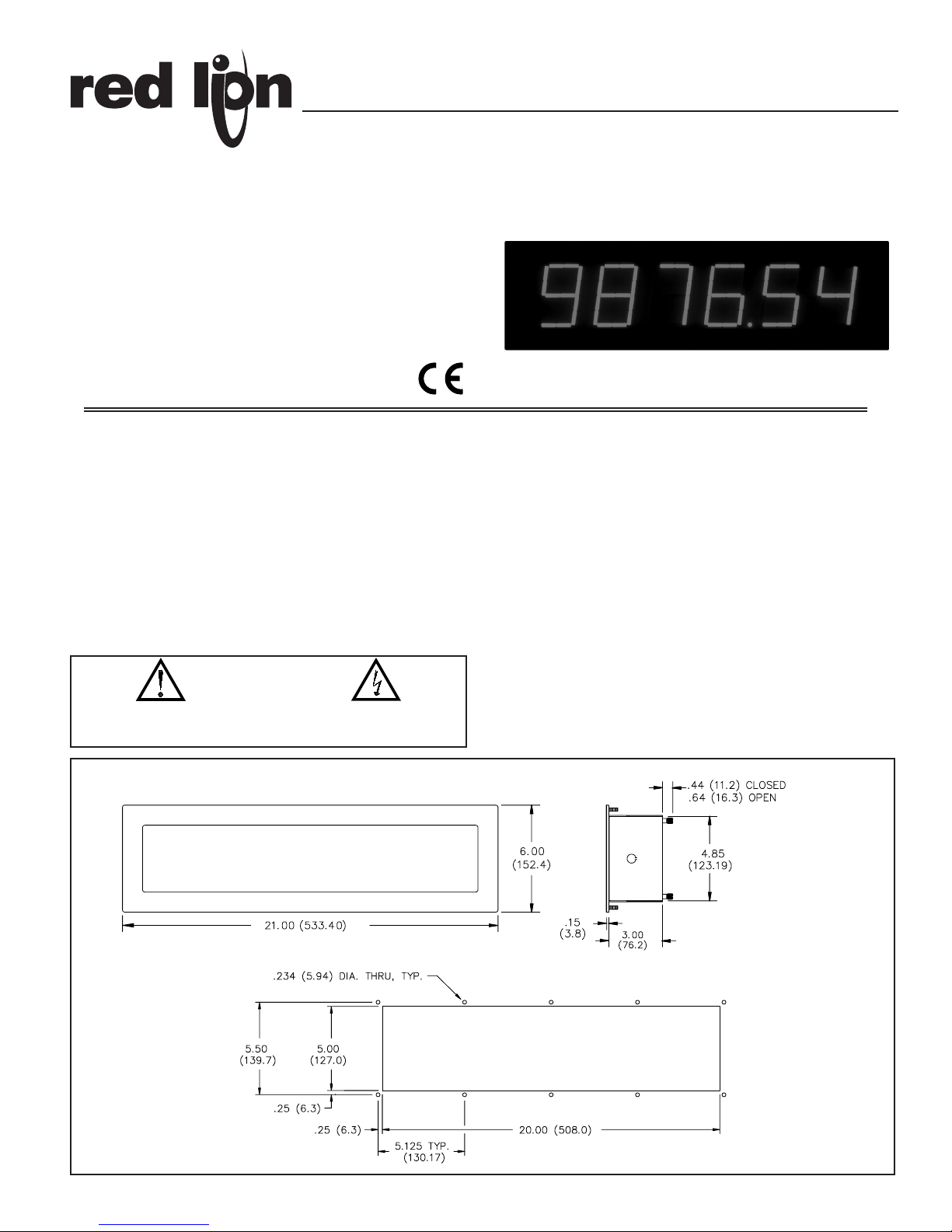
The LDD has a sealed front panel which meets NEMA 4/IP65 requirements
for wash-down and dusty environments when properly installed. The 3.32"
(84.4 mm) digits are readable to 130 feet (40 M).
SAFETY SUMMARY
All safety related regulations, local codes and instructions that appear in the
manual or on equipment must be observed to ensure personal safety and to
prevent damage to either the instrument or equipment connected to it. If
equipment is used in a manner not specified by the manufacturer, the protection
provided by the equipment may be impaired.
SPECIFICATIONS
1. DISPLAY: 3.32" (84.4 mm) High, Red or Green LED display.
2. POWER REQUIREMENTS: Switch selectable 115/230 VAC (±10%),
50/60 Hz, 17 VA 4-digit, 21 VA 6-digit (including module).
3. CONSTRUCTION: Steel construction textured with polyurethane paint for
scratch and corrosion resistance protection. Front panel meets NEMA 4/IP65
requirements for indoor use when properly installed. Installation Category II,
Pollution Degree 2. (Panel gasket included with unit.)
4. ENVIRONMENTAL CONDITIONS:
Operating Temperature: SEE MODULE LITERATURE
Storage Temperature: -40 to 70°C
Operating and Storage Humidity: 85% max. relative (non-condensing)
over operating range
Altitude: Up to 2000 meters
MODEL LDD - LARGE DIGIT DISPLAY
DIMENSIONS In inches [mm]
PANEL CUT-OUT
Bulletin No. LDD-N
Drawing No. LP0205
Released 1/06
Tel +1 (717) 767-6511
Fax +1 (717) 764-0839
www.redlion.net
CAUTION: Risk of Danger.
Read complete instructions prior to
installation and operation of the unit.
CAUTION: Risk of electric shock.
Page 2
2
SPECIFICATIONS (Cont’d)
5. CERTIFICATIONS AND COMPLIANCES:
SAFETY
IEC 61010-1, EN 61010-1: Safety requirements for electrical equipment
for measurement, control, and laboratory use, Part 1.
IP65 Enclosure rating (Face only), IEC 529
Type 4 Enclosure rating (Face only), UL50
EMC EMISSIONS: Meets EN 50081-2: Industrial Environment.
EMC IMMUNITY: Meets EN 50082-2: Industrial Environment.
Refer to individual personality module specifications for aditional
information.
6. MOUNTING REQUIREMENTS:
Max. panel thickness is 0.375" (9.5 mm).
Min. panel thickness for NEMA 4/IP65 sealing is 0.125" (3.2 mm).
7. WEIGHT: 8 lbs (3.6 kg) (less module).
Warning: Disconnect all power before installing or removing module.
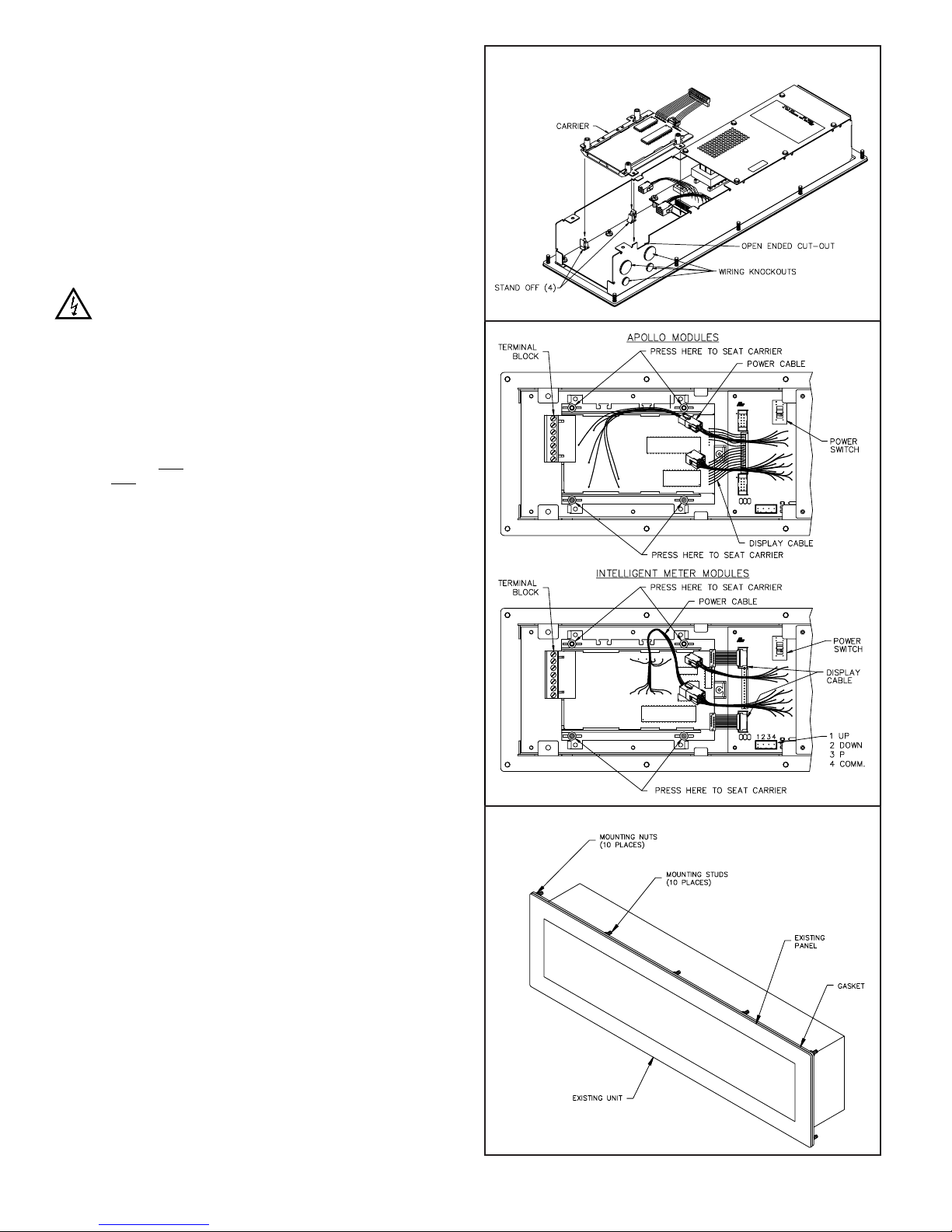
SET-UP
To place the personality module into the LDD, first remove the rear cover
by unscrewing the two captive fasteners. Then, before installing the module
into the LDD, configure the module for the specific application by SETTING
ALL APPLICABLE DIP SWITCHES AND JUMPERS AT THIS TIME (see
accompanying module data sheet). Place the module on the plastic standoffs
(see figure 1). Push on the four posts as shown in figure 2 until the carrier snaps
into place.
Note: Power should NOT be applied until the terminal block is plugged into the
module AND
the module is properly installed into the Large Digit Display.
Select the proper voltage by setting the switch to either 115 or 230 volts.
Connect the display and power cables on the module to the appropriate
connectors on the power supply board (see figure 2).
To program the Intelligent Meter, three normally open momentary
pushbuttons are connected to “P”, “UP”, “DOWN”, and common of the LDD
(not included with the Intelligent Meter). The Model PGM is a small plastic
case with three normally open momentary pushbuttons and 10 feet (3 M) of
shielded cable, and is well suited for programming the Intelligent Meter
module. Although, any normally open, momentary pushbutton switches can be
used. (SEE APPROPRIATE MODULE LITERATURE FOR SET-UP AND
OTHER CONNECTIONS.)
To remove module from the LDD, disconnect the display and power cables,
then remove the carrier from the standoffs by disengaging the tabs and
simultaneously lifting the carrier. Repeat this until the module has cleared all 4
standoffs.
INSTALLATION ENVIRONMENT
The unit should be installed in a location that does not exceed the maximum
operating temperature and provides good air circulation. Placing the unit near
devices that generate excessive heat should be avoided.
The LDD may be cleaned using alcohol compounds such as Isopropanol or
methanol. Also, liquid glass cleaners may be used if they do NOT contain
ammonia.
NOTE: MINIMAL EXPOSURE OF KETONE SOLVENTS TO THE LDD IS
GOING TO CAUSE A WHITENING OF THE DISPLAY OVERLAY.
Continuous exposure to direct sunlight may accelerate the aging process of
the bezel.
The LDD is intended to be mounted into an enclosed panel with a gasket to
provide a water-tight seal. A gasket and ten 10 to 32 kep nuts are provided for
easy installation. The recommended minimum panel thickness for NEMA
4/IP65 applications is 0.125" (3.2 mm). Thinner panels may be used but may
distort and not provide a water-tight seal.
For ease of installation, the cardboard template (supplied with the LDD) may
be used to mark the holes and cut-out locations on the panel. After the panel
cut-out has been completed and deburred, insert the unit with the panel gasket,
into the panel as depicted in the drawing (see figure 3). Install the ten kep nuts
and tighten evenly for uniform gasket compression.
By using additional hardware, the LDD can be surface-wall mounted,
suspended, or bottom mounted. To surface-wall mount the unit, two sets of
MB6 brackets are required. To suspend or bottom mount the unit, one set of
MB6 brackets is required.
FIGURE 1 (shown with cover removed)
FIGURE 2
FIGURE 3
Page 3

3
MODEL NO. DESCRIPTION PART NUMBER
PBLCK
Apollo Real Time Clock Module for use with
PBLCK000
the 6-digit Large Digit Display
(1)
Apollo 4-digit Process Time Module for use
PBLPT400
PBLPT
with the 4-digit Large Digit Display
Apollo 5-digit Process Time Module for use
PBLPT500
with the 6-digit Large Digit Display
(2)
PBLR
Apollo Time Base Rate Module for use
PBLR0600
with the 4 or 6-digit Large Digit Display
(3)
PBLRI
Apollo Time Interval Rate Module for use
PBLRI600
with the 4 or 6-digit Large Digit Display
(4)
PBLT
Apollo 6-digit Totalizer Module for use
PBLT0600
with the 4 or 6-digit Large Digit Display
(5)
(1) See APLCK Bulletin for operating specifications.
(2) See APLPT Bulletin for operating specifications.
(3) See APLR Bulletin for operating specifications.
(4) See APLRI Bulletin for operating specifications.
(5) See APLT Bulletin for operating specifications.
1. TOTALIZER
2. LINEARIZER
4-20 mA
MODEL NO. DESCRIPTION
+18 VDC 3. PEAK/VALLEY DUAL SERIAL
ANALOG PART NUMBER
EXCITATION 4. TARE ALARM OUTPUT
OUTPUT
5. E2-CON
6. EFFICIENCY
Intelligent Meter Modules NO NO NO NO NO PBD10000
For Decade Voltage Inputs* YES NO NO NO NO PBD10100
PBD1 YES NO YES NO NO PBD10102
(See IMD1 Bulletin for operating YES 1, 2, 3, 4, 5 NO NO NO PBD13100
Specifications.) YES 1, 2, 3, 4, 5 YES YES YES PBD13107
Intelligent Meter Modules NO NO NO NO NO PBD20000
For Decade Current Input* YES NO NO NO NO PBD20100
PBD2 YES NO YES NO NO PBD20102
(See IMD2 Bulletin for operating YES 1, 2, 3, 4, 5 NO NO NO PBD23100
Specifications.) YES 1, 2, 3, 4, 5 YES YES YES PBD23107
Intelligent Serial Slave Display Module* 20 mA SRC 3, 5 NO YES NO PBA04101
PBA (See IMA Bulletin for operating 20 mA SRC 3, 5 YES YES NO PBA04104
Specifications.) 20 mA SRC 3, 5 YES YES YES PBA04107
+12 VDC 1, 2, 3, 5, 6 NO NO NO PBI04100
Intelligent Digital Rate Meter* +12 VDC 1, 2, 3, 5, 6 NO YES NO PBI04101
PBI (See IMI Bulletin for operating +12 VDC 1, 2, 3, 5, 6 YES NO NO PBI04102
Specifications.) +12 VDC 1, 2, 3, 5, 6 NO NO YES PBI04103
+12 VDC 1, 2, 3, 5, 6 YES YES YES PBI04107
PGM Programming Box PGM00000
* Note: All the above Intelligent Meter modules require a 6-digit Large Digit Display, Model LDD00600 or LDD0G600.
ORDERING INFORMATION FOR APOLLO INTELLIGENT METER MODULES
ORDERING INFORMATION
FOR APOLLO PERSONALITY MODULES
ORDERING INFORMATION FOR LARGE DIGIT DISPLAY
MODEL NO. DESCRIPTION PART NUMBER
4-digit, Red Large Digit Display LDD00400
LDD
4-digit, Green Large Digit Display LDD0G400
6-digit, Red Large Digit Display LDD00600
6-digit, Green Large Digit Display LDD0G600
MB6 Mounting Brackets MB600000
ENC7 LDD NEMA 4/IP65 Enclosure ENC70000
SHR Shroud For LDD SHR10000
ORDERING INFORMATION
FOR APOLLO BCD SLAVE MODULE
MODEL NO. DESCRIPTION PART NUMBER
Apollo BCD Slave Display Module for use
PBLSP
with 4 or 6-digit Large Digit Display
PBLSP600
(See APLSP Bulletin for operating
specifications.)
PERSONALITY MODULES
The following Apollo and IM capabilities are available as modules for the
Large Digit Display (LDD). These modules are ordered separately from the
LDD (see ordering information), and can quickly be installed by the user (see
“Set-up” for further details).
Application
Model Digit Display
Number Required
Counting (Totalization) PBLT0600 4/6-digit
Tachometer/Rate (Time Base) PBLR0600 4/6-digit
Tachometer/Rate (Time Interval) PBLRI600 4/6-digit
Process Time (Decimal Point) PBLPT400 4-digit
Process Time (Chronometer) PBLPT500 6-digit
Real Time Clock/Elapsed Time PBLCK000 6-digit
Intelligent Decade Voltmeter (IMD1) PBD1xxxx 6-digit
Intelligent Decade Current Meter (IMD2) PBD2xxxx 6-digit
Intelligent Rate Meter (IMI) PBIxxxxx 6-digit
Intelligent Slave Display (IMA) PBAxxxxx 6-digit
Apollo Slave Display (APLSP) PBLSP600 4/6-digit
TROUBLESHOOTING
For further technical assistance, contact technical support at the appropriate
company numbers listed.
Page 4

LIMITED WARRANTY
The Company warrants the products it manufactures against defects in materials and workmanship
for a period limited to two years from the date of shipment, provided the products have been stored,
handled, installed, and used under proper conditions. The Company’s liability under this limited
warranty shall extend only to the repair or replacement of a defective product, at The Company’s
option. The Company disclaims all liability for any affirmation, promise or representation with
respect to the products.
The customer agrees to hold Red Lion Controls harmless from, defend, and indemnify RLC against
damages, claims, and expenses arising out of subsequent sales of RLC products or products
containing components manufactured by RLC and based upon personal injuries, deaths, property
damage, lost profits, and other matters which Buyer, its employees, or sub-contractors are or may be
to any extent liable, including without limitation penalties imposed by the Consumer Product Safety
Act (P.L. 92-573) and liability imposed upon any person pursuant to the Magnuson-Moss Warranty
Act (P.L. 93-637), as now in effect or as amended hereafter.
No warranties expressed or implied are created with respect to The Company’s products except those
expressly contained herein. The Customer acknowledges the disclaimers and limitations contained
herein and relies on no other warranties or affirmations.
Red Lion Controls
20 Willow Springs Circle
York PA 17402
Tel +1 (717) 767-6511
Fax +1 (717) 764-0839
Red Lion Controls AP
31, Kaki Bukit Road 3,
#06-04/05 TechLink
Singapore 417818
Tel +65 6744-6613
Fax +65 6743-3360
Red Lion Controls BV
Basicweg 11b
NL - 3821 BR Amersfoort
Tel +31 (0) 334 723 225
Fax +31 (0) 334 893 793
 Loading...